patent · US20060219190A1
Hydrogen generating apparatus and components therefor
5 October 2006
Page 1 — bibliographic record
(19) United States (12) Patent Application Publication (10) Pub. No.: US 2006/0219.190 A1
Balan et al. (43) Pub. Date: Oct. 5, 2006 (54) HYDROGEN GENERATING APPARATUS (60) Provisional application No. 60/262,395, filed on Jan. AND COMPONENTS THEREFOR 19, 2001.
(75) Inventors: Gabi Balan, Dunmore (CA); Johnston Publication Classification Donald, Calgary (CA); Daniela Balan,
Calgary (CA); Mario Phillip De Souza, FO2B 43/08 (2006.01) Dunmore (CA) (52) U.S. Cl. .................................................................. 123A3 Correspondence Address: (57) ABSTRACT
BENNETT JONES
CFO MS ROSEANN CALDWELL
4500 BANKERS HALL EAST
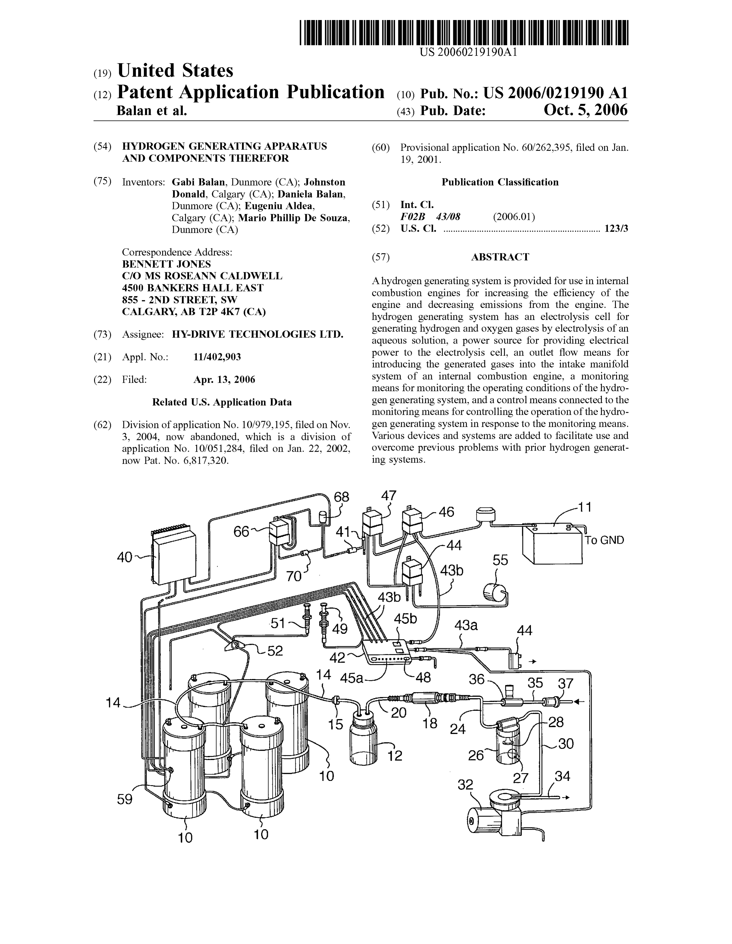
A hydrogen generating system is provided for use in internal combustion engines for increasing the efficiency of the 855 - 2ND STREET, SW engine and decreasing emissions from the engine. The CALGARY, AB T2P 4K7 (CA) hydrogen generating system has an electrolysis cell for generating hydrogen and oxygen gases by electrolysis of an (73) Assignee: HY-DRIVE TECHNOLOGIES LTD. aqueous Solution, a power source for providing electrical (21) Appl. No.: 11/402,903 power to the electrolysis cell, an outlet flow means for introducing the generated gases into the intake manifold (22) Filed: Apr. 13, 2006 system of an internal combustion engine, a monitoring means for monitoring the operating conditions of the hydro
Related U.S. Application Data gen generating system, and a control means connected to the monitoring means for controlling the operation of the hydro (62) Division of application No. 10/979, 195, filed on Nov. gen generating system in response to the monitoring means. 3, 2004, now abandoned, which is a division of Various devices and systems are added to facilitate use and application No. 10/051,284, filed on Jan. 22, 2002, overcome previous problems with prior hydrogen generat now Pat. No. 6,817,320. ing Systems.
Page 2
Drawing sheet — no readable text.
Page 3
Drawing sheet — no readable text.
Page 4
Drawing sheet — no readable text.
Page 5
Drawing sheet — no readable text.
Page 6
Patent Application Publication Oct. 5, 2006 Sheet 5 of 5 US 2006/0219.190 A1
50a . 5Ob H2 5Oc H2
POWer External RAM and ROM O6
PrOCeSSOr Of MicroController Chip OO
PROM of chip (Program area) O4
RAMOf chip (Variables)
Input/Output (I/O) ports of chip
InterfaCeS
Serial Parallel Parallel Parallel Serial Digital Digital Analog Digital Digital inputs inputs InputS Outputs Outputs FIG. 8
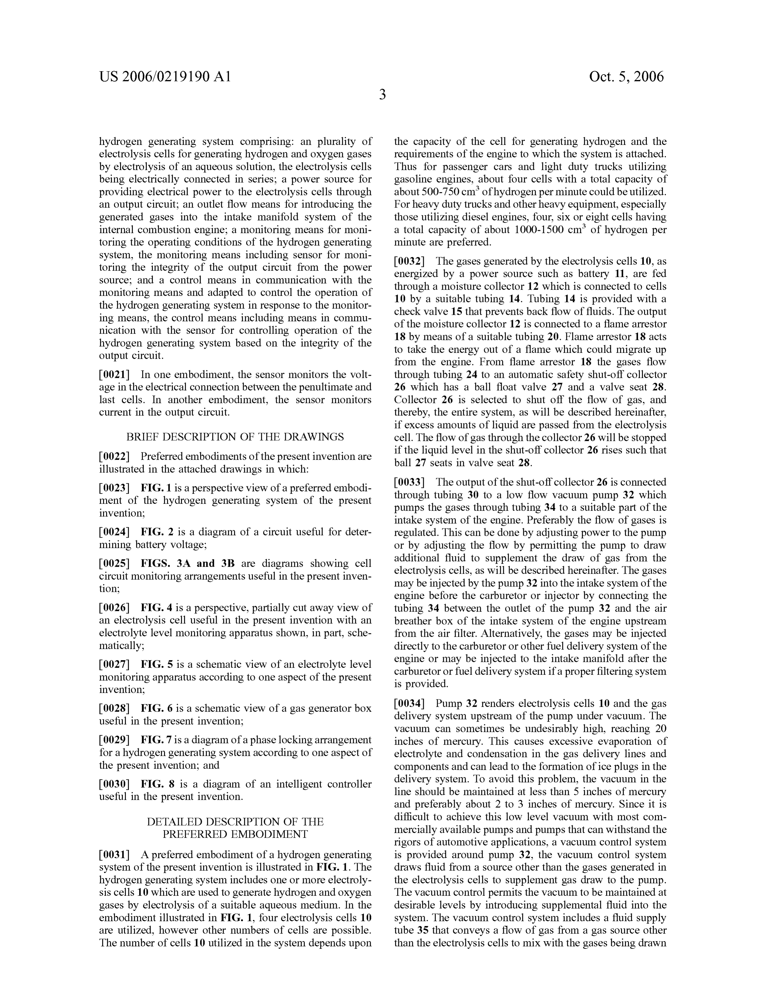
Page 7
US 2006/0219 190 A1 Oct. 5, 2006
HYDROGEN GENERATING APPARATUS AND 0007 Although much work has been conducted to COMPONENTS THEREFOR advance automotive electrolysis systems, these systems have not been generally accepted due to safety and conve
FIELD OF THE INVENTION nience concerns. A hydrogen generating system is required which overcomes at least Some of the safety and conve 0001. The present invention is directed to a hydrogen nience problems of previous systems. generating apparatus and in particular a hydrogen generating apparatus for use in motor vehicles to increase the perfor SUMMARY OF THE INVENTION mance of the engine of the motor vehicle.
0008. The present invention is directed to a hydrogen
BACKGROUND OF THE INVENTION generating system for use in internal combustion engines for increasing the efficiency of the engine and decreasing emis 0002 The use of hydrogen as a supplemental fuel in sions from the engine. The hydrogen generating system of motor vehicle engines has been proposed to increase the the present invention comprises an electrolysis cell for performance of the engine. Hydrogen and oxygen, when generating hydrogen and oxygen gases by electrolysis of an used as part of the air/fuel mixture for the operation of the aqueous Solution, a power source for providing electrical engine, have been found to increase the performance of the power to the electrolysis cell and an outlet flow means for engine by increasing the mileage and by reducing the introducing the generated gases into the intake manifold amount of emissions from the engine. The hydrogen and system of an internal combustion engine. oxygen may be generated through electrolysis of an aqueous solution with the gases given off being mixed with the fuel 0009. In accordance with one aspect of the present inven and air supplied to the engine. tion there is provided a hydrogen generating system for use in an internal combustion engine for increasing the effi 0003. The generation of small quantities of hydrogen and ciency of the engine and decreasing emissions from the oxygen using one or more electrolysis cells with the hydro engine, the hydrogen generating system comprising: an gen and oxygen generated then being combined with the electrolysis cell for generating hydrogen and oxygen gases usual air/fuel mixture to improve the efficiency of internal by electrolysis of an aqueous solution, a power Source for combustion engines has been proposed in a number of prior providing electrical power to the electrolysis cell; an outlet patents. Some systems of these prior patents utilized the flow means for introducing the generated gases into the alternator or an auxiliary generator attached to the engine to intake manifold system of an internal combustion engine; a provide the electrical power for the system. monitoring means for monitoring the operating conditions of 0004 One example of such a system is shown in U.S. Pat. the hydrogen generating system, the monitoring means No. 4.271,793. This patent describes an internal combustion including an electrolyte level monitoring device in the engine having a fuel system for feeding an air/fuel mixture electrolysis cell including a tube, a circuit disposed in the to the combustion chamber and an electrical generation tube, the circuit including a Switch positioned adjacent a system, such as an alternator. An electrolysis cell was selected level of the aqueous solution and a float selected to attached adjacent to the engine to generate hydrogen and float on the aqueous solution, the float being slidably oxygen upon the application of a Voltage between the engaged on the tube, and free to ride along the tube as driven cathode and the anode of the electrolysis cell. A gas delivery by changes in the Surface level of the aqueous solution and connects the cell to the engine fuel system for feeding the the float including means for actuating the Switch as it rides hydrogen and oxygen to the engine combustion chambers. along the tube; and a control means in communication with The electrolysis cell was placed under a predetermined the monitoring means and adapted to control the operation pressure to prevent the electrolyte from boiling off. The cell of the hydrogen generating system in response to the moni also included a cooling system and other safety features. toring means, the control means including means in com munication with the electrolyte level monitoring device and 0005) Another electrolysis cell is disclosed in U.S. Pat. adapted to indicate when the level of the aqueous solution No. 5.231,954. The electrolysis cell of this patent was used reaches the selected level as indicated by the float actuating for generating hydrogen and oxygen gases which were the switch.
added to the fuel delivery system as a supplement to the gasoline or other hydrocarbons burned therein. The cell was 0010. In one embodiment the switch is a reed switch designed to reduce the hazard of explosion by withdrawing disposed within the tube. There can be any number of the gases through a connection with the vacuum line of the switches in the circuit, preferably there are one or two positive crankcase ventilation (PCV) system of the engine Switches. A magnet can be disposed in the float to act as the and by utilizing a slip-fitted top cap for the electrolysis cell. means for actuating the Switch. In one embodiment, the 0006 A further example of an electrolysis cell for use in control means lights an indicator light close to the cell to indicate when the liquid level rises to an upper acceptable connection with an internal combustion engine, for gener level. In a preferred embodiment, the circuit enters the cell ating hydrogen and oxygen gases is shown in U.S. Pat. No. though an opening in the cell which is positioned above the 5,458,095. This system utilized an electric pump to draw the normal upper level of the fluid. hydrogen and oxygen gases out of the cell, where the outlet side of the pump was connected to the air intake manifold 0011. In accordance with another aspect of the present using a hose having a terminating insert. The insert was invention, there is provided a hydrogen generating system formed from copper tubing bent at an appropriate angle to for use in an internal combustion engine for increasing the insure that the hydrogen and oxygen gas outlet from the efficiency of the engine and decreasing emissions from the pump was in the same direction as the downstream airflow engine, the hydrogen generating system comprising: an in the air intake manifold. electrolysis cell for generating hydrogen and oxygen gases
Page 8
US 2006/0219 190 A1 Oct. 5, 2006
by electrolysis of an aqueous Solution contained within the sions from the engine, the hydrogen generating system cell, the electrolysis cell having an outer Surface; a power comprising: at least one electrolysis cell for generating source for providing electrical power to the electrolysis cell; hydrogen and oxygen gases by electrolysis of an aqueous an outlet flow means for introducing the generated gases into Solution; a power source for providing electrical power to the intake manifold system of an internal combustion the electrolysis cell; an outlet flow means for introducing the engine; a monitoring means for monitoring the operating generated gases into the intake manifold system of an conditions of the hydrogen generating system, the monitor internal combustion engine, the outlet flow means including ing means including an electrolyte level monitoring device a vacuum pump for drawing the generated gases under including a tank circuit having an inductor and a capacitor vacuum toward the internal combustion engine, the vacuum connected in parallel, the inductor being an electrical wire pump having an inlet tubing and an outlet tubing and a wrapped at least one turn about the electrolysis cell adjacent vacuum control arrangement for conveying Supplemental a selected level of the aqueous solution within the electroly gas from gas source and introducing the Substantial gases to sis cell, and interface circuitry for exciting the tank circuit the generated gases in the inlet tubing to reduce the vacuum Such that a sine wave is generated and observing evidence of generated by the vacuum pump; a monitoring means for energy loss in the circuit; and a control means in commu monitoring the operating conditions of the hydrogen gener nication with the monitoring means and adapted to control ating system; and a control means in communication with the operation of the hydrogen generating system in response the monitoring means and adapted to control the operation to the monitoring means, the control means including means of the hydrogen generating system in response to the moni in communication with the electrolyte level monitoring toring means.
device and adapted to indicate when the level of the aqueous 0016. The gas source can be atmospheric air, gases from solution reaches the selected level as indicated by the energy the exhaust gas manifold of the vehicle or gases from the air loss in the circuit.
intake of the vehicle, preferably downstream of the mass air 0012 Preferably, the circuit is disposed about the outer flow sensor. In one embodiment, the Supplemental gas is Surface of the electrolysis cell so that no opening through the heated over the temperature of ambient air. Alternately or in cell housing need be made. This avoids creating an opening addition, the supplemental air can be filtered and/or dried. Susceptible to leakage. In one embodiment, there is an upper 0017. In one embodiment, the vacuum control arrange tank circuit and a lower tank circuit, indicating an upper ment includes a valve for controlling the flow of supple electrolyte level and a lower electrolyte level respectively. mental gas into the inlet tubing. The Supplemental air is The control means can be adapted to indicate level of preferably introduced to the inlet tubing between a flame electrolyte solution reaches the selected level by shutting arrestor and the vacuum pump.
down operation of the system, by Sounding an alarm, by sending a message to a user display or by illumination of a 0018. In another aspect of the present invention, there is light. provided a hydrogen generating system for use in an internal combustion engine of a vehicle for increasing the efficiency 0013 In accordance with another aspect of the present of the engine and decreasing emissions from the engine, the invention, there is provided a hydrogen generating system hydrogen generating system comprising: a plurality of mod for use in an internal combustion engine of a vehicle for ules, each module containing an electrolysis cell for gener increasing the efficiency of the engine and decreasing emis ating hydrogen and oxygen gases by electrolysis of an sions from the engine, the hydrogen generating system aqueous Solution; a power regulator for providing regulated comprising: an electrolysis cell for generating hydrogen and electrical power to the electrolysis cell, the power regulator oxygen gases by electrolysis of an aqueous solution; a power generating an AC component; an outlet flow means for source for providing electrical power to the electrolysis cell introducing the generated gases from the cells into the intake as Supplied by a battery power Supply; an outlet flow means manifold system of the internal combustion engine; a moni for introducing the generated gases into the intake manifold toring means for monitoring the operating conditions of the system of the internal combustion engine; a monitoring hydrogen generating system; a control means in communi means for monitoring the operating conditions of the hydro cation with the monitoring means and adapted to control the gen generating System, the monitoring means including a operation of the hydrogen generating system in response to sensor for monitoring battery Voltage; and a control means the monitoring means; and wherein the AC component of in communication with the monitoring means and adapted to the power regulators are phase locked with a selected control the operation of the hydrogen generating system in module acting as the master module and a selected others of response to the monitoring means, the control means includ the modules acting as slave modules. ing means for comparing the battery Voltage to a Voltage indicative of proper alternator operation and controlling 0019. In one embodiment, each module contains phase operation of the hydrogen generating system when the locking circuitry, the phase locking circuitry of the master battery Voltage is not indicative of proper alternator opera module generating a chopping frequency and inputting the tion. chopping frequency to the slave modules. The system can further comprise a controller selected to prevent the opera 0014. In one embodiment, the control means is further tion of any slave modules not phase locked with the master adapted to indicate that the battery voltage is not indicative module. The controller can be a subroutine in the control of proper alternator operation. CaS.
0015. In accordance with another aspect of the present 0020. In another aspect of the present invention there is invention, there is provided a hydrogen generating system provided a hydrogen generating system for use in an internal for use in an internal combustion engine of a vehicle for combustion engine of a vehicle for increasing the efficiency increasing the efficiency of the engine and decreasing emis of the engine and decreasing emissions from the engine, the
Page 9
US 2006/0219 190 A1 Oct. 5, 2006
hydrogen generating system comprising: an plurality of the capacity of the cell for generating hydrogen and the electrolysis cells for generating hydrogen and oxygen gases requirements of the engine to which the system is attached. by electrolysis of an aqueous solution, the electrolysis cells Thus for passenger cars and light duty trucks utilizing being electrically connected in series; a power source for gasoline engines, about four cells with a total capacity of providing electrical power to the electrolysis cells through about 500-750 cm of hydrogen per minute could be utilized. an output circuit; an outlet flow means for introducing the For heavy duty trucks and other heavy equipment, especially generated gases into the intake manifold system of the those utilizing diesel engines, four, six or eight cells having internal combustion engine; a monitoring means for moni a total capacity of about 1000-1500 cm of hydrogen per toring the operating conditions of the hydrogen generating minute are preferred.
system, the monitoring means including sensor for moni 0032. The gases generated by the electrolysis cells 10, as toring the integrity of the output circuit from the power energized by a power source Such as battery 11, are fed Source; and a control means in communication with the through a moisture collector 12 which is connected to cells monitoring means and adapted to control the operation of 10 by a suitable tubing 14. Tubing 14 is provided with a the hydrogen generating system in response to the monitor check valve 15 that prevents back flow of fluids. The output ing means, the control means including means in commu of the moisture collector 12 is connected to a flame arrestor nication with the sensor for controlling operation of the 18 by means of a suitable tubing 20. Flame arrestor 18 acts hydrogen generating system based on the integrity of the to take the energy out of a flame which could migrate up output circuit. from the engine. From flame arrestor 18 the gases flow 0021. In one embodiment, the sensor monitors the volt through tubing 24 to an automatic safety shut-off collector age in the electrical connection between the penultimate and 26 which has a ball float valve 27 and a valve seat 28. last cells. In another embodiment, the sensor monitors Collector 26 is selected to shut off the flow of gas, and current in the output circuit. thereby, the entire system, as will be described hereinafter, if excess amounts of liquid are passed from the electrolysis
BRIEF DESCRIPTION OF THE DRAWINGS cell. The flow of gas through the collector 26 will be stopped 0022 Preferred embodiments of the present invention are if the liquid level in the shut-off collector 26 rises such that ball 27 seats in valve seat 28.
illustrated in the attached drawings in which:
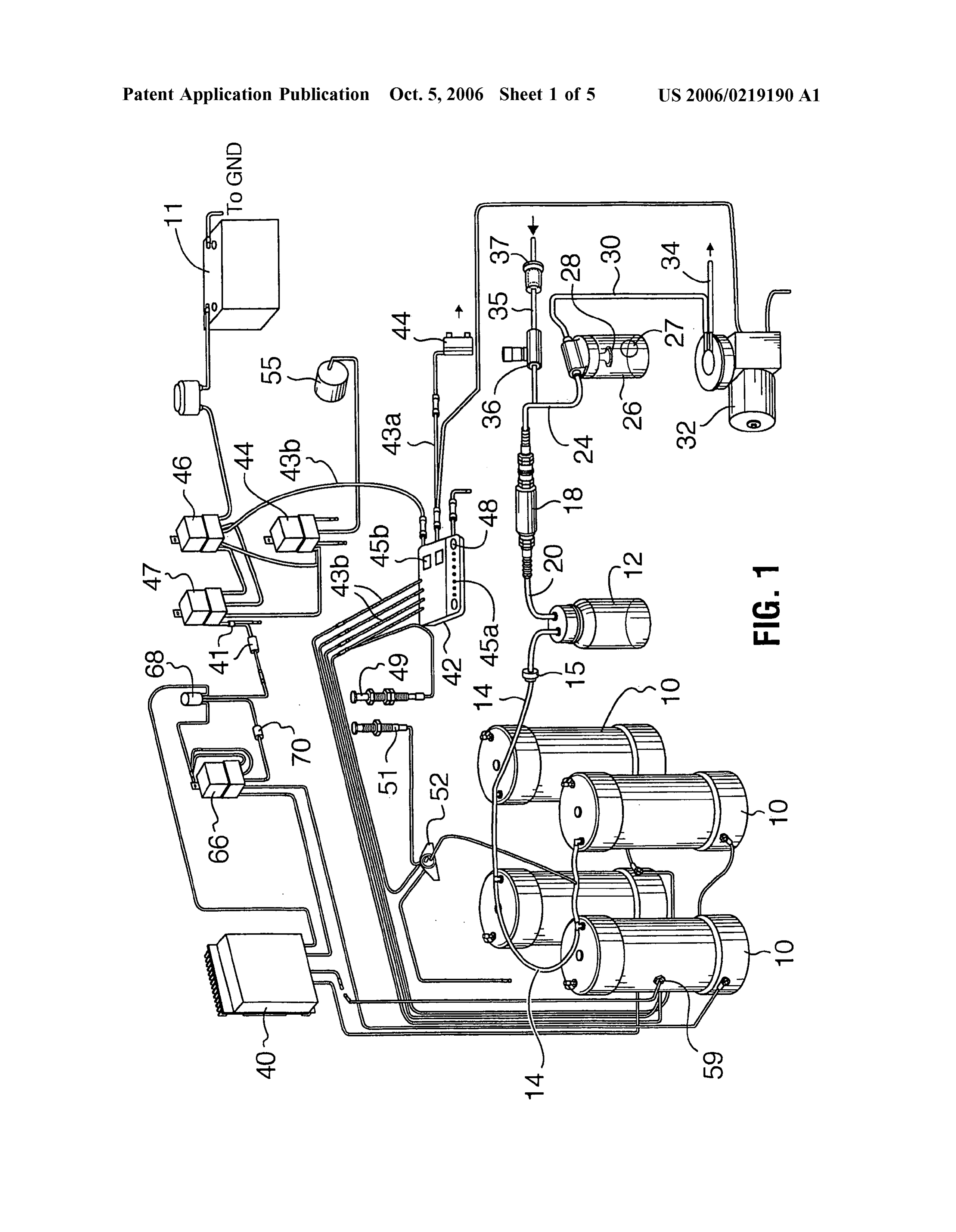
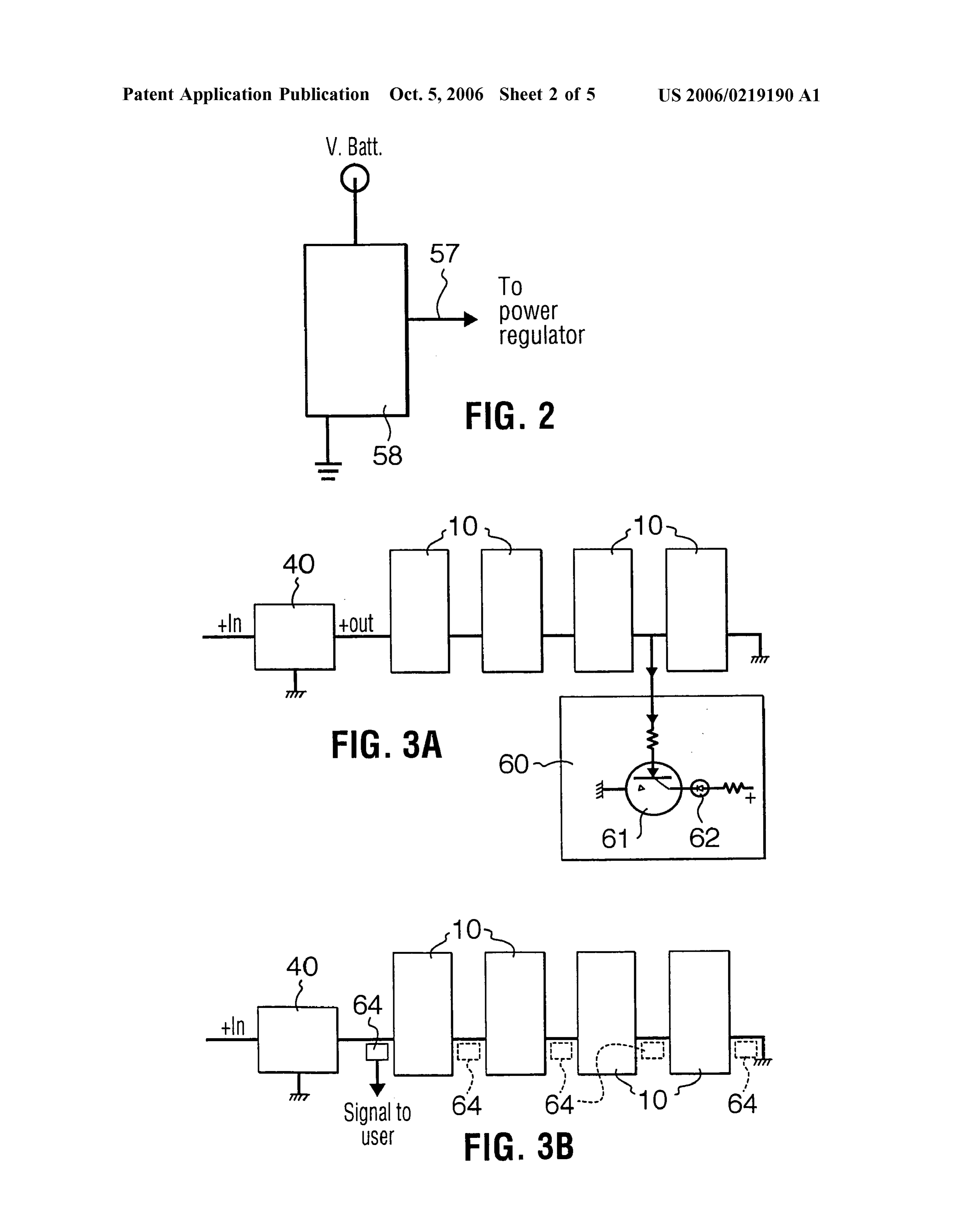
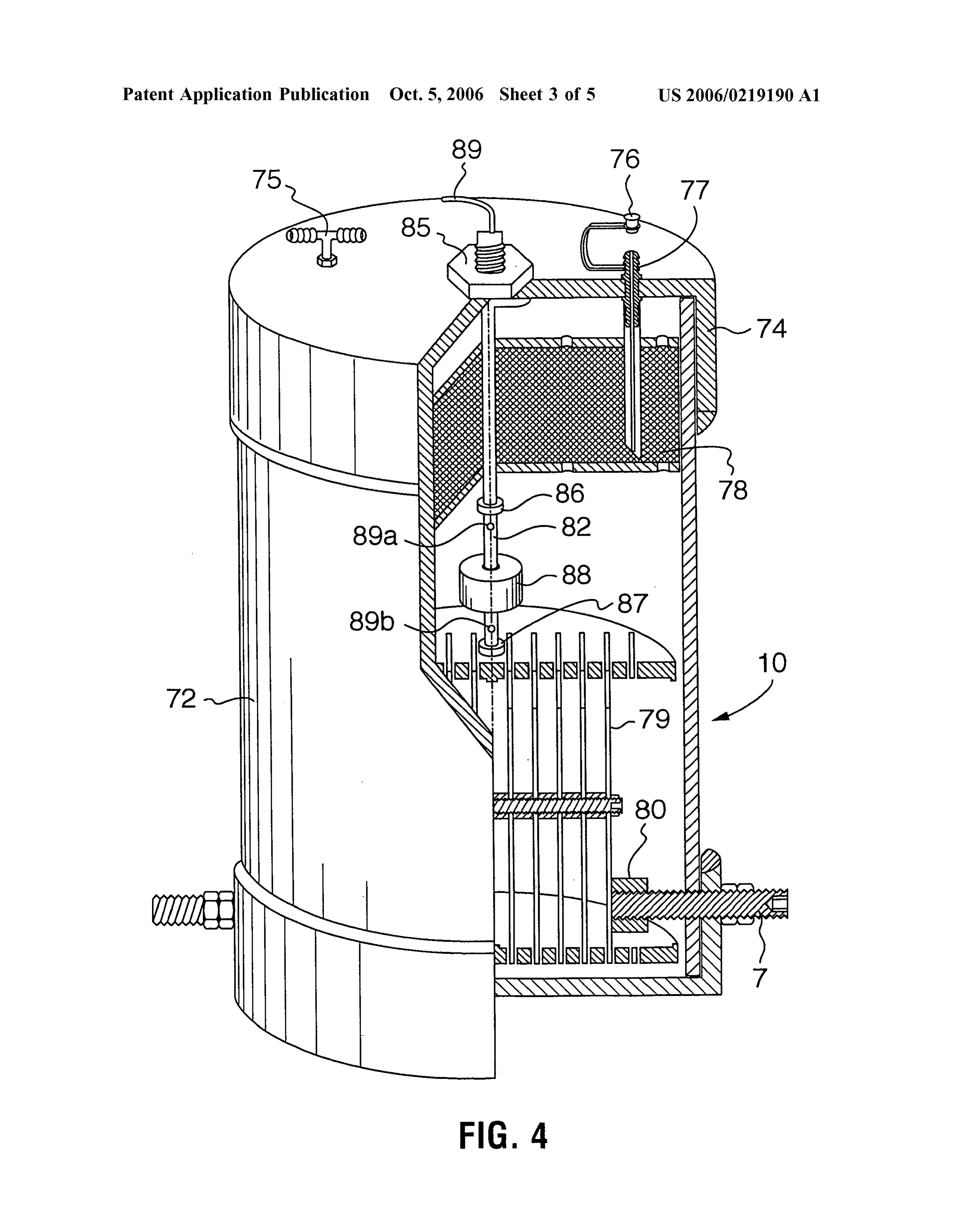
0023 FIG. 1 is a perspective view of a preferred embodi 0033. The output of the shut-off collector 26 is connected ment of the hydrogen generating system of the present through tubing 30 to a low flow vacuum pump 32 which invention; pumps the gases through tubing 34 to a Suitable part of the intake system of the engine. Preferably the flow of gases is 0024 FIG. 2 is a diagram of a circuit useful for deter regulated. This can be done by adjusting power to the pump mining battery Voltage; or by adjusting the flow by permitting the pump to draw 0025 FIGS. 3A and 3B are diagrams showing cell additional fluid to supplement the draw of gas from the circuit monitoring arrangements useful in the present inven electrolysis cells, as will be described hereinafter. The gases tion; may be injected by the pump 32 into the intake system of the engine before the carburetor or injector by connecting the 0026 FIG. 4 is a perspective, partially cut away view of tubing 34 between the outlet of the pump 32 and the air an electrolysis cell useful in the present invention with an breather box of the intake system of the engine upstream electrolyte level monitoring apparatus shown, in part, sche from the air filter. Alternatively, the gases may be injected matically; directly to the carburetor or other fuel delivery system of the 0027 FIG. 5 is a schematic view of an electrolyte level engine or may be injected to the intake manifold after the monitoring apparatus according to one aspect of the present carburetor or fuel delivery system if a proper filtering system invention; is provided.
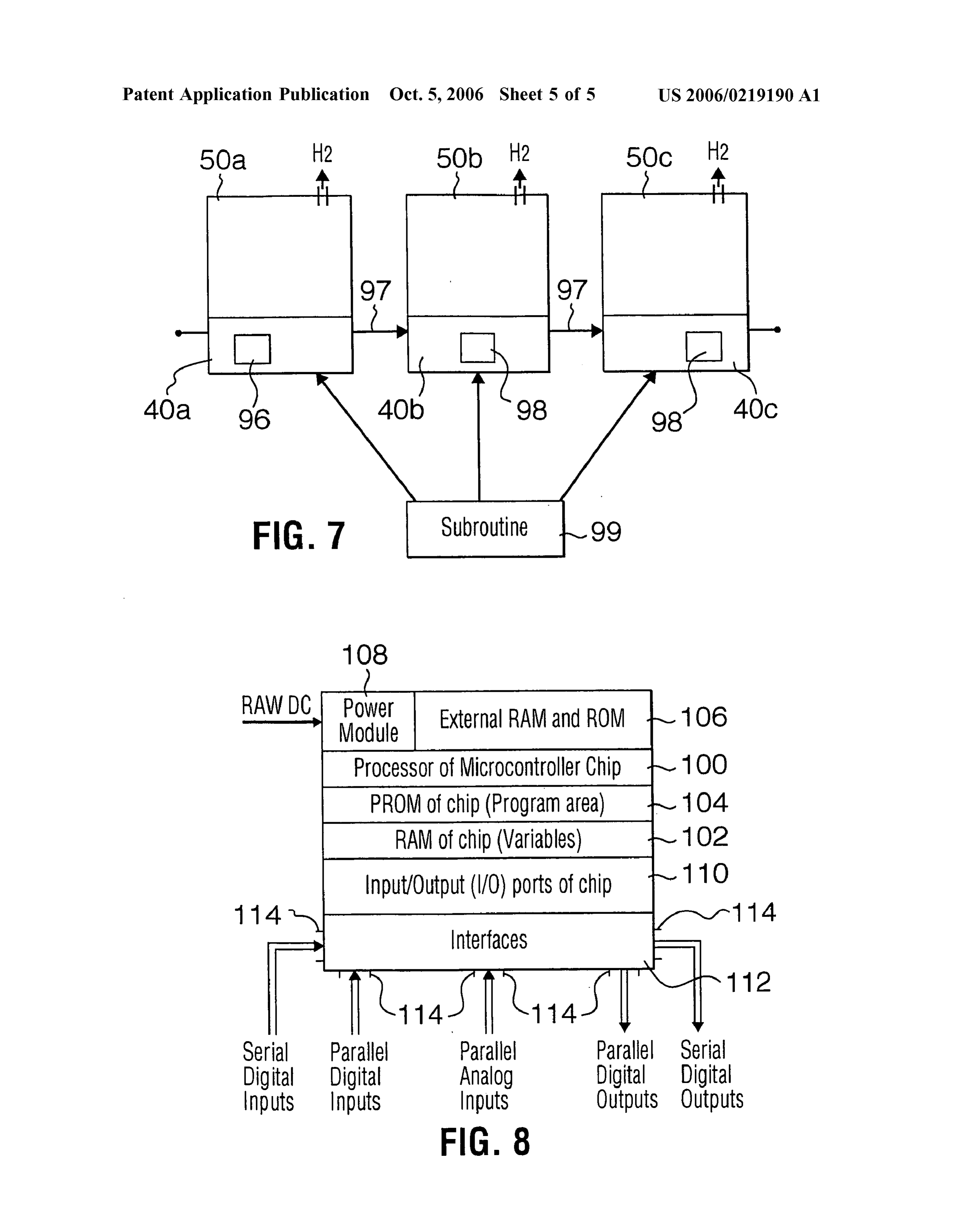
0028 FIG. 6 is a schematic view of a gas generator box 0034 Pump 32 renders electrolysis cells 10 and the gas useful in the present invention; delivery system upstream of the pump under vacuum. The vacuum can sometimes be undesirably high, reaching 20 0029 FIG. 7 is a diagram of a phase locking arrangement inches of mercury. This causes excessive evaporation of for a hydrogen generating system according to one aspect of electrolyte and condensation in the gas delivery lines and the present invention; and components and can lead to the formation of ice plugs in the 0030 FIG. 8 is a diagram of an intelligent controller delivery system. To avoid this problem, the vacuum in the useful in the present invention. line should be maintained at less than 5 inches of mercury and preferably about 2 to 3 inches of mercury. Since it is
DETAILED DESCRIPTION OF THE difficult to achieve this low level vacuum with most com PREFERRED EMBODIMENT mercially available pumps and pumps that can withstand the rigors of automotive applications, a vacuum control system 0.031) A preferred embodiment of a hydrogen generating is provided around pump 32, the vacuum control system system of the present invention is illustrated in FIG. 1. The draws fluid from a source other than the gases generated in hydrogen generating system includes one or more electroly the electrolysis cells to Supplement gas draw to the pump. sis cells 10 which are used to generate hydrogen and oxygen The vacuum control permits the vacuum to be maintained at gases by electrolysis of a Suitable aqueous medium. In the desirable levels by introducing supplemental fluid into the embodiment illustrated in FIG. 1, four electrolysis cells 10 system. The vacuum control system includes a fluid Supply are utilized, however other numbers of cells are possible. tube 35 that conveys a flow of gas from a gas source other The number of cells 10 utilized in the system depends upon than the electrolysis cells to mix with the gases being drawn
Page 10
US 2006/0219 190 A1 Oct. 5, 2006
from the electrolysis cells 10 by the pump. While the gas line 43a to the ignition of the motor vehicle with a suitably Source can be, for example, the gas in tubing 34 or atmo sized fuse 44 such as a 5 amp fuse and through lines 43b to spheric air, preferably the gas source is filtered, heated other components of the hydrogen generating system. and/or dried Such as gases from the exhaust gas manifold, 0041. The hydrogen generating system preferably also exhaust gas recirculation systems of the vehicle in which the provides for visual feedback to the operator of the motor hydrogen generating system is installed or air from the air vehicle. The dash module 42 can be provided with one or intake which has already been metered by the mass air flow more LED displays 45a, for example one LED display sensor. Using air from the air intake permits the monitoring indicating when the power is turned on to the system, and a of total air mixing with fuel. second LED display to indicate trouble with the system. 0035 Tube 35 opens into the gas delivery system Preferably, the system is provided with a display module that between flame arrestor 18 and pump 32. A particulate filter includes an alphanumeric display 45b, which can display 37 is preferably used in the tubing. For safety, tube 35 should system messages provided by a controller Such as, for not be connected upstream of the flame arrestor, as will be example, "System OK', etc.
appreciated. To control the flow of air through tube and into 0042. The hydrogen generating system of the present the gas delivery system, a needle valve 36 is mounted in tube invention includes suitable control and monitoring means 35. Needle valve 36 provides precise control over the flow for safe and effective operation. In a preferred embodiment, through tube 35 and, thereby, control over and reduction of the control means maximizes system efficiency under vari the vacuum in the gas delivery system. Introduction of ous conditions of operation of the engine. Supplemental gases can reduce relative humidity in the gas delivery system and reduces electrolyte evaporation by 0043. This control can be provided in various ways such reducing vacuum in the cells. The use of a heated, dried gas as by decentralized or centralized controllers using discrete Source also avoids the formation of ice in the gas delivery or intelligent logic. Of course the use of centralized, intel system. ligent control, such as that described hereinafter in reference 0036) Needle valve 36 can be controlled manually or to FIG. 8, is preferred as it is less expensive, more easily automatically by a control system working with a vacuum adapted to changes in the system, etc. In one embodiment, sensor. The needle valve can be replaced by other flow the monitoring means are in communication with a main control means. For example, in another embodiment, needle microprocessor controller that uses intelligence, established in Software, for control of the hydrogen generating system.
valve 36 is replaced by a check valve. The check valve is The central controller could be located anywhere in the selected to open, allowing a controlled amount of Supple vehicle Such as, for example, with the power regulator or in mental gas to flow into the electrolysis gas delivery system, the dash module. Other specialized microcontrollers could when the gases in the delivery system reach a preselected be added to communicate with the main microprocessor, if upper limit of vacuum such as 5 inches of mercury. desired.
0037. The hydrogen generating system includes a power 0044) In the embodiment illustrated in FIG. 1, control is regulator 40 for conditioning power to the electrolysis cells. decentralized and includes discrete components. While Preferably power regulator 40 is a controllable, logic-ready Some control is at the sensor level, dash module 42 houses device, having as its main component a DC-DC power most of the control logic. Various monitoring means and converter working in current limit with a logic interface switches, as will be described hereinbelow, communicate capable of output proportional to a binary input. Since the with the dash module control logic for system operation. amount of power Supplied to the electrolysis cells controls the electrolysis reaction, power regulator 40 is preferably 0045. A first relay or solenoid 46 is operated by dash capable of varying the current output to a profile Supplied by module 42 to cut power to the power regulator 40 in a controller, which will result in optimum hydrogen and response to a signal from one or more of the various oxygen quantities being produced and then delivered to the monitoring means or Switches. Another relay 47 is con engine. This allows the output of the system to be adjusted trolled in the same way as relay 46 to work in redundancy to optimum profiles, according to the demand. therewith. In a preferred embodiment the relays 46 and/or 47 are incorporated into power regulator 40.
0038. The electrical lines of the hydrogen generating system can sometimes generate electromagnetic interference 0046) When relays 46 and/or 47 shut down the operation (EMI). The EMI can interfere with audio signals such as of the electrolysis cells, it is preferred that the residual those in the FM and CB range. To reduce interference, the energy stored in the cells 10 be removed. This is preferably magnetic field can be reflected back to the emitting compo accomplished by a relay 66 with a capacitor 68 and resistor nents by use of a ferrite bead and capacitor combination 41 70. When power is cut to the electrolysis cells, relay 66 is or RF shielded coatings around the wires. activated and connects the cells to ground to bleed off any 0039. A bus arrangement can be used in the electrical residual energy stored in the cells. system, as this provides flexibility. 0047 The controller in dash module 42 also communi cates with pump 32 and can shut down its operation in 0040. A dash module 42 is provided to allow the user to response to signals from the various monitoring means and interact with the hydrogen generating system. Dash module Switches.
42 is mounted on the motor vehicle in a location easily accessible by the operator of the motor vehicle. The dash 0048 For safety and for system protection, one or more module allows the operator of the motor vehicle to control safety shutoff Switches and safety monitoring features are and monitor the hydrogen generating system as required or provided for manual or automatic shutdown and/or adjust desired. The dash module 42 is connected via an electrical ment of electrolysis in the system. Not all of the switches/
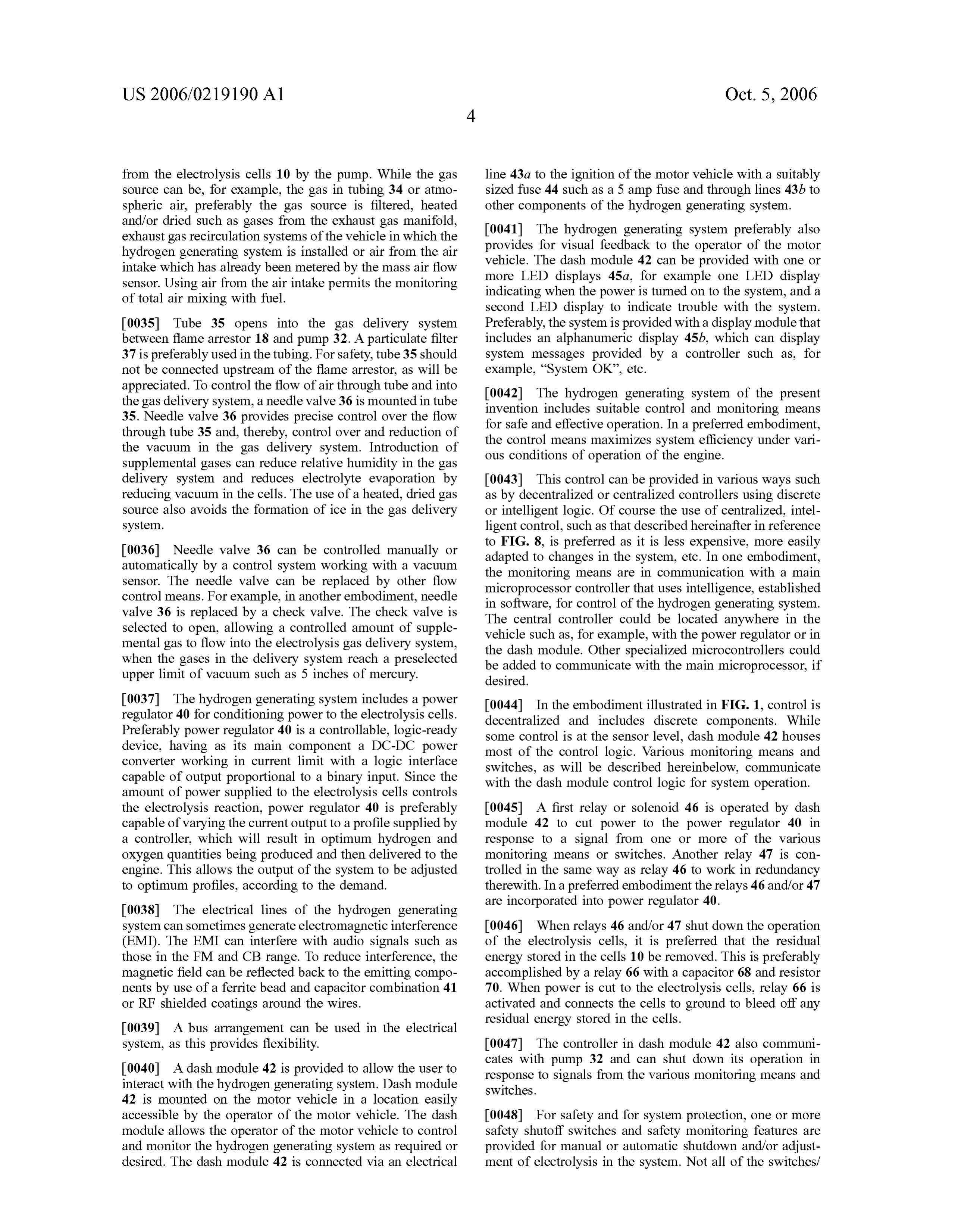
Page 11
US 2006/0219 190 A1 Oct. 5, 2006
sensors need be in any one system and, as will be appreci more than one sensor to accommodate more than one type ated, some of the monitoring means and Switches are best of installation. With the exception of the collection of signals suited to control by an intelligent controller rather than by of the vehicle computer, all of these sensors can communi discrete control. cate with a discrete or an intelligent controller. 0049. One switch is indicated in FIG. 1 as switch 48 on 0056. In the illustrated embodiment, for internal combus dash module 42. This switch is actuated by the user to shut tion engines, engine operation is determined by a relay 54 power to the system. that senses alternator 55 voltage. Relay 54 is adjusted such 0050. The hood of the compartment in which electrolysis that should the alternator voltage drop to a level indicative cells 10 is positioned is provided with a shutoff switch 49 ofalternator inoperation, relay 54 will interact with relays 46 mounted Such that opening the hood of the engine compart and 47 to cut power to power regulator 40, thereby shutting down the hydrogen generating system.
ment will cause the switch to open and shutdown the hydrogen generating system. The compartment can be for 0057. In some engines it is difficult to access alternators example, the engine compartment, trunk compartment or or to install vacuum or oil pressure switches. However, in another compartment on the vehicle body. More than one most vehicles the battery is accessible. Normally, in a hood-actuated Switch can be used, if desired. vehicle having an internal combustion engine, when the 0051. In addition, preferably cells 10 are installed in their engine and/or alternator are not functioning, the battery own gas generator box 50 (FIG. 4) and a safety switch 51 voltage is less than 13V. However, when the engine is is positioned on the door of the box. Opening the door operating and the alternator is operating properly, the battery actuates switch 51, through the control logic of dash module voltage is generally between 13.5 to 13.8V. Thus, a useful 42, to shut down the hydrogen generating system. circuit for controlling the function of the hydrogen gener ating system based on engine operation, monitors battery 0.052 A pressure switch 52 senses the vacuum in line 14. Voltage and compares it to a Voltage indicative of proper If the vacuum is lost or changes significantly, the sensor engine/alternator operation. This circuit is advantageously communicates a signal to the control logic to shut down the controlled by an intelligent controller. system. Vacuum changes may occur, for example, where 0.058 With reference to FIG. 2, one battery voltage there is an ice plug in the delivery line or where the valve in monitoring circuit is disclosed. In the circuit, a controller 58 collector 26 is closed.
senses battery Voltage and compares it to a reference indica 0053. In a preferred system using an intelligent control tive of normal engine operation wherein the alternator is ler, operation of vacuum pump 32 can also be monitored, working. If it is determined that the battery voltage is below particularly with respect to the electrical power being pro that indicative of normal engine operation, controller 58 can vided to the pump 32. Should the electric circuit to the pump signal the hydrogen generating system power regulator, as 32 be interrupted, the controller will cause the system to shut indicated by arrow 57, to cut the power applied to the cells. down by cutting the electrical power Supplied to electrolysis In addition to shutting the hydrogen generating system cells 10. In addition, should the gas Supply line of the gases down, controller 58 can create a signal which notifies the generated by the electrolysis cell 10 become blocked (i.e. by vehicle user that a power Supply problem exists. Using an an ice plug, ball 27 seating in valve 28, etc.) such that the intelligent controller controller 58 can be checked periodi pressure in the line changes significantly, the controller will cally for battery voltage such that the system can be restarted sense that through the current draw of the pump circuit. In if the battery voltage recovers.
particular, if the controller senses that the current draw of the 0059) One parameter that is preferably monitored and pump is not within an acceptable range, the controller used to control operation of the hydrogen generating system displays a pump failure message at dash module 42 and cuts is the level of electrolyte solution in the electrolysis cells 10. the power supplied to the electrolysis cells 10. In the illustrated embodiment, the electrolysis cells 10 are 0054. In one embodiment, pressure switch 52 can be preferably provided with a level sensor 59, which provides selected to act as a sensor and can operate in a control loop feedback to the control logic of dash module 42 on the level with pump 32. In such an embodiment, the controller of electrolyte solution in the electrolysis cell 10. If the level monitors the reading of pressure Switch 52 and regulates of the electrolyte solution in the electrolysis cell 10 drops to power Supplied to the pump to maintain the pressure the gas a level which would cause excessive exposure of the elec delivery line within a selected range. trodes, the cell could be damaged or production of gases 0.055 The hydrogen generating system of the present could become inefficient. In this situation, dash module 42 will shutdown operation of the hydrogen generating system.
invention also includes a means of determining that the Some embodiments of electrolyte level monitoring devices engine is running so that if power is applied to power are shown in FIGS. 4 and 5, described hereinafter. If the regulator 40 but the engine is not actually running or the level of the electrolyte is below a specified limit, then the alternator is not properly operating, no electrolysis will take controller could shut down the system. Alternately, a warn place. This is important to prevent the battery from being run ing could be displayed to advise the operator to add fluid, down and to prevent a build up of hydrogen gas. The means preferably steam distilled water, to the cell 10. If the fluid is to determine that the engine is running could be a sensor not added and the level is not brought up above the limit monitoring one or more of the engine conditions indicative within a set period of time, the controller would shut the of engine operation. For example, sensors could be used to system down and indicate the system failure. monitor one or more of engine vacuum, engine oil pressure, alternator or battery voltage, or signals from the vehicles 0060. To provide an indication of time, an hour meter can on-board engine computer. While only one sensor is needed, be connected into the system. The hour meter can be it may be useful for ease of installation to include inputs for connected anywhere to monitor the operating time of the
Page 12
US 2006/0219 190 A1 Oct. 5, 2006
cells, but is usually mounted close to the controller. In a disclosure of which is hereby incorporated by reference. preferred embodiment, a micro-controller real time clock is Electrolysis cell 10 preferably has a cylindrical shaped case used. The real time clock generates total engine operation 72 constructed of a suitable material that is inert to the time for the vehicle and total operation time for the hydrogen electrolyte solution and not affected by the voltages or generating system. By Software, these sums are stored in temperatures encountered in the electrolysis cell 10. Case 72 non-volatile memory. Thus, hour meters that increase the should also preferably have a co-efficient of expansion that cost and the size of the controller, for example the dash does not cause significant expansion of the dimensions of module, can be eliminated. the cell 10 under the operating conditions of the hydrogen 0061 Proper generation of gases also relies on the cell generating system. Preferably, case 72 of the electrolysis cell circuit condition. In one embodiment, the system includes an 10 is a polyvinyl chloride.
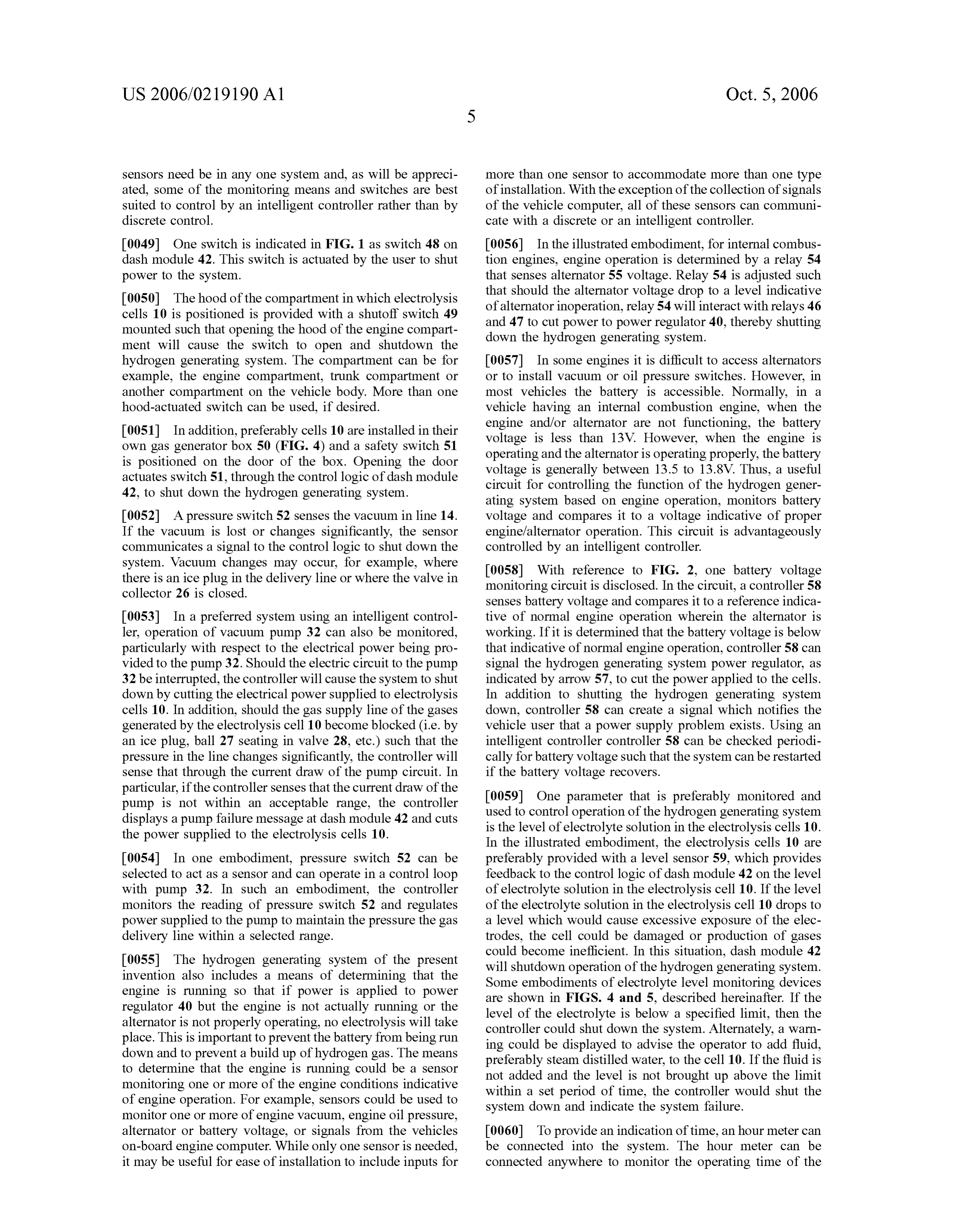
arrangement for monitoring the integrity of the output circuit 0.066. The electrolysis cell 10 is provided with a cap 74 from the regulator. The arrangement can sense a cell circuit that is welded to the sidewall once the components of the current or voltage. Referring to FIGS. 3A and 3B, power electrolysis cell have been assembled. The cap 74 is pro regulator 40 provides power to electrolysis cells 10, which vided with an outlet 75 to which the tubing 14 is connected. are connected in series. A break in the circuit Such as by Cell 10 also has a fill plug 76 which is removable to allow boiling dry, connections loosing contact, etc. can be detected the addition of distilled water or electrolyte solution to the by monitoring voltage (FIG. 3A) or current (FIG.3B) in the cell through a fill port 77. Preferably, the fill plug 76 also circuit. The useful values or ranges for current or Voltage in incorporates a pressure release mechanism to provide for the system can be determined based on system design. relief of the pressure within the cell 10 should the interior 0062 Referring particularly to FIG. 3A, a voltage sensor pressure increase beyond a set limit. 60 can monitor voltage between the last two cells of the 0067. A mesh layer 78 fills an upper area of the cell. circuit. To monitor the Voltage, one useful arrangement Gases produced by the cell pass through mesh 78 to outlet includes a transistor or comparator 61 that operates as a 75 and, in so doing, are dewatered by the mesh. Fill port 77 switch. When voltage is sensed in the circuit, an LED 62 on, extends down through the mesh layer so that, during filling, for example, the dash module is illuminated. When no electrolyte does not saturate the mesh. Voltage is sensed, transistor 61 Switches the circuit so that
LED 62 does not illuminate. Of course, various modifica 0068. The electrolysis cell 10 is provided with an elec tions can be made to this circuit with a similar result. For trode assembly 79, which is described in detail in U.S. example, LED 62 can be replaced with an automatic control application Ser. No. 09/719,976. The electrodes that make that can shut down system operation or the transistor can be up the electrode assembly are provided as a monocell, replaced with an intelligent system. monopolar assembly of an anode and a cathode. The outside cathode and anode electrode plates are provided with adapt 0063 Of course, the voltage sensing arrangement of FIG. ers 80 for electrical connection to terminals 70. 3A will not sense an open circuit in the last cell of the series or in the connection to ground. Thus, alternatively, a current 0069. The materials from which the electrode assembly is sensing arrangement can be used to determine if the cells are constructed are selected to minimize the effects of different being powered. A current sensing device 64. Such as a Hall coefficients of expansion of the materials, withstand strong effect sensor, is positioned anywhere along the circuit, as corrosive action of the electrolyte solution and provide indicated in phantom. A sensed current outside of a desirable effective and efficient electrolysis process. Thus, preferably, range or a no-current condition signal because of a break the electrode plates are a Suitable stainless steel material, anywhere along the circuit is passed to the controller for most preferably nickel plated stainless steel. communication to the user, for example, through the dash 0070 The electrolyte solution utilized within the elec module. This can be done easily via software. trolysis cell 10 is preferably a basic aqueous solution to 0064 Monitoring the temperature of power regulator 40 provide for increased efficiency of the electrolysis reaction. is sometimes also useful. In particular, if the power regulator Preferably, the solution is also adjusted to remain in solution heats up beyond acceptable temperatures, the feed back form and not freeze at extremely low temperatures, down to components such as shunts therein can give false readings -40° or more. Most preferably, the electrolyte solution is a or, in extreme situations, contacts in the power regulator can 20 to 30% KOH solution.
be damaged and destroyed, such that the power regulator 0071 FIG. 4 illustrates one electrolyte level monitoring burns out. Thus, another sensor useful in the present inven sensor useful in the present invention. The level monitoring tion is a temperature transducer on the circuit board of the sensor includes a rigid tube 82 installed through an opening power regulator. The controller can monitor the power in the upper cap 74. Tube 82 is held in position by a bolt 85 regulator temperature, as indicated by the temperature trans ducer, and control output to the power regulator to maintain threaded down on a threaded portion of the tube. Tube 82 has the temperature within an acceptable range. Alternatively or mounted thereon an upper stop 86 and a lower stop 87. in addition, the controller can use temperature information Slidably mounted therebetween is a float 88. Float 88 is to correct signals from the feedback components. selected to float on the electrolyte solution to be used in the cell and is free to ride up and down tube 82 between stops 0065. Many electrolysis cell types are useful in the 86 and 87. Sufficient clearance must be provided between present invention. Referring to FIG. 4, in one embodiment tube 82 and float 88 such that the float does not catch on the the electrolysis cell 10 utilized in the hydrogen generating tube and does not get jammed even in the presence of system of the present invention is similar to the cell granular debris which may accumulate in electrolyte solu described in detail in U.S. application Ser. No. 09/719,976, tion, over time. Tube 82 houses a circuit, as indicated by also known as WO/00/00671 published Jan. 6, 2000 the conductor 89, connected to a low level indicator such as an
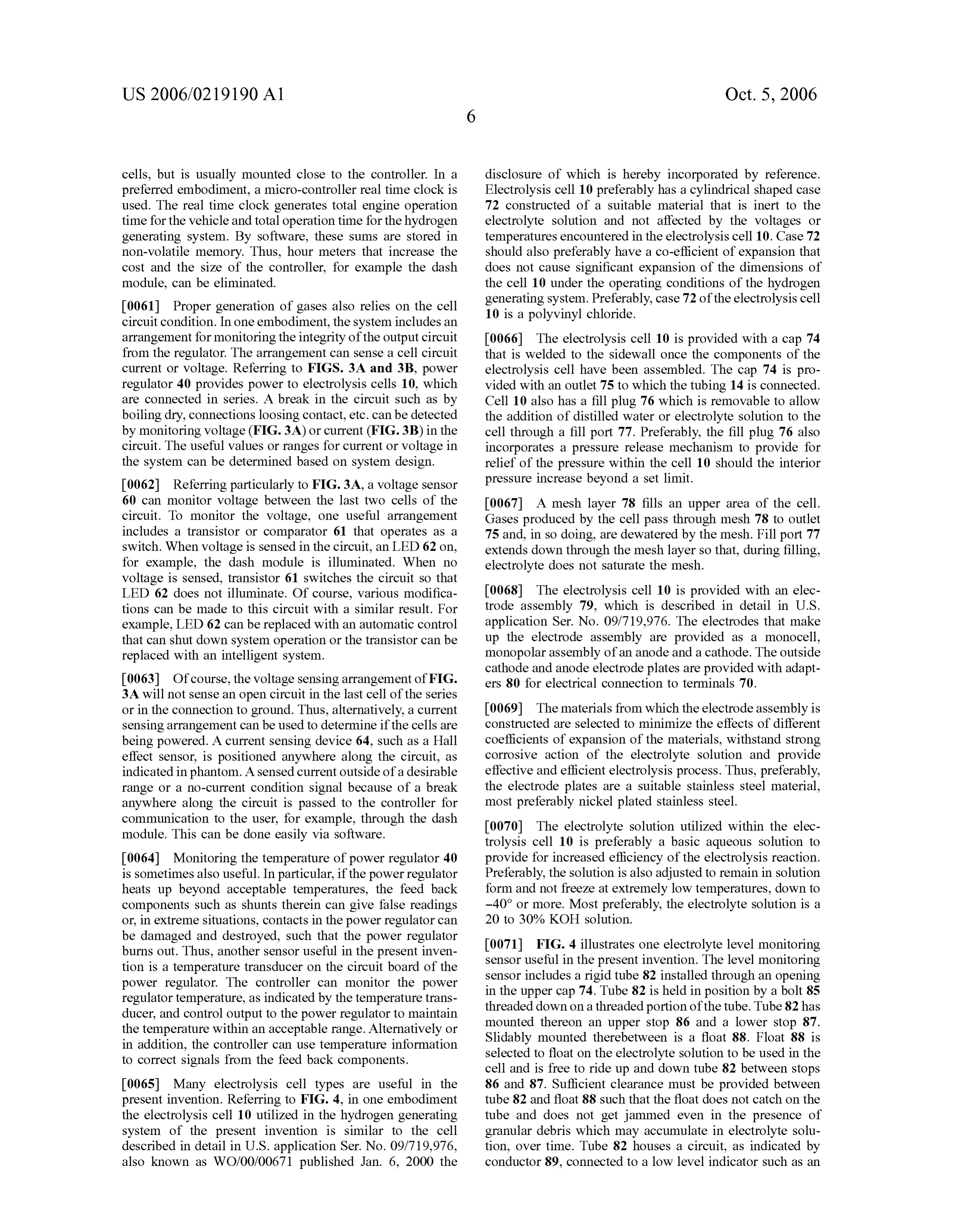
Page 13
US 2006/0219 190 A1 Oct. 5, 2006
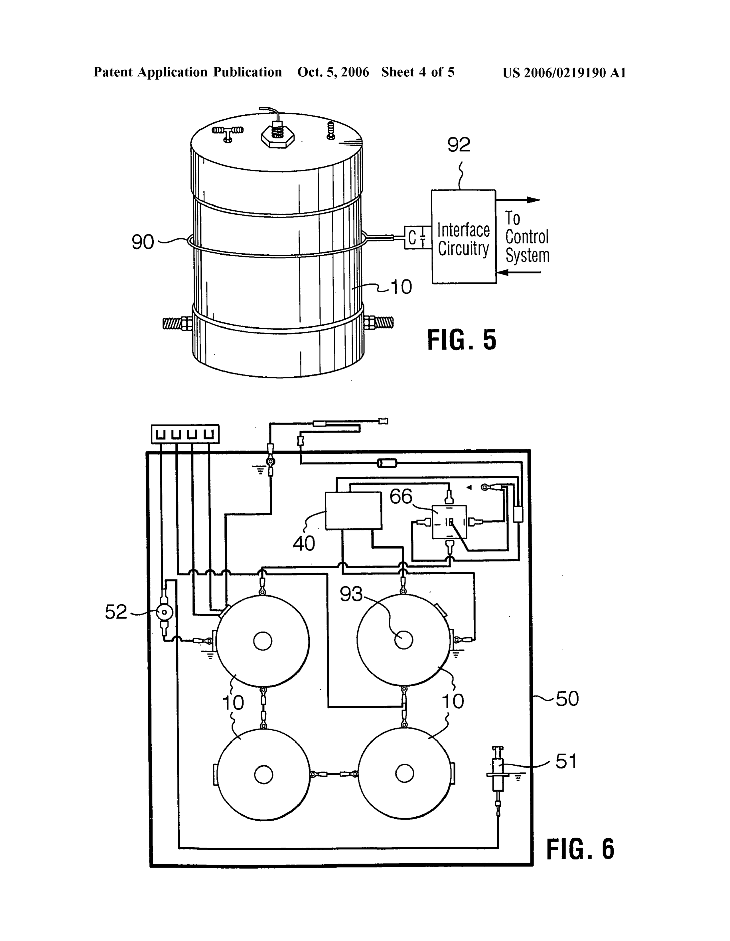
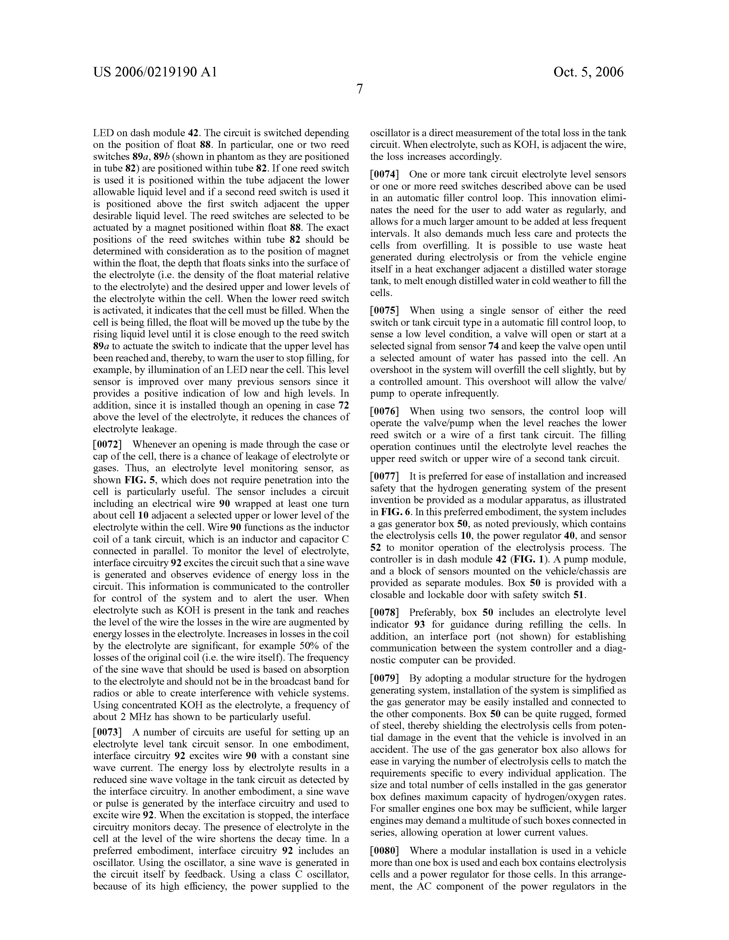
LED on dash module 42. The circuit is switched depending oscillator is a direct measurement of the total loss in the tank on the position of float 88. In particular, one or two reed circuit. When electrolyte, such as KOH, is adjacent the wire, switches 89a, 89b (shown in phantom as they are positioned the loss increases accordingly.
in tube 82) are positioned within tube 82. If one reed switch 0074. One or more tank circuit electrolyte level sensors is used it is positioned within the tube adjacent the lower or one or more reed switches described above can be used allowable liquid level and if a second reed switch is used it in an automatic filler control loop. This innovation elimi is positioned above the first switch adjacent the upper nates the need for the user to add water as regularly, and desirable liquid level. The reed switches are selected to be allows for a much larger amount to be added at less frequent actuated by a magnet positioned within float 88. The exact intervals. It also demands much less care and protects the positions of the reed switches within tube 82 should be cells from overfilling. It is possible to use waste heat determined with consideration as to the position of magnet generated during electrolysis or from the vehicle engine within the float, the depth that floats sinks into the surface of itself in a heat exchanger adjacent a distilled water storage the electrolyte (i.e. the density of the float material relative tank, to melt enough distilled water in cold weather to fill the to the electrolyte) and the desired upper and lower levels of cells.
the electrolyte within the cell. When the lower reed switch is activated, it indicates that the cell must be filled. When the 0075) When using a single sensor of either the reed cell is being filled, the float will be moved up the tube by the Switch or tank circuit type in a automatic fill control loop, to rising liquid level until it is close enough to the reed Switch sense a low level condition, a valve will open or start at a 89a to actuate the switch to indicate that the upper level has selected signal from sensor 74 and keep the valve open until been reached and, thereby, to warn the user to stop filling, for a selected amount of water has passed into the cell. An example, by illumination of an LED near the cell. This level overshoot in the system will overfill the cell slightly, but by sensor is improved over many previous sensors since it a controlled amount. This overshoot will allow the valve? provides a positive indication of low and high levels. In pump to operate infrequently.
addition, since it is installed though an opening in case 72 0076. When using two sensors, the control loop will above the level of the electrolyte, it reduces the chances of operate the valve?pump when the level reaches the lower electrolyte leakage.
reed switch or a wire of a first tank circuit. The filling 0072. Whenever an opening is made through the case or operation continues until the electrolyte level reaches the cap of the cell, there is a chance of leakage of electrolyte or upper reed Switch or upper wire of a second tank circuit. gases. Thus, an electrolyte level monitoring sensor, as shown FIG. 5, which does not require penetration into the 0077. It is preferred for ease of installation and increased cell is particularly useful. The sensor includes a circuit safety that the hydrogen generating system of the present including an electrical wire 90 wrapped at least one turn invention be provided as a modular apparatus, as illustrated about cell 10 adjacent a selected upper or lower level of the in FIG. 6. In this preferred embodiment, the system includes electrolyte within the cell. Wire 90 functions as the inductor a gas generator box 50, as noted previously, which contains coil of a tank circuit, which is an inductor and capacitor C the electrolysis cells 10, the power regulator 40, and sensor connected in parallel. To monitor the level of electrolyte, 52 to monitor operation of the electrolysis process. The interface circuitry 92 excites the circuit such that a sine wave controller is in dash module 42 (FIG. 1). A pump module, is generated and observes evidence of energy loss in the and a block of sensors mounted on the vehicle/chassis are circuit. This information is communicated to the controller provided as separate modules. Box 50 is provided with a for control of the system and to alert the user. When closable and lockable door with safety switch 51. electrolyte such as KOH is present in the tank and reaches 0078 Preferably, box 50 includes an electrolyte level the level of the wire the losses in the wire are augmented by indicator 93 for guidance during refilling the cells. In energy losses in the electrolyte. Increases in losses in the coil addition, an interface port (not shown) for establishing by the electrolyte are significant, for example 50% of the communication between the system controller and a diag losses of the original coil (i.e. the wire itself). The frequency nostic computer can be provided.
of the sine wave that should be used is based on absorption to the electrolyte and should not be in the broadcast band for 0079. By adopting a modular structure for the hydrogen radios or able to create interference with vehicle systems. generating system, installation of the system is simplified as Using concentrated KOH as the electrolyte, a frequency of the gas generator may be easily installed and connected to about 2 MHZ has shown to be particularly useful. the other components. Box 50 can be quite rugged, formed of steel, thereby shielding the electrolysis cells from poten 0073. A number of circuits are useful for setting up an tial damage in the event that the vehicle is involved in an electrolyte level tank circuit sensor. In one embodiment, accident. The use of the gas generator box also allows for interface circuitry 92 excites wire 90 with a constant sine ease in varying the number of electrolysis cells to match the wave current. The energy loss by electrolyte results in a requirements specific to every individual application. The reduced sine wave Voltage in the tank circuit as detected by size and total number of cells installed in the gas generator the interface circuitry. In another embodiment, a sine wave box defines maximum capacity of hydrogen/oxygen rates. or pulse is generated by the interface circuitry and used to For Smaller engines one box may be sufficient, while larger excite wire 92. When the excitation is stopped, the interface engines may demand a multitude of such boxes connected in circuitry monitors decay. The presence of electrolyte in the series, allowing operation at lower current values. cell at the level of the wire shortens the decay time. In a preferred embodiment, interface circuitry 92 includes an 0080 Where a modular installation is used in a vehicle oscillator. Using the oscillator, a sine wave is generated in more than one box is used and each box contains electrolysis the circuit itself by feedback. Using a class C oscillator, cells and a power regulator for those cells. In this arrange because of its high efficiency, the power supplied to the ment, the AC component of the power regulators in the
Page 14
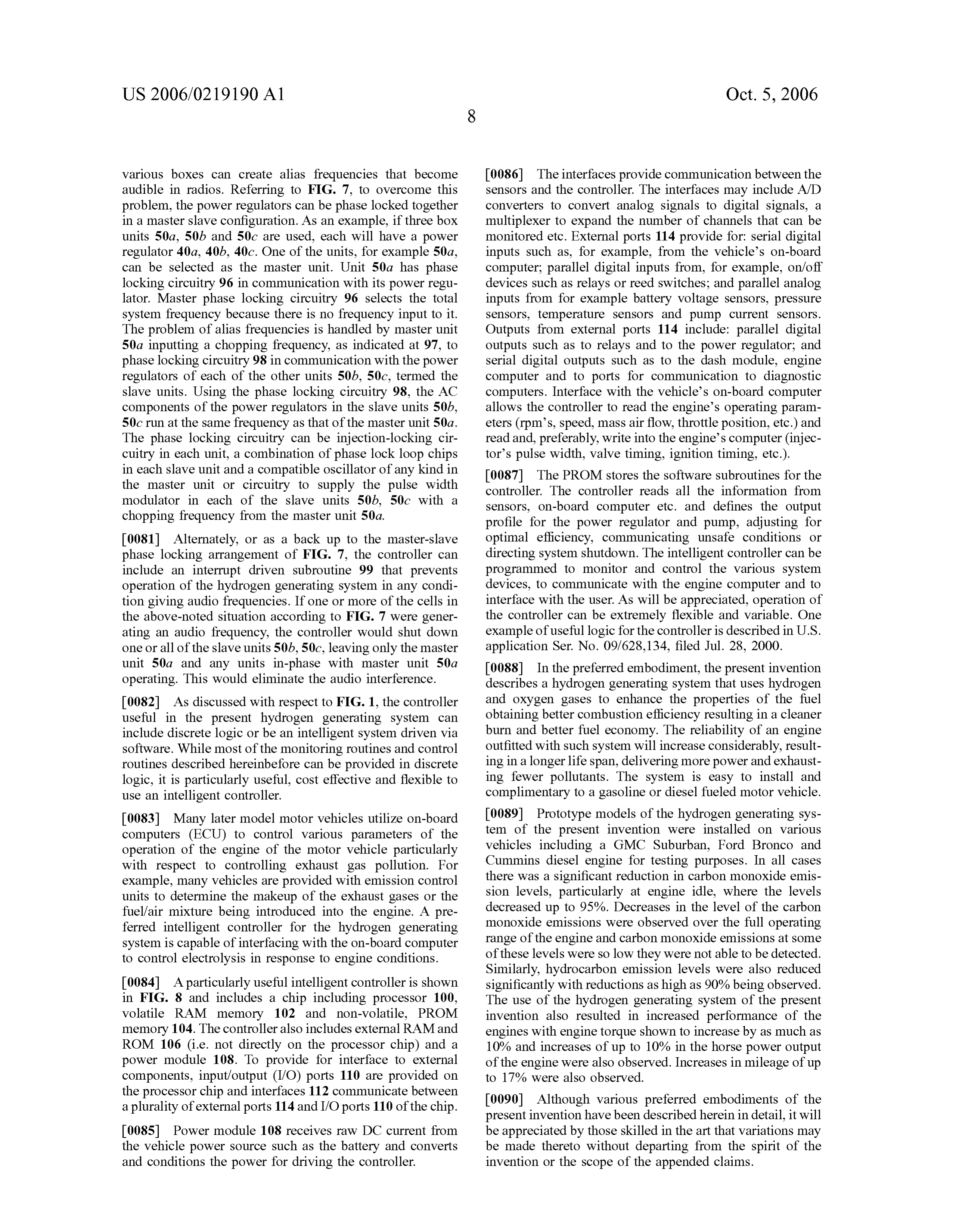
US 2006/0219 190 A1 Oct. 5, 2006
various boxes can create alias frequencies that become 0086) The interfaces provide communication between the audible in radios. Referring to FIG. 7, to overcome this sensors and the controller. The interfaces may include A/D problem, the power regulators can be phase locked together converters to convert analog signals to digital signals, a in a master slave configuration. As an example, if three box multiplexer to expand the number of channels that can be units 50a, 50b and 50c are used, each will have a power monitored etc. External ports 114 provide for: serial digital regulator 40a, 40b, 40c. One of the units, for example 50a, inputs such as, for example, from the vehicle's on-board can be selected as the master unit. Unit 50a has phase computer, parallel digital inputs from, for example, on/off locking circuitry 96 in communication with its power regu devices Such as relays or reed Switches; and parallel analog lator. Master phase locking circuitry 96 selects the total inputs from for example battery Voltage sensors, pressure system frequency because there is no frequency input to it. sensors, temperature sensors and pump current sensors. The problem of alias frequencies is handled by master unit Outputs from external ports 114 include: parallel digital 50a inputting a chopping frequency, as indicated at 97, to outputs Such as to relays and to the power regulator; and phase locking circuitry 98 in communication with the power serial digital outputs such as to the dash module, engine regulators of each of the other units 50b, 50c, termed the computer and to ports for communication to diagnostic slave units. Using the phase locking circuitry 98, the AC computers. Interface with the vehicle's on-board computer components of the power regulators in the slave units 50b, allows the controller to read the engine's operating param 50c run at the same frequency as that of the master unit 50a. eters (rpms, speed, mass air flow, throttle position, etc.) and The phase locking circuitry can be injection-locking cir read and, preferably, write into the engine's computer (injec cuitry in each unit, a combination of phase lock loop chips tor's pulse width, valve timing, ignition timing, etc.). in each slave unit and a compatible oscillator of any kind in 0087. The PROM stores the software subroutines for the the master unit or circuitry to supply the pulse width controller. The controller reads all the information from modulator in each of the slave units 50b, 50c with a sensors, on-board computer etc. and defines the output chopping frequency from the master unit 50a. profile for the power regulator and pump, adjusting for 0081 Alternately, or as a back up to the master-slave optimal efficiency, communicating unsafe conditions or phase locking arrangement of FIG. 7, the controller can directing system shutdown. The intelligent controller can be include an interrupt driven subroutine 99 that prevents programmed to monitor and control the various system operation of the hydrogen generating system in any condi devices, to communicate with the engine computer and to tion giving audio frequencies. If one or more of the cells in interface with the user. As will be appreciated, operation of the above-noted situation according to FIG. 7 were gener the controller can be extremely flexible and variable. One ating an audio frequency, the controller would shut down example of useful logic for the controller is described in U.S. one or all of the slave units 50b, 50c, leaving only the master application Ser. No. 09/628,134, filed Jul. 28, 2000. unit 50a and any units in-phase with master unit 50a 0088. In the preferred embodiment, the present invention operating. This would eliminate the audio interference. describes a hydrogen generating system that uses hydrogen 0082. As discussed with respect to FIG. 1, the controller and oxygen gases to enhance the properties of the fuel useful in the present hydrogen generating system can obtaining better combustion efficiency resulting in a cleaner include discrete logic or be an intelligent system driven via burn and better fuel economy. The reliability of an engine software. While most of the monitoring routines and control outfitted with such system will increase considerably, result routines described hereinbefore can be provided in discrete ing in a longer life span, delivering more power and exhaust logic, it is particularly useful, cost effective and flexible to ing fewer pollutants. The system is easy to install and use an intelligent controller. complimentary to a gasoline or diesel fueled motor vehicle. 0083. Many later model motor vehicles utilize on-board 0089 Prototype models of the hydrogen generating sys computers (ECU) to control various parameters of the tem of the present invention were installed on various operation of the engine of the motor vehicle particularly vehicles including a GMC Suburban, Ford Bronco and with respect to controlling exhaust gas pollution. For Cummins diesel engine for testing purposes. In all cases example, many vehicles are provided with emission control there was a significant reduction in carbon monoxide emis units to determine the makeup of the exhaust gases or the sion levels, particularly at engine idle, where the levels fuel/air mixture being introduced into the engine. A pre decreased up to 95%. Decreases in the level of the carbon ferred intelligent controller for the hydrogen generating monoxide emissions were observed over the full operating system is capable of interfacing with the on-board computer range of the engine and carbon monoxide emissions at Some to control electrolysis in response to engine conditions. of these levels were so low they were notable to be detected. Similarly, hydrocarbon emission levels were also reduced 0084. A particularly useful intelligent controller is shown significantly with reductions as high as 90% being observed. in FIG. 8 and includes a chip including processor 100, The use of the hydrogen generating system of the present volatile RAM memory 102 and non-volatile, PROM invention also resulted in increased performance of the memory 104. The controller also includes external RAM and engines with engine torque shown to increase by as much as ROM 106 (i.e. not directly on the processor chip) and a 10% and increases of up to 10% in the horse power output power module 108. To provide for interface to external of the engine were also observed. Increases in mileage of up components, input/output (I/O) ports 110 are provided on to 17% were also observed.
the processor chip and interfaces 112 communicate between 0090 Although various preferred embodiments of the a plurality of external ports 114 and I/O ports 110 of the chip. present invention have been described herein in detail, it will 0085 Power module 108 receives raw DC current from be appreciated by those skilled in the art that variations may the vehicle power source such as the battery and converts be made thereto without departing from the spirit of the and conditions the power for driving the controller. invention or the scope of the appended claims.
Page 15
US 2006/0219 190 A1 Oct. 5, 2006
1. (canceled) 11. The hydrogen generating system of claim 5 wherein 2. (canceled) the Supplemental gas is introduced to the inlet tubing 3. (canceled) between a flame arrestor and the vacuum pump. 4. (canceled) 12. (canceled) 5. A hydrogen generating system for use in an internal 13. (canceled) combustion engine of a vehicle for increasing the efficiency of the engine and decreasing emissions from the engine, the 14. A hydrogen generating system for use in an internal hydrogen generating System comprising: combustion engine of a vehicle for increasing the efficiency of the engine and decreasing emissions from the engine, the at least one electrolysis cell for generating hydrogen and hydrogen generating System comprising: oxygen gases by electrolysis of an aqueous solution;
a power source for providing electrical power to the an plurality of electrolysis cells for generating hydrogen electrolysis cell; and oxygen gases by electrolysis of an aqueous solu tion, the electrolysis cells being electrically connected an outlet flow means for introducing the generated gases in series;
into the intake manifold system of an internal combus tion engine, the outlet flow means including a vacuum a power source for providing electrical power to the pump for drawing the generated gases under vacuum electrolysis cells through an output circuit; toward the internal combustion engine, the vacuum an outlet flow means for introducing the generated gases pump having an inlet tubing and an outlet tubing and a vacuum control arrangement for conveying Supplemen into the intake manifold system of the internal com tal gas from gas source and introducing the Substantial bustion engine;
gases to the generated gases in the inlet tubing to reduce a monitoring means for monitoring the operating condi the vacuum generated by the vacuum pump; tions of the hydrogen generating system, the monitor a monitoring means for monitoring the operating condi ing means including sensor for monitoring the integrity tions of the hydrogen generating system; and of the output circuit from the power source; and a control means in communication with the monitoring a control means in communication with the monitoring means and adapted to control the operation of the means and adapted to control the operation of the hydrogen generating system in response to the moni hydrogen generating system in response to the moni toring means. toring means, the control means including means in 6. The hydrogen generating system of claim 5 wherein the communication with the sensor for controlling opera gas source is atmospheric air. tion of the hydrogen generating system based on the 7. The hydrogen generating system of claim 5 wherein integrity of the output circuit. Supplemental gas is heated over ambient air temperature, 15. The hydrogen generating system of claim 14 wherein filtered and/or dried.
8. The hydrogen generating system of claim 5 wherein the the plurality of electrolysis cells includes a penultimate and gas source is the exhaust gas manifold of the vehicle. last cells in the series and the sensor monitors the Voltage in 9. The hydrogen generating system of claim 5 wherein the the electrical connection between the penultimate and last cells.
gas source is the air intake of the vehicle downstream of the mass air flow sensor. 16. The hydrogen generating system of claim 14 wherein 10. The hydrogen generating system of claim 5 wherein the sensor monitors current in the output circuit. the vacuum control arrangement includes a valve for con trolling the flow of Supplemental gas into the inlet tubing.
Provenance
- Collection
- Patents citing this work
- Original assignee
- Hy Drive Technologies Ltd
- Pages
- 15
- Method
- pdftotext (the PDF's own text layer) + pdftoppm 300dpi page scans
- Patent office record
- patents.google.com →
- Source
- Google Patents citing-documents table
- Inventors
- Gabi Balan; Johnston Donald; Daniela Balan; Eugeniu Aldea; Mario De Souza; Hy Drive Technologies Ltd
- Published
- 2006-10-05
- Transcribed from
- patentimages.storage.googleapis.com →