patent · US3939806
Fuel regenerated non-polluting internal combustion engine
24 February 1976
Page 1 — bibliographic record
United States Patent (19) 11, 3,939,806 Bradley (45) Feb. 24, 1976 54 FUEL REGENERATED NON-POLLUTING 57) ABSTRACT
INTERNAL COMBUSTON ENGINE
An internal combustion engine in which heat is de 76) Inventor: Curtis E. Bradley, 4517 Calle rived from the engine cooling system and/or the ex Ventura, Phoenix, Ariz. 85018 haust to heat a working fluid in a closed circulatory 22 Filed: Apr. 1, 1974 system. This heat transforms the working fluid into a gas which is delivered to a turbine which drives agen (21) Appl. No.: 456,974 erator. The generator delivers DC current to an elec trolysis cell in which water is decomposed. The water 52 U.S. C. ................. 123/3; 123/1 A; 123141.21; is decomposed by the electric current into its oxygen 123/119 E; 123/DIG. 12 and hydrogen components. The oxygen is passed to 51) int. Cl.’.......................................... F02B 43/08 the air intake of the engine carburetors, while the hy 58) Field of Search..... 123/1 A, 3, DIG. 12, 119 E, drogen is conveyed to a carburetor therefor. Also in 123/4.1.2, 41.21, 121; 60/39.18 B cluded is a carburetor for conventional hydrocarbon fuels. The two carburetors are connected by linkage 56) References Cited which may be operated either manually or by pressure UNITED STATES PATENTS to vary the ratio of the carbureted fuels which are de livered to the engine.
1,380,183 5/1921 Boisen ......................... 123/DIG. 12 1490,975 4/1924 Howard.............................. 1231121 Certain auxiliary equipment is provided in the form of 1,827,1 13 10/1931 Sanftleben....................... 123141.21 an air-cooled condenser in the working fluid system, a 1966,345 7|1934 Harrell................................ 1231121 supply tank for the hydrocarbon fuel, which ordinarily 2,362,015 1 1/1944 Lundquist........................ 123141.21 is gasoline, a water supply tank, a tank for receiving 2,509,498 5/1950 Heyl............................. 123/DIG. 12 hydrogen under pressure, a pump for the hydrogen 2,633,707 4/1953 Hermitte et al................ 60/39.18 B fuel, a pump for the working fluid system, a pump 3,311,097 3/1967 Mittelstaedt... ... 123/DIG. 12 for delivering water from the water tank to the 3,362,883 1/1968 Wright........................ 123/DIG. 2 electrolysis cell and a hydrogen pump which passes 3,459,953 8/1969 Hughes et al................ 123/DIG. 12 hydrogen to the hydrogen carburetor and/or the 3,653,364 4/1972 Bogan..................................... 12313 hydrogen tank.
3,704,587 12/1972 Krieb et al. .................... 60/39.18 B 3,709,203 1/1973 Cettin et al............................. 12313 In a modification, power is derived from the engine 3,792,690 2/1974 Cooper................................... 123/3 exhaust to drive a turbo-generator which delivers DC FOREIGN PATENTS OR APPLICATIONS current to the electrolysis cell. This current may be 353,570 7/1931 United Kingdom............. 12311 19 E supplemented by that provided by a generator that is driven by a turbine powered by the working fluid of a
Primary Examiner-Charles J. Myhre system that is heated by the cooling system of the Assistant Examiner-David D. Reynolds engine.
Attorney, Agent, or Firm-John A. Robertson 5 Claims, 5 Drawing Figures
Page 2
Drawing sheet — no readable text.
Page 3
Drawing sheet — no readable text.
Page 4
Drawing sheet — no readable text.
Page 5
Drawing sheet — no readable text.
Page 6
working fluid as it is expanded into gases. This turbine
FUEL REGENERATED NON-POLLUTING generator system may be of the type commonly known INTERNAL COMBUSTION ENGINE as a Rankine Cycle.
The present invention relates to internal combustion 4. To provide, in an internal combustion engine of engines and is concerned primarily with the generation 5 the kind described, a generator which is driven by the of power derived from engine heat to produce an elec turbine and which generates a DC current which is tric current which decomposes water to provide hydro conducted to an electrolysis cell. gen which is used as fuel for the engine. 5. To provide, in conjunction with an internal com BACKGROUND OF THE INVENTION bustion engine of the type noted, a water supply tank 10 from which water is passed to the electrolysis cell.
At the present time, the public is confronted with two 6. To provide, in conjunction with an internal com basic problems related to the consumption of fuel in an bustion engine of the character aforesaid, a hydrogen internal combustion engine. One of these problems is tank into which hydrogen is introduced from the elec the pollution of the ambient atmosphere by the prod trolysis cell under pressure.
ucts of combustion. These noxious products are oxides 15 7. To provide, in an internal combustion engine of of nitrogen (NO), carbon monoxide (CO) and un the kind described, a conduit which conducts hydrogen burned hydrocarbons (HC). Of late, considerable at from the electrolysis cell and/or the hydrogen tank to a tention has been devoted in attempt to minimize if not hydrogen carburetor.
completely obviate these noxious products of combus 8. To provide, in an internal combustion engine of tion. 20 the type noted, a conduit for passing oxygen from the The other problem deals with the conservation of electrolysis cell to the air intake of the engine. fuel. The country is now faced with an energy shortage 9. To provide, in an internal combustion engine of and much effort has been directed to the broad object the character aforesaid, a fuel pump for conducting of regenerating fuel from the heat of the engine, with hydrocarbon fuel from a fuel tank to a carburetor, a the regenerated fuel being passed back to the engine 25 pump for the working fluid system, a pump for deliver for consumption therein. ing water from the water tank to the electrolysis cell, It is now a well recognized phenomenum that when and a pump for introducing hydrogen into the hydro hydrogen is used as a fuel in an internal combustion gen tank under pressure.
engine the noxious products of combustion which pol 10. To provide, in an internal combustion engine of lute the atmosphere are reduced to a high degree if not 30 the kind described, a turbo-generator that is powered completely eliminated. This has been found to be true by exhaust gases to provide DC current to an electroly not only when the hydrogen is the only fuel used, but sis cell.
also when the hydrogen is combined with conventional 11. To provide, in an internal combustion engine of hydrocarbon fuels such as gasoline, diesel oil and the the type noted, a second generator in addition to the like. 35 turbo-generator aforesaid, that is driven by a working The decomposition of water into its components of fluid that is heated by the engine cooling system. oxygen and hydrogen by passing an electric current Various other more detailed objects and advantages therethrough is also a now well recognized phenome of the invention, such as arise in connection with carry num. Other methods of decomposing water to provide ing out the above ideas in a practical embodiment will, oxygen have also been proposed. One of these is to pass 40 in part, become apparent and, in part, be hereafter water or steam into contact with heated ferrous balls. stated as the description of the invention proceeds. Moreover, it has been proposed to use hydrogen so generated as a fuel in internal combustion engines. SUMMARY OF THE INVENTION However, from the apparent lack of public acceptance of such technology, it is believed that this failure is due 45 The foregoing objects are achieved by providing an to the highly inefficient nature of such processes. internal combustion engine which includes a cooling The present invention is founded on the basic con System, a fuel intake manifold and an exhaust manifold cept of utilizing heat derived from an internal combus having an exhaust pipe extending therefrom, with a tion engine to generate electric power which decom circulatory system which derives heat from the cooling poses water to provide hydrogen which is used in the 50 system and the exhaust pipe for a working fluid which engine. Thus, air pollution is reduced or avoided to a may be water or freon. A turbine in a Rankine Cycle is large extent and energy is conserved. included in the working fluid system and is operated by OBJECTS OF THE INVENTION the gases derived from heating the working fluid. The working fluid system is closed and also includes a con
With the foregoing conditions in mind, the present 55 denser for converting the gaseous working fluid back to invention has in view the following objectives: its liquid form and a pump for circulating the working 1. To provide an internal combustion engine includ fluid. A generator is driven by the turbine and is con ing means for deriving heat from the engine, utilizing nected by appropriate conductors with an electrolysis this heat to generate an electric current, decomposing cell into which the water is introduced from a water water by passing the electric current therethrough to 60 Supply tank.
provide hydrogen, and then using the hydrogen as a Mounted on top of the engine in accordance with fuel in the engine. conventional practice is an air filter, and immediately 2. To provide, in an internal combustion engine of below this air filter are two carburetors which commu the type noted, a circulatory system for a working fluid nicate with the intake manifold of the engine. One of and which includes means for heating the working fluid 65 these carburetors is for conventional hydrocarbon fuel either from the engine cooling system and/or the en and the other is for hydrogen. The hydrocarbon fuel is gine exhaust. conducted from a supply tank therefor to the carbure 3. To provide, in an internal combustion engine of tor for hydrocarbon fuel through a conduit including a the character aforesaid, a turbine which is driven by the pump. Another conduit extends from the other carbu
Page 7
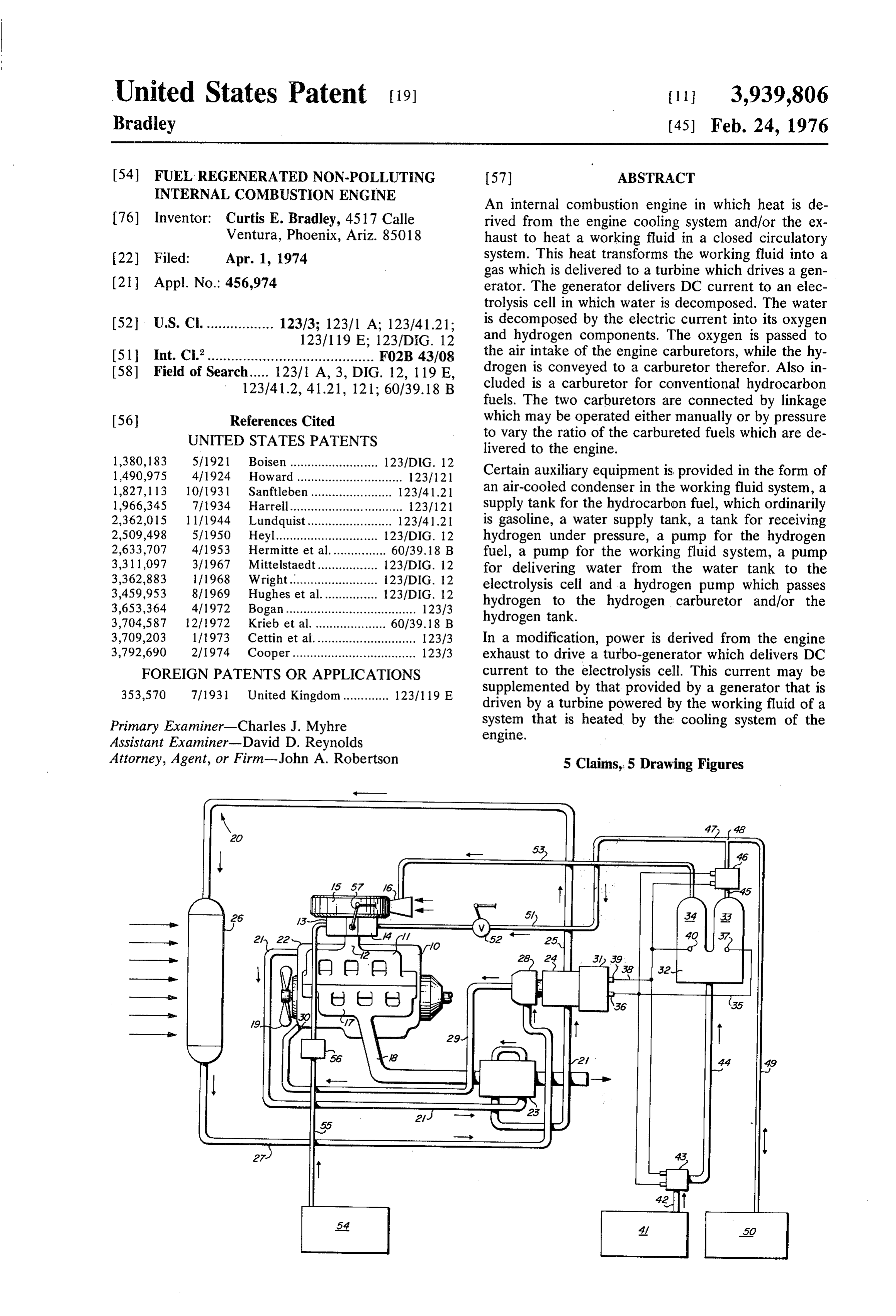
retor which is for hydrogen to that portion of the elec 13 for hydrocarbon fuel such as gasoline and a hydro trolysis cell in which hydrogen is collected. A pump gen carburetor or injector 14. Both of the carburetors connected to this portion of the cell is connected to a 13 and 14 communicate with stem 12. Mounted above conduit which extends both to the hydrogen carburetor carburetors 13 and 14 is an air filter 15 having an air and a tank for receiving hydrogen under pressure. A intake 16.
valve is included in this conduit and is operable to Carried by engine block 10 is an exhaust manifold 17 determine when hydrogen is delivered to the hydrogen from which extends an exhaust pipe 18. Engine block carburetor. - 10 includes a cooling system in accordance with ac The air filter includes an air intake and oxygen from 10 cepted practice and hence is not herein illustrated. the electrolysis cell is passed to this air intake where it However, a fan which may be considered as a part of is mixed with ambient air to provide oxygen-enriched the cooling system is illustrated at 19. air which is delivered to both carburetors. A closed circulatory system as in a Rankine Cycle for In a modification, a turbo-generator is driven directly a working fluid such as water or freon is designated by gases from the engine exhaust to provide DC current generally 20. It comprises a conduit 21 which is in heat to the electrolysis cell. This turbo-generator may be 5 conducting relation to the cooling system of the engine used alone or in combination with another generator at the point indicated at 22. It extends to and passes driven by a turbine which is powered by the working through a heat exchanger-23 which is disposed about fluid in a closed system that is heated by the engine exhaust pipe 18. From heat exchanger 23 conduit 21 is cooling system. - continued to a turbine 24 which is of the kind typified Now known internal combustion engines may be 20 by the Rankine Cycle. The working fluid which origi catalogued into three types. One is the conventional nally is in liquid form is converted into a gaseous state Otto cycle internal combustion engine now widely used by the heat derived from the cooling system of the in which the fuel is ignited by spark plugs. The second engine and the exhaust pipe and drives the turbine 24. is the well known diesel cycle engine in which the fuel From the latter, another conduit 25 extends to a con is ignited by compression of the intaken air gases. The 25 denser 26 which returns the working fluid to its liquid third is the Brayton cycle turbine type internal combus form. From condenser 26 another conduit 27 extends tion engine in which the fuel is burned at constant to a pump 28, and from the latter a conduit 29 extends pressure to drive a turbine rather than a piston. The to the engine block 10 at point 30, from whence it is present invention is susceptible of embodiment in the 30 connected to conduit 21 at point 22, being in heat internal combustion engines of each of the above noted conducting relation to the cooling system of the engine. types. The invention as applied to the first type is sum The operation of the closed system 20 may be sum marized in the preceding paragraphs. The apparatus marized by noting that the working fluid in liquid form required for a diesel engine is substantially the same, is delivered by pump 28 to that portion of the system with the notable exception that the carburetor for the 35 which is in heat conducting relation to the cooling hydrocarbon fuel and the fuel intake manifold are re system of the engine. Thus, the working fluid is heated placed by fuel injectors. In the case of the turbine en from the latter. It is further heated by heat exchanger gine, the working fluid circulatory system, turbine in 23 and this heat transfers the working fluid into a gase cluded therein, generator, electrolysis cell, fuel supply ous state which operates Rankine turbine 24. It is con tank, water supply tank, hydrogen tank and pumps 40 ducted in gaseous form to condenser 26 which returns therefor are the same as described in the preceding it to liquid form.
paragraphs. The difference between this embodiment An electric generator is indicated at 31 and an elec of the invention and the others resides in the construc trolysis cell at 32. The electrolysis cell is shown as tion of the turbine engine. having two legs 33 and 34. A conductor 35 connects a For a full and more complete understanding of the 45 terminal 36 of generator 31 to a terminal 37, while invention, reference may be had to the following de another conductor 38 extends from a terminal 39 of scription and the accompanying drawings, wherein: generator 31 to a terminal 40 of cell 32. Generator 31 FIG. 1 is a diagrammatic view illustrating the essen provides DC current.
tial elements of the present invention as applied to a A water supply tank is shown at 41. From the latter conventional internal combustion engine of the piston 50 upstands a pipe 42 which is connected to a pump 43. type in which the fuel is ignited by spark plugs; The latter is electrically driven by current derived from FIG. 2 is a diagrammatic view depicting the invention generator 31. From pump 43 a conduit 44 extends to as applied to a turbine engine; the lower portion of electrolysis cell 32 and is effective FIG. 3 is another diagrammatic view of the invention to introduce water into the cell. The direct current as incorporated into a diesel engine; passes through this water and decomposes the water FIG. 4 is a schematic view of a modification of the 55 into its components of hydrogen and oxygen. The hy diesel engine embodiment, and drogen collects in leg 33 and oxygen in leg 34. A pipe FIG. 5 is a schematic view of an embodiment includ 45 extends upwardly from hydrogen leg 33 and in ing a turbo-generator that is powered by exhaust gases. cluded therein is a pump 46 which is electrically driven
DESCRIPTION - FIRST EMBODIMENT,
from generator 31. Pipe 45 communicates with a cross 60 conduit 47 at point 48. From the latter, one side of
Referring now to the drawings, wherein like refer cross conduit 47 is connected to a conduit 49 which ence characters denote corresponding elements extends to a hydrogen tank 50. The other side of cross throughout the several views, and first to FIG. 1, an conduit 47 is connected to a hydrogen supply conduit internal combustion engine of the piston type in which 65 51 which communicates with hydrogen carburetor 14. the fuel is ignited by spark plugs is shown as including A valve 52 is included in hydrogen supply conduit 51. an engine block represented at 10. Mounted on engine It is evident that with generator 31 in operation, block 10 is a fuel intake manifold 11 having a main hydrogen is provided in leg 33 and with pump 46 in stem 12 on which is mounted a carburetor or injector operation, this hydrogen is either delivered to tank 50
Page 8
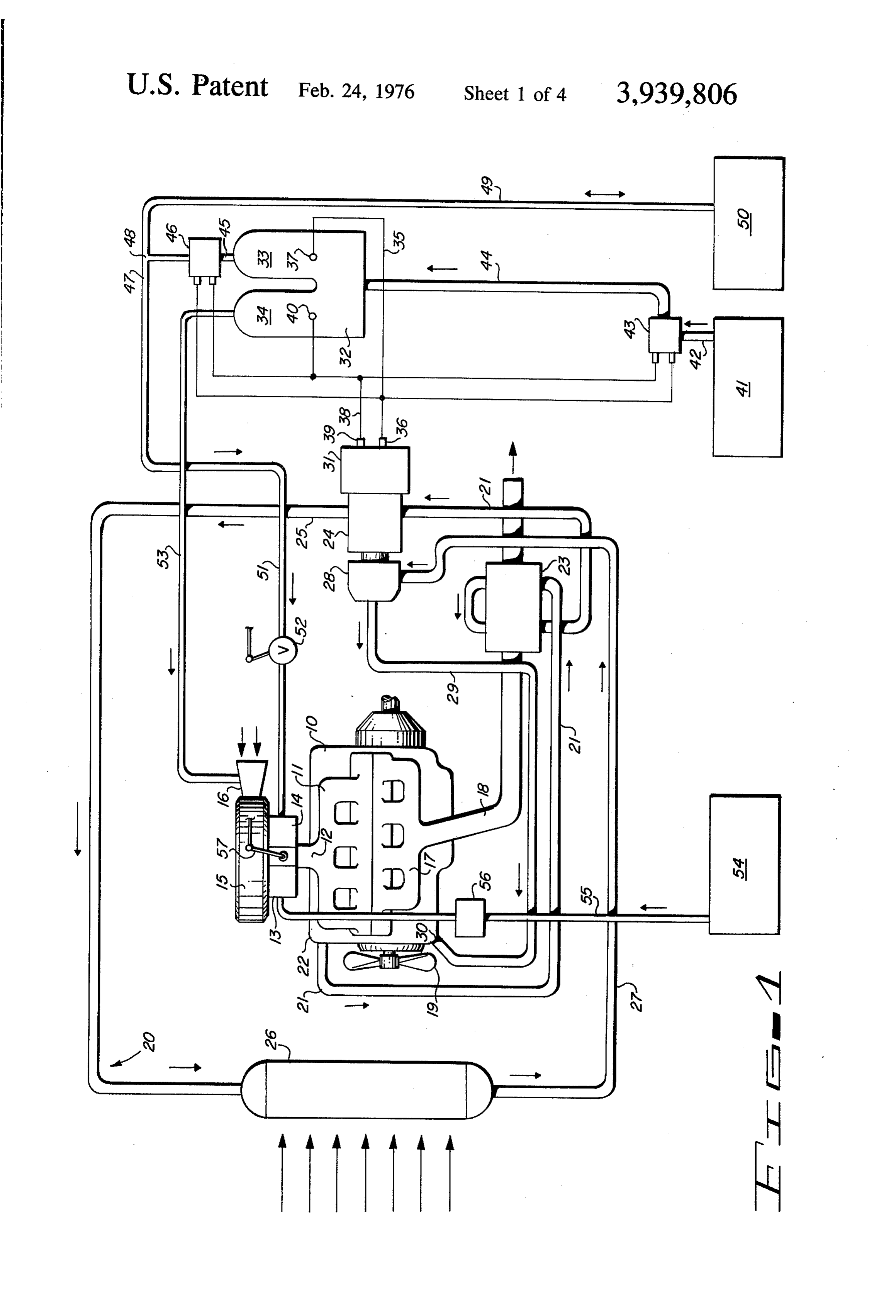
under pressure or to hydrogen carburetor 14, depend metering control 9 for hydrocarbon fuel is mounted ing on whether valve 52 is open or closed. over intake 60 as is a metering control 8 for hydrogen. While substantially all of the advantages of the pres An exhaust pipe 61 extends from casing 59 and dis ent invention are obtained if the oxygen resulting from posed thereabout is a heat exchanger 62, which corre the decomposition of the water is merely passed to the 5 sponds to the heat exchanger 23 of FIG. 1. An air in ambient atmosphere, some benefit will be derived take for engine 58 is represented at 63. The remaining therefrom because of oxygen having a higher density elements illustrated in FIG. 2, with some exceptions, than air which is mostly nitrogen, and which will deliver are the same as the corresponding elements of FIG. 1 more pounds of working fluid to the engine to some and have been so designated by like reference charac what compensate for the lost volume and weight flow 10 terS. . . .. . resulting from the use of hydrogen gas which is of low The working fluid system is somewhat different from density. Thus, a tube 53 is shown as extending from that of FIG. 1 and is designated generally 64. It com oxygen leg 34 of electrolysis cell 32 to air intake 16. prises a conduit 65 which extends from pump 28 and A fuel supply tank is shown at 54 and extending passes through heat exchanger 62 and emerges there therefrom is a feed pipe 55, the upper end of which is 15 from as a conduit 66 which goes to turbine 24. From connected to a hydrocarbon fuel carburetor 13. A fuel the latter, another conduit 67 extends to condenser 26. pump 56 is included in feed pipe 55 and is driven from Another conduit 68 connects condenser 26 with pump the engine in a conventional manner. . 28.
The operation of carburetors 13 and 14 may be con The main difference between the apparatus of that of trolled by a link 57 which may be manually operable or 20 FIG. 2 and that of FIG. 1 is the fact that heat is derived operable under pressure from hydrogen gas from con from the exhaust pipe 61 alone and not from a cooling duit 47. .... . . system of the engine.
OPERATION - FIRSTEMBODIMENT: , The operation of the turbine embodiment is substan tially the same as that described above in connection
While the manner in which the embodiment of FIG. 25 with FIG. 1, with the notable exception that the fuel 1 operates is believed to be evident from the illustration pump indicated at 56 includes a fuel metering control of the drawings and description of parts set forth above, governing the rate at which fuel is delivered from fuel it may be briefly outlined as follows: tank 54 to the fuel metering nozzle 9. Also, the hydro With hydrogen available from tank 50, the engine gen gas is delivered by conduit 51 to a fuel metering may be started on hydrogen alone. This may be accom- 30 nozzle 8.
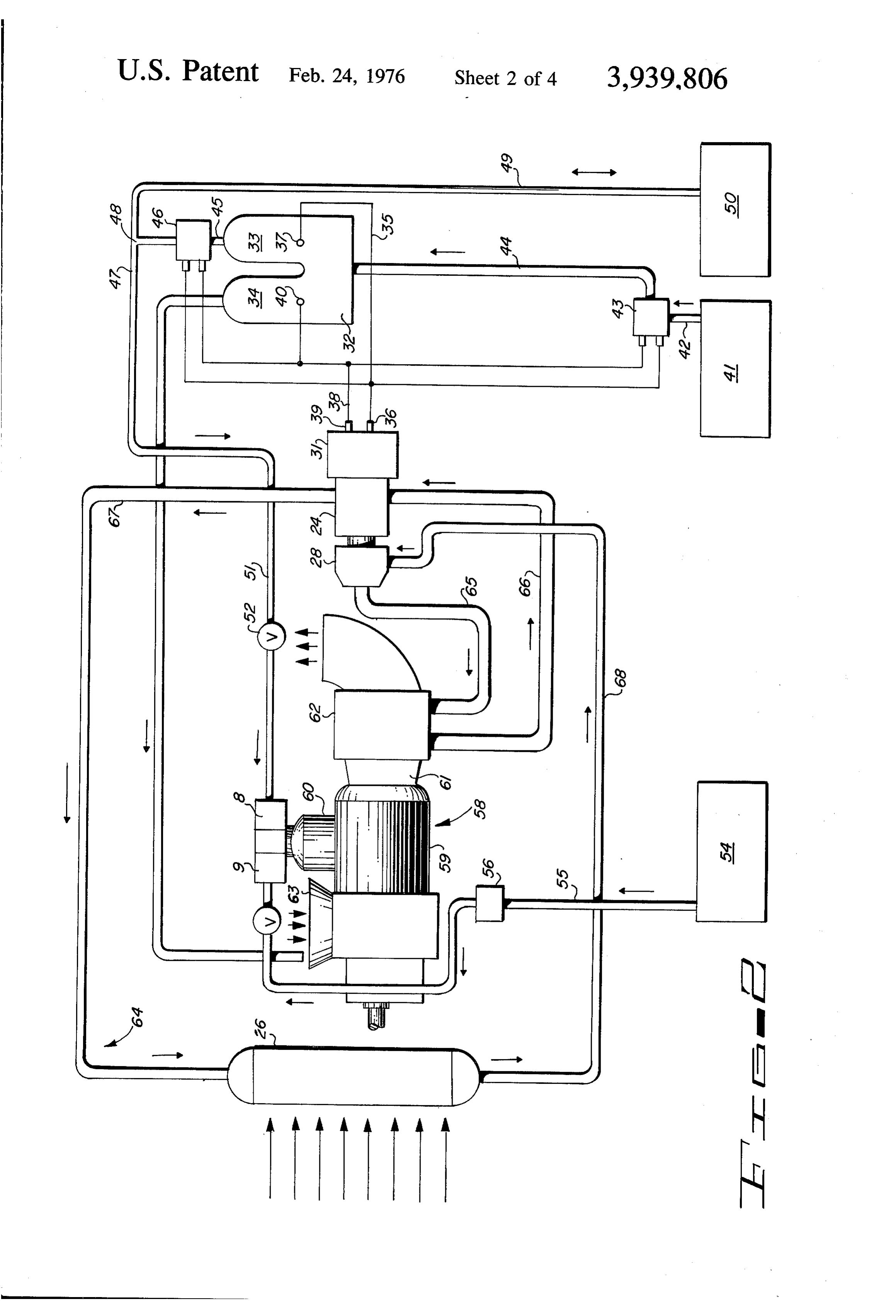
plished by opening valve 52 and adjusting linkage 57 so that no hydrocarbon fuel is initially delivered to fuel DESCRIPTION - THIRD EMBODIMENT intake manifold 11. Starting by hydrogen is preferred This embodiment is illustrated in FIG. 3 and shows because of its gaseous state and wide flammability the invention as applied to a diesel engine. The differ
ence between the diesel engine of FIG.3 and the con
With the engine in operation, the water in the cooling ventional engine of FIG. 1 resides in the elimination of system of the engine is heated and heat therefrom is the intake manifold 11 and carburetor 13 which are conducted to that portion of closed system 20 which is replaced by fuel injectors. Thus, manifold 69 is included in the engine. Exhaust gases are generated mounted on engine block 10 and receives diesel fuel and passed out of exhaust pipe 18. Heat is derived 40 from fuel injector pump and distribution supply tank 54 therefrom by heat exchanger 23 and transferred by through tube 55. Distribution tubes 70 extend from conduction to tube 21 of the closed system. manifold 69 to injection ports 71 in block 10. After the engine is started in operation, pump 56 is The operation of the diesel engine embodiment is the activated to deliver fuel to carburetor 13 and pump 28 same as that of the conventional internal combustion is operated to circulate the working fluid in system 20. 45 engine of FIG.1.
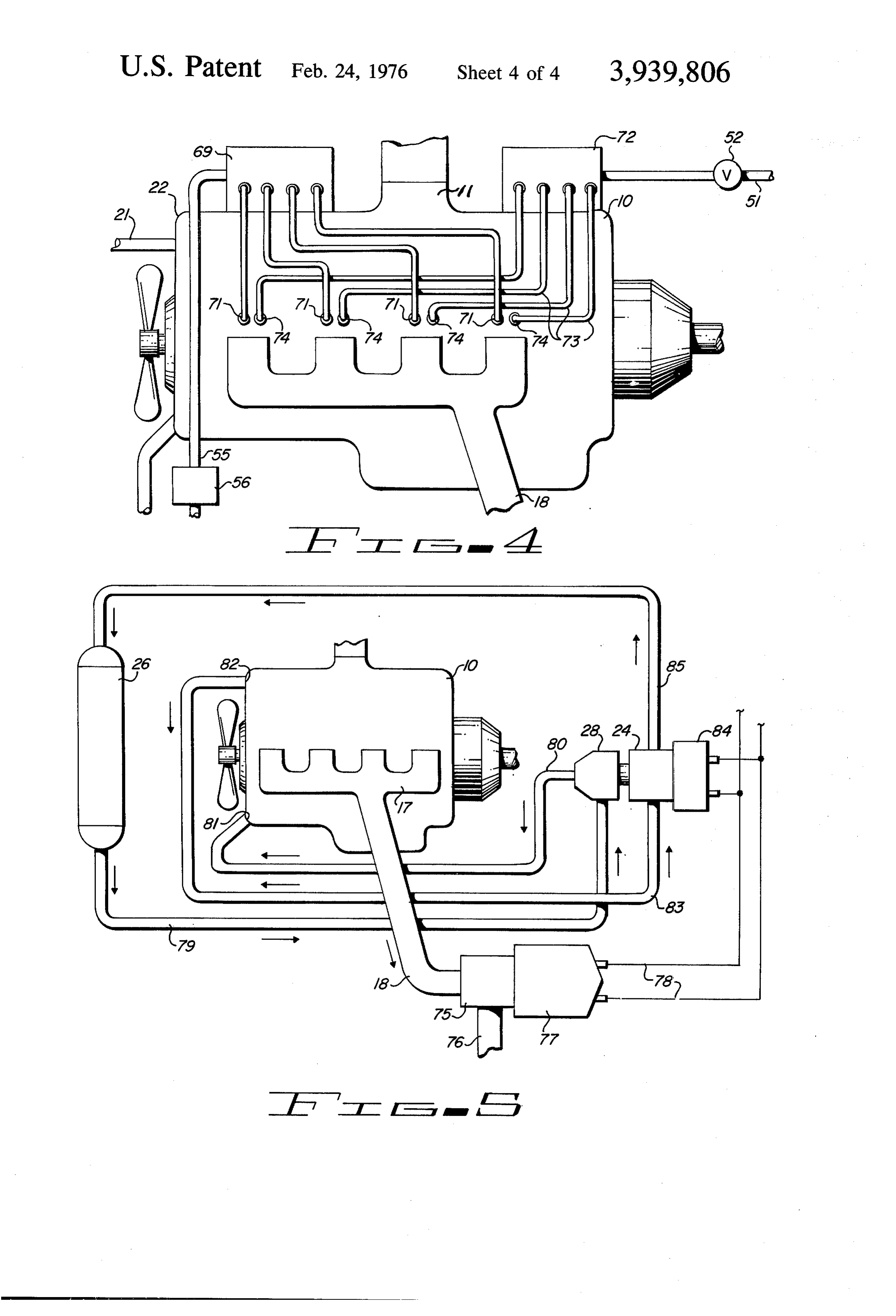
The heat transfers the liquid working fluid into a gase THE DIESEL ENGINE MODIFICATION ous form to operate turbine 24. The latter drives gener ator 31 to generate a direct current which is conducted Referring more particularly to FIG. 4, a modification to electrolysis cell 32. With generator 31 in operation, of the diesel engine embodiment is therein illustrated in punp 43 is also activated to deliver water from 41 to 50 which hydrogen gas is delivered directly to injection cell32. This water is decomposed by the direct current ports in the engine block rather than to the air intake. passing therethrough which results in decomposition of Conduit 51 is connected to a hydrogen fuel injector the water into its oxygen and hydrogen components. pump and distribution manifold 72 from which extend With generator 31 in operation, pump 46 is also four distribution tubes 73 which are connected at their activated to deliver the hydrogen from leg 33 of cell32 55 other ends to injection ports 74. either to hydrogen tank 50 or hydrogen carburetor 14. In diesel engines, the fuel is ignited by the heat de After the engine has been started, linkage 57 is ad rived from compressing the air. Hydrocarbon fuels justed to provide a desired ratio between the hydrocar have an ignition temperature which is much less than bon fuel and the hydrogen which is delivered to the that of hydrogen. Thus, hydrogen is delivered to the engine. 60 engine block only in combination with diesel fuel be DESCRIPTION - SECOND EMBODIMENT cause, once the fuel is ignited, it will in turn ignite the hydrogen gas.
This embodiment diagrammatically illustrates the THE TURBO-GENERATOR incorporation of the present invention into an internal combustion engine of the turbine type as illustrated in 65 Referring now to FIG. 5, a modification is therein FIG. 2. The turbine engine is represented at 58. It in illustrated in which a turbo-generator is driven directly cludes a casing 59 providing a combustion chamber by exhaust gases. Thus, engine block 10 is shown as into which fuel is introduced through an intake 60. A having the usual exhaust manifold 17 from which ex
Page 9
tends an exhaust pipe 18. Mounted on exhaust pipe 18 d. a heat exchanger disposed about said exhaust pipe and in communication therewith is a turbine 75 which and through which said closed system passes to is powered by the exhaust gases from pipe 18. Spent derive heat from the exhaust pipe and heat the exhaust gases pass out of turbine 75 at gas discharge working fluid;
76. A generator 77 is driven by a turbine 75. Generator e. a generator driven by said turbine to produce a DC 77 is connected by conductors 78 to the electrolysis electric current;
cell 32 which is not illustrated in FIG. 5 but corre f. an electrolysis cell containing water and connected sponds to cell 32 of FIGS. 1, 2 and 3. to said generator so that the DC current therefrom It is believed that the turbo-generator method of decomposes the water into oxygen and hydrogen; providing a direct current for the electrolysis cell when 10 g. cell;
a water tank for supplying water to said electrolysis used alone will present certain advantages. However, to h. a hydrogen carburetor on said engine block for improve its efficiency, it also may be used in combina delivering hydrogen to a combustion chamber in tion with a closed circuit working fluid system which derives heat from the cooling system of the engine, with 15 i. said block;
a conduit extending from said electrolysis cell to the heated working fluid driving the turbine of the said hydrogen carburetor which conveys hydrogen Rankine Cycle. Thus, as shown in FIG. 5, the closed from the cell to the carburetor; system for the working fluid comprises a conduit 79 j. a fuel tank for a hydrocarbon fuel; which extends from a condenser 26 to a pump 28 and k. a hydrocarbon fuel carburetor on said engine from the latter another conduit 80 extends to a point 81 20 block and connected to said hydrocarbon fuel where it enters and passes through engine block 10 in a tank, and position closely adjacent to the cooling system of the l. linkage connected to said carburetors and operable engine, whereby the working fluid in conduit 80 derives to vary the ratio of hydrogen and hydrocarbon fuel heat from the engine cooling system. Conduit 80 passes which is introduced into the combustion chamber out of the engine block at point 82 from which point it 25 of said engine block.
takes the form of conduit 83 which is connected to 2. The internal combustion engine of claim 1, to turbine 24. From turbine 24 another conduit 85 ex gether with a hydrogen tank with connections there tends to the other end of condenser 26. Generator 84 is from to said electrolysis cell to receive hydrogen there connected to electrolysis cell 32 in the same manner as from, a pump in said connections to generate pressure in the hydrogen which is delivered to said hydrogen illustrated and described in connection with FIGS. 1, 2 30 tank, and a valve in the conduit between the electroly and 3.
While preferred specific embodiments are herein flow sis cell and the hydrogen carburetor for controlling the disclosed, it is to be clearly understood that the inven of hydrogen therethrough. tion is not to be limited to the exact constructions, 35 whichThe
internal combustion engine of claim 1, in air filter is positioned over said carburetors mechanisms and devices illustrated and described be and includes an air intake, with the electrolysis cell cause various modifications of these details may be having a leg in which oxygen is collected, and a conduit provided in putting the invention into practice. extending from said leg to said air intake. What is Claimed is: 4. The internal combustion engine of claim 1 in 1. In an internal combustion engine, 40 which the engine block includes a cooling system and a. an engine block; the working fluid system passes through the engine b. an exhaust pipe extending from said block; block to acquire heat from said cooling system by con c. a closed system for a working fluid including a duction.
pump for circulating the working fluid through the 5. The internal combustion engine of claim 1 in system, a turbine which is operated by the working 45 which a conduit extends from the fuel tank to the hy fluid when in a gaseous state and a condenser for drocarbon fuel carburetor together with a pump in said returning the working fluid from a gaseous state to last mentioned conduit.
a liquid; :k k k is sk
Provenance
- Collection
- Cited prior art
- Original PDF
- patentimages.storage.googleapis.com →
- Filed
- 1974-04-01
- Pages
- 9
- Method
- pdftotext (the PDF's own text layer) + pdftoppm 300dpi page scans
- Source
- Google Patents bibliographic record
- Granted
- 1976-02-24
- Inventors
- Curtis E. Bradley
- Transcribed from
- patentimages.storage.googleapis.com →