patent · US5231954A
Hydrogen/oxygen fuel cell
3 August 1993
Page 1 — bibliographic record
United States Patent (19) 11 Patent Number: 5,231,954 Stowe 45) Date of Patent: Aug. 3, 1993 (54) HYDROGEN/OXYGEN FUEL CELL OTHER PUBLICATIONS 75 Inventor: Gene B. Stowe, Mesa, Ariz. Dahiya, Progress in Hydrogen Energy, D. Reidel Pub
73 Assignee: J. C. Conner, Scottsdale, Ariz. ; a Graham & Trotman, Hydrogen: Energy Vector of the part interest Future, (Mar. 24-25, 1981), pp.55-67.
Casper, Hydrogen Manufacture by Electrolysis, Ther mal Decomposition and Unusual Techniques, Noyes (21) Appl. No.: 926,039 Data Corp., (1978) pp. 111-207. Peavey, Fuel from Water, Merit Products, Inc., pp.
22 Filed: Aug. 5, 1992 15-50.
Kirk-Othmer, Encyclopedia of Chemical Technology, 51 int. C. .............................................. FO2B 43/08 3rd Edition, vol. 8, pp. 673-674, 679. 52 U.S. C. ............................... 123/3; 123/DIG. 12; Kirk-Othmer, Encyclopedia of Chemical Technology,
58) Field of Search .................. 123/3, DIG. 12, 1 A; Primary Examiner-E. Rollins Cross
Attorney, Agent, or Firm-Charles E. Cates; Frank T.
(56) References Cited Barber
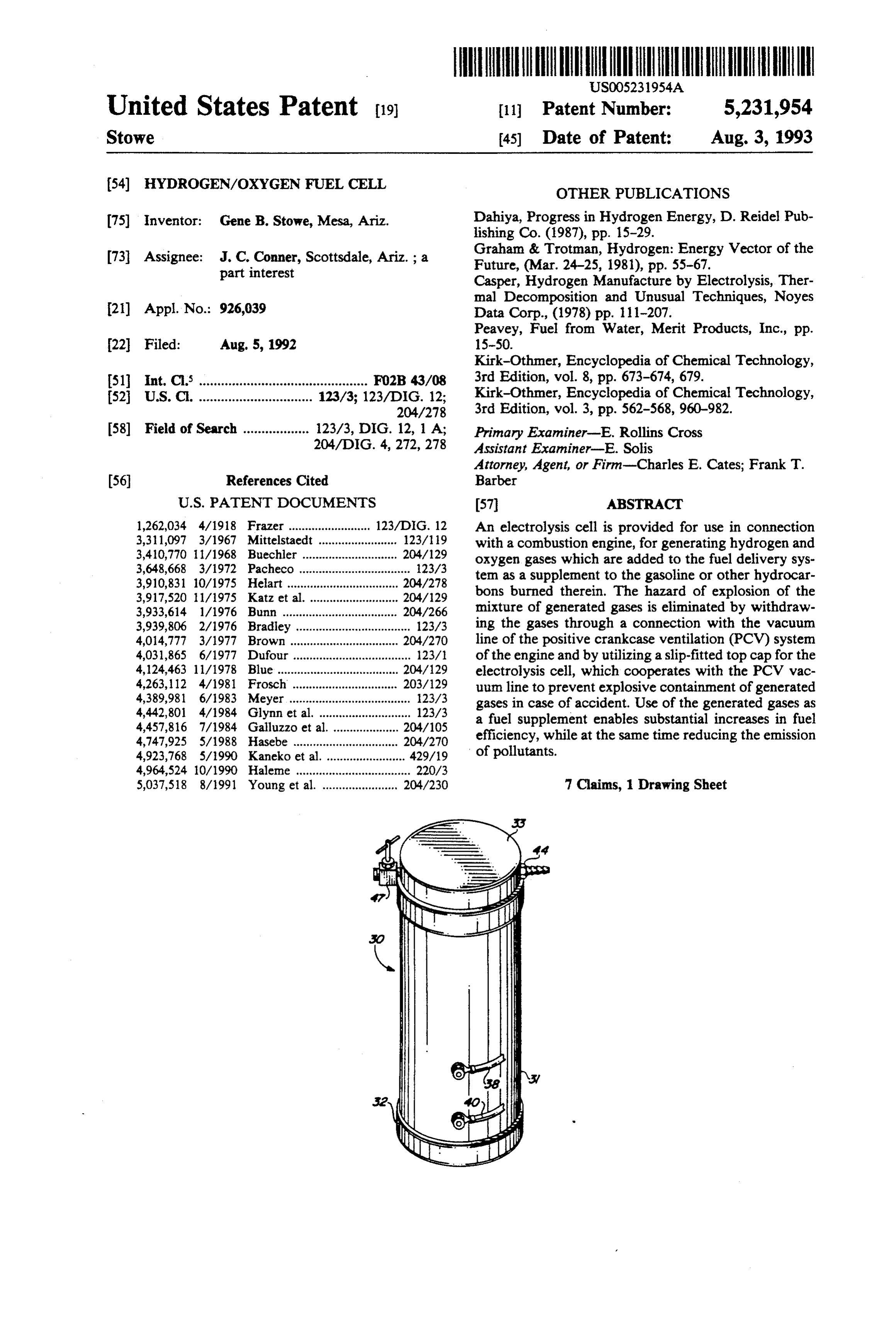
1,262,034 4/1918 Frazer ......................... 123/DIG. 12 An electrolysis cell is provided for use in connection 3,311,097 3/1967 Mittelstaedt ........................ 123/19 with a combustion engine, for generating hydrogen and 3,40,770 1 1/1968 Buechler ......... . 204/129 oxygen gases which are added to the fuel delivery sys 3,648,668 3/1972 Pacheco .................................. 123/3 ten as a supplement to the gasoline or other hydrocar 3,910,831 10/1975 Heart .................................. 204/278 3,917,520 1 1/1975 Katz et al. ........................... 2O4/29 bons burned therein. The hazard of explosion of the 3,933,614 1/1976 Bunn ........... ... 204/266 mixture of generated gases is eliminated by withdraw 3,939,806 2/1976 Bradley ................................... 123A3 ing the gases through a connection with the vacuum 4,014,777 3/1977 Brown..... . 204/270 line of the positive crankcase ventilation (PCV) system 4,031,865 6/1977 Dufour ................................... 123/ of the engine and by utilizing a slip-fitted top cap for the 4,124,463 11/1978 Blue ..................................... 204/129 electrolysis cell, which cooperates with the PCV vac 4,263,112 4/1981 Frosch ................................ 203/129 uum line to prevent explosive containment of generated 4,389,981 6/1983 Meyer ..................................... 1.23/3 gases in case of accident. Use of the generated gases as 4,442,801 4/1984 Glynn et al. ............................ 123/3 a fuel supplement enables substantial increases in fuel 4,457,816 7/1984 Galluzzo et al. .................... 204/105 4,747,925 5/1988 Hasebe ................................ 204/270 efficiency, while at the same time reducing the emission 4,923,768 5/1990 Kaneko et all ... 429/19 of pollutants.
4,964,524 10/1990 Halene ................................... 220/3 5,037,518 8/1991 Young et al. ....................... 204/230 7 Claims, 1 Drawing Sheet
Page 2
Drawing sheet — no readable text.
Page 3
known for some time but has not come into common
The lack of public acceptance has been due to the fact
BACKGROUND OF THE INVENTION that the systems proposed in the past have been charac This invention relates generally to the production of 5 terized by excessively heavy and oversized units, the hydrogen and oxygen in a closed electrolytic chamber, fanning,high use of pressure, the need for heating, cooling, filled with an aqueous electrolyte solution, and working and precious metalorelectrodes, purging, filtering, the use of heavy cabling and the need for exten with electrodes connected to a source of electrical po sive modifications of the existing vehicle engine. Even tential. The invention is useful in automobiles, trucks, more important, there has been the safety hazard pres stationary engines, tractors, industrial plants, trains, ented by the potential for explosion of accumulated ships, airplanes, generating plants, and all other places where fossil fuel is burned as a source of energy. The gases sion in the event of unusual occurrences, such as colli of the vehicle or inadvertent turning off of the invention will be described herein with specific refer engine while the generation of hydrogen and oxygen ence to its use in an automobile engine. 15 still continues.
At the present time there are two major problems It is an object of the present invention to provide a facing the nation with respect to the operation of the new and improved hydrogen supplementation system millions of automobiles, trucks, buses, and the like which overcomes or minimizes the above-mentioned which are currently in use. One of these problems is the disadvantages of previously known systems. pollution of the atmosphere caused by the noxious gases 20 More specifically, it is an object to utilize the existing generated as by-products of combustion in the engines source of electrical potential in the engine to decom of these vehicles. A few of these are defined as carbon pose water to provide hydrogen and oxygen which is monoxide (CO), nitrous oxide (NO), unburned hydro used in the engine, thereby greatly reducing air pollu carbons (HC), sulfur dioxide (SO2), and so on. During tion and increasing fuel efficiency. the past 20 years, considerable effort and expense have 25 It is a further object of the invention to provide a been devoted to resolving this ever growing problem. system which is inexpensive, readily installed and main The second problem deals with an increasing short tained, without modification of the existing engine, and age of the fossil fuels on which vehicles operate, and a which includes simple mechanisms for eliminating the very substantial amount of work has been done with the hazard of explosion.
objective of increasing the efficiency of existing engines 30 Other objects and advantages will become apparent so as to use less fuel, as well as searching for alternative as this specification proceeds. sources of energy for the vehicles.
It has been recognized for some time that hydrogen SUMMARY OF THE INVENTION as a fuel has numerous advantages over fossil fuels. In The present invention relates to a hydrogen supple burning, it releases heat energy almost three times 35 mentation system for an engine, comprising an electrol greater than any other fuel. It burns clean, producing ysis chamber located adjacent said engine, said chamber only water as residue. It can be made from water almost having a securely bonded bottom and a friction-fitted any place on earth by several processes, one of the most top cap, removable by internal ga pressure; an aqueous convenient being by electrolysis of water. However, the electrolyte solution partially filling the chamber and 100% substitution of hydrogen for gasoline or other leaving a gas accumulation zone in the chamber above fossil fuels in vehicle engines presents practical prob the electrolyte level; a pair of electrodes disposed lems which have delayed commercial acceptance. A within the chamber and at least partially immersed in hydrogen tank is an explosion hazard. Also, the energy the electrolyte solution, said electrodes being electri required to convert water to hydrogen in itself requires cally connected to opposite sides of the battery or other the burning of fossil or other fuels, with accompanying 45 source of electrical potential in said engine, whereby reduction in existing fuel supplies and accompanying hydrogen and oxygen are generated from the water in increase in pollution or other hazards. said electrolyte; and a hydrogen/oxygen delivery line As an extension of the above concept, there has been connected at one end to the gas accumulation zone in additional research in the prior art to evaluate the prac the electrolysis chamber and at the other end to the tical utility of hydrogen as a fuel supplement in existing vacuum line in the positive crankcase ventilation (PCV) systems. It has been found that when hydrogen is mixed system of the engine, whereby hydrogen and oxygen with gasoline and air in the combustion chamber of a generated in the electrolysis chamber are withdrawn conventional vehicle engine, there is an improved com immediately by the vacuum effect in the PCV vacuum bustion. The result is substantially improved thermal line and fed into the intake air manifold of the engine. efficiency and a marked reduction of noxious emissions. 55 The apparatus of the invention is extremely simple However, to provide a tank of hydrogen adjacent the and has no moving parts. It is made of inexpensive, engine to supplement the gasoline supply presents the readily available materials. It is installed merely by same difficulties as involved with hydrogen as a pri attaching the electrode wires to opposite poles of the mary fuel, except of course on a smaller scale. There battery and installing a T joint in the PCV vacuum line fore, over the past decades there has been additional of the engine. No modification of the engine is required. work on the concept of providing an electrolysis cham Further, it incorporates the unique feature of a fric ber under the hood of the vehicle, adjacent the engine, tion-fitted top cap for the electrolysis chamber, which for providing hydrogen on an as needed basis, and using provides automatic secure containment during normal electrical energy from the battery and electrical system operation of the engine, but provides pressure release of the vehicle to perform the electrolysis. While this 65 under abnormal conditions. Thus, during normal opera work has confirmed certain theoretical advantages of tion, the negative pressure in the PCV vacuum line pulls hydrogen supplementation, it has not yielded a practi the top cap down securely on the electrolysis chamber, cal, workable system, since the technology has been thus preventing escape of generated gases. However, in
Page 4
unusual situations where the engine may stop but the The engine also includes a battery 26 as a source of generation of hydrogen and oxygen continues, the ces electrical potential, together with associated wiring and sation of the vacuum effect in the PCV line loosens the switching. An ignition key switch 27 is adapted to sup top cap so that it will pop off if there is a build-up of gas ply energy from the battery 26 to the cranking motor 28 pressure in the electrolysis chamber, thereby eliminat to activate the flywheel 29 to turn over the engine upon ing the confinement necessary for explosion. This fea starting the vehicle.
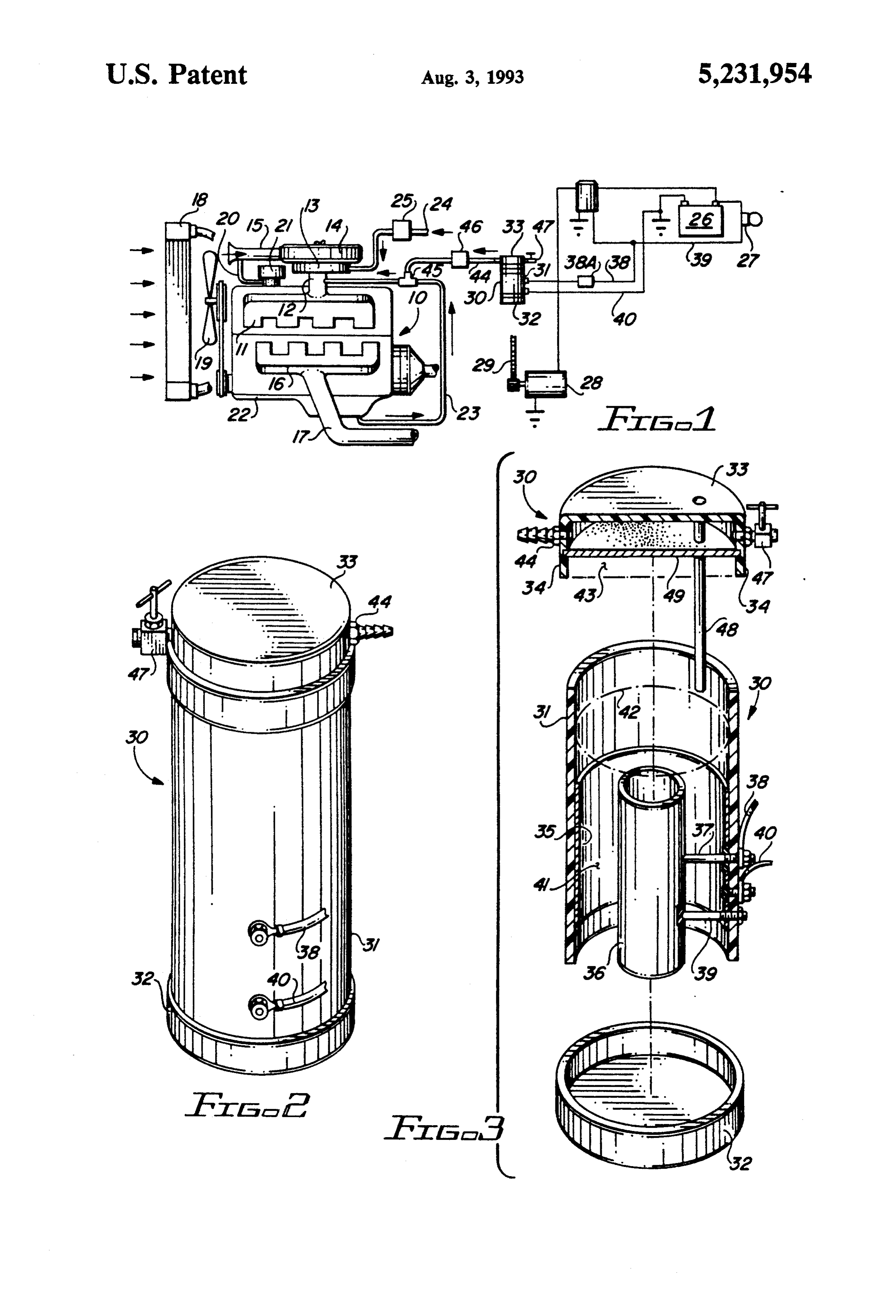
ture, together with the special combination of electro An important feature of the invention is an electroly lyte components to be discussed hereinafter, eliminates sis canister or chamber 30, which is shown in the dia the explosion hazard which hampered past efforts. gram of FIG. 1 and in greater detail in FIGS. 2 and 3. Addition of hydrogen and oxygen to the fuel supply O The chamber 30 illustrated in the drawings is formed as of the engine by use of the present invention enables a a waterproof cylindrical casing 31, made of a chemi substantial improvement in fuel efficiency and mileage cally and electrically inert material, such as high impact per gallon, as well as a striking reduction in noxious plastic, tempered glass, glazed lava, or the like. Cham gases emitting from the engine. ber 30 is not restricted to a cylindrical shape, but may 15 have any suitable configuration, including square, rect
BRIEF DESCRIPTION OF THE DRAWINGS angular, or customfitted, depending upon its location In order that the invention may be better understood, adjacent the engine block 10. As shown in the drawings, a description of the invention is provided herein with casing 31 has a bottom cap 32 which is permanently and reference to the general concepts and an illustrative 20 securely adhered to the casing body, and a top cap 33 which is slip-fitted on the casing 31 and held there by embodiment thereof, wherein:
FIG. 1 is a diagrammatic view of an automobile en friction. To assist in maintaining a seal in the slip-fitting, gine, showing incorporation of the electrolysis device an O-ring seal 34 is built into the side of the top cap. of the present invention. Located within the casing 31 are a cylindrical stain FIG. 2 is a perspective view of the electrolysis device 25 less steel cathode 35, which may be formed as an inner liner for the casing 31, and a cylindrical stainless steel of the invention.
FIG. 3 is an exploded perspective side view of the core anode 36, which is secured concentrically of the cathode cylinder 35. The anode 36 is supported by a electrolysis device, showing top and bottom caps sepa pair of stainless rated from the main body, and indicating the location of to the casing 31.steel Bolt bolts 37 and 39 which are secured 37 is insulated from contact with .
electrodes, gas accumulation zone, gas delivery line, 30 cathode 35 but is electrically connected to anode 36 at and the like. one end and to electrical wire 38 at the other end. Wire DESCRIPTION OF THE PREFERRED 38 runs through a fuse box 38A and then connects with EMBODEMENT wire 39, which leads through ignition key switch 27 and connects with the positive pole of battery 26. Bolt 39 is
Referring now to the drawings, wherein like refer 35 insulated from electrical contact with both cathode 35 ence characters denote corresponding elements and anode 36, and acts merely as a second support men throughout the several views, and first to FIG. 1, an ber for holding anode 36 in place. A second wire 40 is in internal combustion engine of the piston type in which electrical contact with cathode 35 and leads to the nega fuel is ignited by spark plugs is shown as including an tive ground pole of the battery 26, or vehicle frame, if engine block represented at 10. Mounted on engine grounded.
block 10 is a fuel intake manifold 11 having a main stem As shown in FIG. 3, the electrolysis chamber con 12 on which is mounted a carburetor 13 for hydrocar tains an aqueous electrolyte solution 41, which is nor bon fuel such as gasoline. Mounted above carburetor 13 mally filled to a level 42 above the top of cathode 35 and is an air filter 14 having an air intake 15. anode 36. When current is applied and passes through Carried by engine block 10 is an exhaust manifold 16 45 the electrolyte solution between the electrodes 35 and from which extends an exhaust pipe 17. Engine block10 36, the water in the solution is decomposed to produce includes a cooling system in accordance with accepted hydrogen and oxygen gas, which rises upwardly above practice and hence is not illustrated here. However, a the electrolyte level 42 and collects in a gas accumula radiator and a fan which may be considered as part of a tion zone 43. Hydrogen and oxygen which reach the cooling system are illustrated at 18 and 19 respectively. 50 gas accumulation zone are instantly drawn off through The engine includes a positive crankcase ventilation a gas outlet line 44, connected to an opening in top cap (PCV) system, in which a source of air is drawn from 33. The line 44 is connected at the other end to the the air intake 15 through a tube 20 into the oil filler cap crankcase vacuum hose 23 of the engine, through a assembly 21, from where the air flows past rocker arms Tjoint 45, and accordingly the hydrogen and oxygen and pushrods (not shown) into the crankcase 22. The air 55 gases generated in the electrolysis chamber 30 are con and accumulated crankcase gases then enter a spring ducted into the main stem 12 and into the intake mani loaded regulator valve (PCV valve, not shown), from fold 11 of the engine. A backflash arrestor valve 46 is where the air and gas mixture is routed from the crank located in line 44 to prevent accidental explosion of case 22 through a crankcase vent hose tube 23 to the hydrogen and oxygen gases in the event of engine back main stem 12 of the intake manifold 11, from where the fire.
crankcase gases may be burned with the incoming fuel The top ca 33 of the electrolysis chamber 30 is fitted and air mixture. The crankcase vent hose tube 23 is a with an intake air adjustment valve 47, which permits vacuum tube and creates a negative pressure on the emission control mechanics to mix air with the accumu system continuously while the engine is running. lated hydrogen and oxygen gases in such proportions as The engine includes an associated fuel tank (not 65 may be needed to conform to existing emission control shown) from which gasoline or other fuel is drawn regulations, as applied to the particular type and size of through line 24 by fuel pump 25 and introduced into the engine. An optional air cooling tube 48 extends from the carburetor 13. top cap 33 and terminates at a point below the surface
Page 5
42 of the aqueous electrolyte solution 41, allowing, if is actuated by turning the ignition switch key to start desired, an additional supply of air to be drawn into the the engine. Hydrogen and oxygen are generated as long solution and to assist in liberation of hydrogen and oxy as the engine is running. When the key is turned to the gen gas bubbles from the electrodes. The top cap 33 is off position, the motor stops, and so does the generating also fitted with a thick fiber splash guard membrane 49 of hydrogen and oxygen gases.
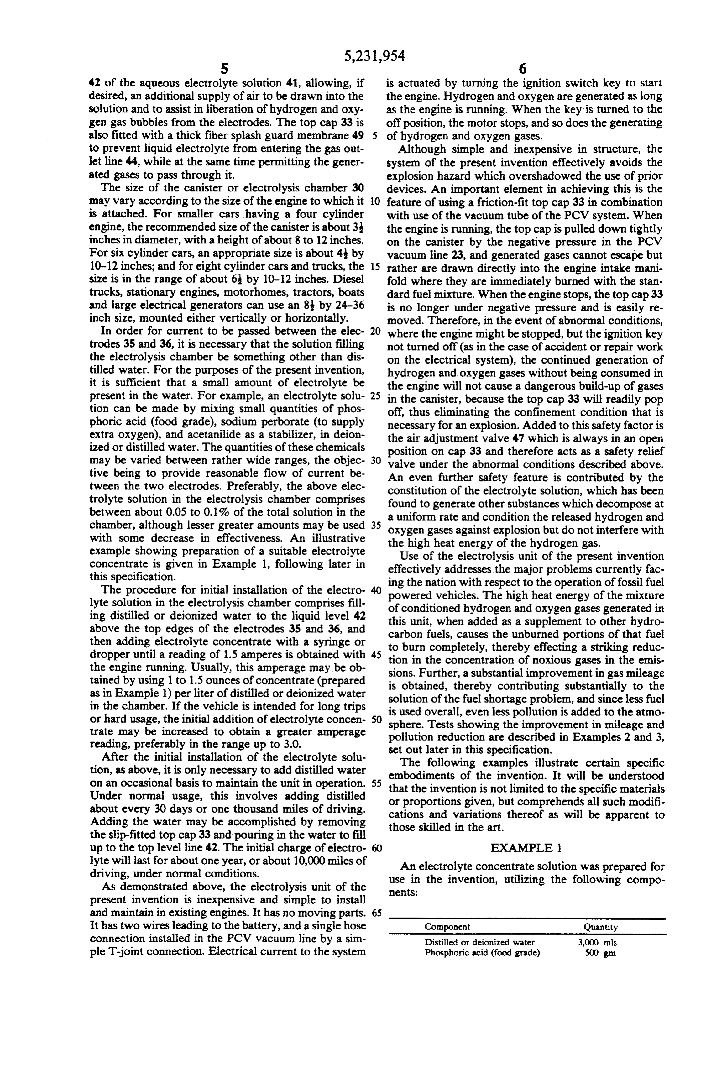
to prevent liquid electrolyte from entering the gas out Although simple and inexpensive in structure, the let line 44, while at the same time permitting the gener system of the present invention effectively avoids the ated gases to pass through it. explosion hazard which overshadowed the use of prior The size of the canister or electrolysis chamber 30 devices. An important element in achieving this is the may vary according to the size of the engine to which it 10 feature of using a friction-fit top cap 33 in combination is attached. For smaller cars having a four cylinder with use of the vacuum tube of the PCV system. When engine, the recommended size of the canister is about 3. the engine is running, the top cap is pulled down tightly inches in diameter, with a height of about 8 to 12 inches. on the canister by the negative pressure in the PCV For six cylinder cars, an appropriate size is about 4 by vacuum line 23, and generated gases cannot escape but 10-12 inches; and for eight cylinder cars and trucks, the 15 rather are drawn directly into the engine intake mani size is in the range of about 6 by 10-12 inches. Diesel fold where they are immediately burned with the stan trucks, stationary engines, motorhomes, tractors, boats dard fuel mixture. When the engine stops, the top cap 33 and large electrical generators can use an 8 by 24-36 is no longer under negative pressure and is easily re inch size, mounted either vertically or horizontally. moved. Therefore, in the event of abnormal conditions, In order for current to be passed between the elec 20 where the engine might be stopped, but the ignition key trodes 35 and 36, it is necessary that the solution filling not turned off (as in the case of accident or repair work the electrolysis chamber be something other than dis on the electrical system), the continued generation of tilled water. For the purposes of the present invention, hydrogen and oxygen gases without being consumed in it is sufficient that a small amount of electrolyte be the engine will not cause a dangerous build-up of gases present in the water. For example, an electrolyte solu 25 in the canister, because the top cap 33 will readily pop tion can be made by mixing small quantities of phos off, thus eliminating the confinement condition that is phoric acid (food grade), sodium perborate (to supply necessary for an explosion. Added to this safety factor is extra oxygen), and acetanilide as a stabilizer, in deion the air adjustment valve 47 which is always in an open ized or distilled water. The quantities of these chemicals position on cap 33 and therefore acts as a safety relief may be varied between rather wide ranges, the objec 30 valve under the abnormal conditions described above. tive being to provide reasonable flow of current be An even further safety feature is contributed by the tween the two electrodes. Preferably, the above elec constitution of the electrolyte solution, which has been trolyte solution in the electrolysis chamber comprises found to generate other substances which decompose at between about 0.05 to 0.1% of the total solution in the a uniform rate and condition the released hydrogen and chamber, although lesser greater amounts may be used 35 oxygen gases against explosion but do not interfere with with some decrease in effectiveness. An illustrative the high heat energy of the hydrogen gas. example showing preparation of a suitable electrolyte Use of the electrolysis unit of the present invention concentrate is given in Example 1, following later in effectively addresses the major problems currently fac this specification.
The procedure for initial installation of the electro powered vehicles. The high heat operation ing the nation with respect to the energy of of fossil fuel the mixture lyte solution in the electrolysis chamber comprises fill of conditioned hydrogen and oxygen gases generated in ing distilled or deionized water to the liquid level 42 this unit, when added as a supplement to other hydro above the top edges of the electrodes 35 and 36, and carbon fuels, causes the unburned portions of that fuel then adding electrolyte concentrate with a syringe or to dropper until a reading of 1.5 amperes is obtained with 45 tionburn in completely, thereby effecting a striking reduc the concentration of noxious gases in the emis the engine running. Usually, this amperage may be ob sions. Further, a substantial improvement in gas mileage tained by using 1 to 1.5 ounces of concentrate (prepared is obtained, thereby contributing substantially to the as in Example 1) per liter of distilled or deionized water solution of the fuel shortage problem, and since less fuel in the chamber. If the vehicle is intended for long trips is used overall, even less pollution is added to the atmo or hard usage, the initial addition of electrolyte concen 50 sphere. Tests showing the improvement in mileage and trate may be increased to obtain a greater amperage pollution reduction are described in Examples 2 and 3, reading, preferably in the range up to 3.0. set out later in this specification. After the initial installation of the electrolyte solu The following examples illustrate certain specific tion, as above, it is only necessary to add distilled water embodiments of the invention. It will be understood on an occasional basis to maintain the unit in operation. that the invention is not limited to the specific materials
Under normal usage, this involves adding distilled about every 30 days or one thousand miles of driving. or proportions given, but comprehends all such modifi cations and variations thereof as will be apparent to
Adding the water may be accomplished by removing the slip-fitted top cap 33 and pouring in the water to fill those skilled in the art.
up to the top level line 42. The initial charge of electro 60 EXAMPLE lyte will last for about one year, or about 10,000 miles of An electrolyte concentrate solution was prepared for driving, under normal conditions.
As demonstrated above, the electrolysis unit of the use nets:
in the invention, utilizing the following compo present invention is inexpensive and simple to install and maintain in existing engines. It has no moving parts. 65
It has two wires leading to the battery, and a single hose Component Quantity connection installed in the PCV vacuum line by a sim Distilled or deionized water 3,000 as ple T-joint connection. Electrical current to the system Phosphoric acid (food grade) 500 gm
Page 6
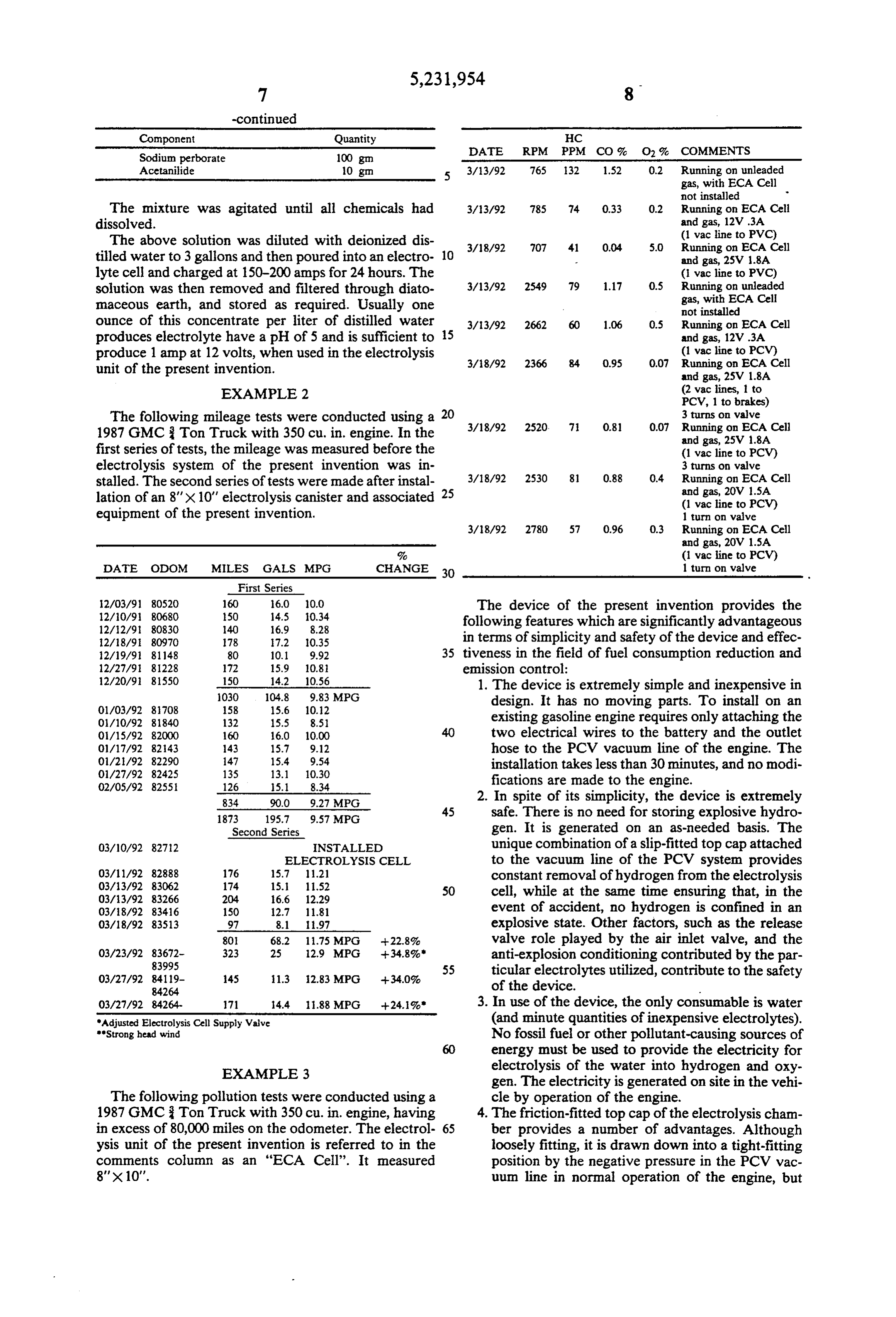
Component Ouantity HC
Sodium perborate 100 gn DATE RPM PPM CO % O % COMMENTS Acetanilide 10 gm 3/13/92 765 132 1.52 02 Running on unleaded gas, with ECA Cell not installed r
The mixture was agitated until all chemicals had 3/3/92 785 74 0.33 0.2 Running on ECA Cell dissolved. E. so wacine to
The above solution was diluted with deionized dis- 3/18/92 707 41 0.04 5.0 Running on ECA Cell tilled water to 3 gallons and then poured into an electro- 10 m and gas, 25W 1.8A lyte cell and charged at 150-200 amps for 24 hours. The (i vac line to PVC) solution was then removed and filtered through diato- 3/13/92 2549 79 1.17 0.5 Running on maceous earth, and stored as required. Usually one AEFA Ce ounce of this concentrate per liter of distilled water 3/13/92 2662 60 1.06 0.5 Running on ECA Cell produces electrolyte have a pH of 5 and is sufficient to 15 and gas, 12V.3A produce 1 amp at 12 volts, when used in the electrolysis (vac line to PCV) unit of the present invention 3/8/92 2366 84 0.95 0.07 Running on ECA Cell p and gas, 25V 1.8A EXA MPLE 2 (2 vac lines, to PCV, 1 to brakes)
The following mileage tests were conducted using a 20 3 turns on valve 1987 GMC Ton Truck with 350 cu. in engine. In the // 220 7 08 00 sing SFCell first series of tests, the mileage was measured before the (vicine to PCV) electrolysis system of the present invention was in- 3 turns on valve stalled. The second series of tests were made after instal- 3/18/92 2530 81 0.88 04 Running SFE,Cell lation of an 8" x 10" electrolysis canister and associated 25 ri to PCV) equipment of the present invention. 1 turn on valve 3/8/92 2780. 57 0.96 0.3 Running on ECA Cell
% (1 vac line to PCV)
DATE ODOM MILES GALS MPG CHANGE 30 1 turn on valve First Series 2/03/91 80520 160 60 00 The device of the present invention provides the 2.92. E. g: following features which are significantly advantageous 2/8/9: 80970 78 ii.2 1035 in terms of simplicity and safety of the device and effec 2A9/9 81148 80 0, 9,92 35 tiveness in the field of fuel consumption reduction and 1227/9 81228 172 15.9 10.8 emission control:
2A20/9 85.50 150 4.2 10.56 1. The device is extremely simple and inexpensive in 01/03/92 8708 1. 1. 8: MPG design. It has no moving parts. To install on an OA10/92 81840 132 15.5 s.si existing gasoline engine requires only attaching the O/15/92 82000 160 160 10.00 40 two electrical wires to the battery and the outlet OM17/92 82.43 43 15.7 9.12 hose to the PCV vacuum line of the engine. The O1/2A92 147 5.4 9.54 installation takes less than 30 minutes, and no modi 877; : E. E. g: fications are made to the engine.
2. In spite of oits simplicity, the y device is a. extremely 1873 195.7 9.57 MPG 45 safe. There is no need for storing explosive hydro Second Series gen. It is generated on an as-needed basis. The
O3/10/92 8272 INSTALLED unique combination of a slip-fitted top Cap attached ELECTROLYSIS CELL to the vacuum line of the PCV system provides
O3/11/92 82888 176 15.7 11.21 constant removal of hydrogen from the electrolysis
50 cell, while at the same time ensuring that, in the
O3/8/92 83416 150 12. 1181 event of accident, no hydrogen is confined in an O3/18/92 83513 97 8.1 1.97 explosive state. Other factors, such as the release 80 68.2 11.75 MPG - 22.8% valve role played by the air inlet valve, and the O3/23/92 83672- 323 25 12.9 MPG -34.8% anti-explosion conditioning contributed by the par
O3/27/92 849- 45 1.3 2.83 MPG - 34.0% ticular f electrolytes utilized, contribute to the safety 84264 of the device.
O3/27/92 84264- 71 14.4 11.88 MPG +24.1% 3. In use of the device, the only consumable is water 'Adjusted Electrolysis Cell Supply Vaive (and minute quantities of inexpensive electrolytes). Strong head wind No fossil fuel or other pollutant-causing sources of 60 energy must be used to provide the electricity for
EXAMPLE 3 electrolysis of the water into hydrogen and oxy gen. The electricity is generated on site in the vehi
The following pollution tests were conducted using a cle by operation of the engine. 1987 GMC 3 Ton Truck with 350 cu. in. engine, having 4. The friction-fitted top cap of the electrolysis cham in excess of 80,000 milies on the odometer. The electrol 65 ber provides a number of advantages. Although ysis unit of the present invention is referred to in the loosely fitting, it is drawn down into a tight-fitting comments column as an "ECA Cell'. It measured position by the negative pressure in the PCV vac 8'x10'. uum line in normal operation of the engine, but
Page 7
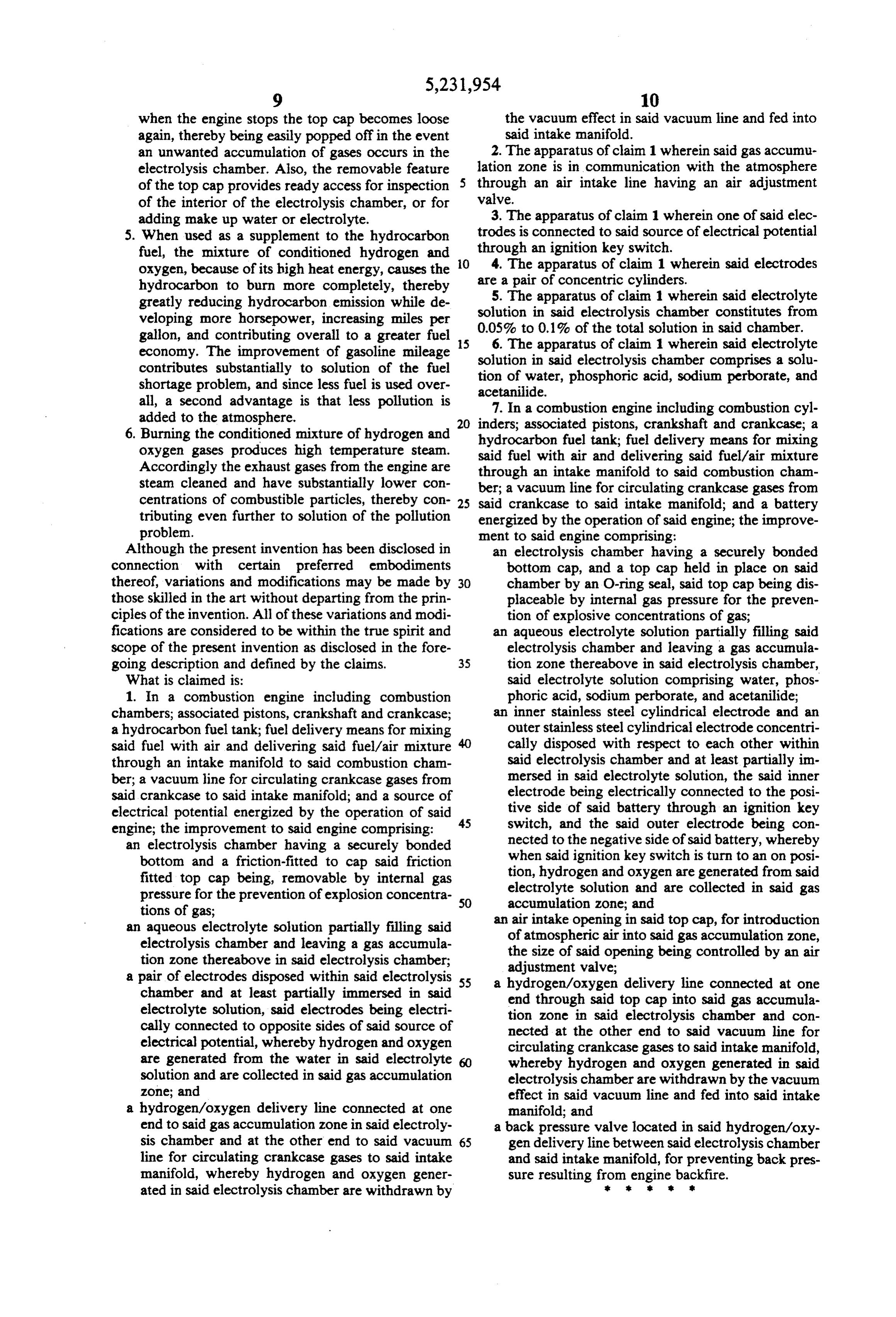
when the engine stops the top cap becomes loose the vacuum effect in said vacuum line and fed into again, thereby being easily popped off in the event said intake manifold.
an unwanted accumulation of gases occurs in the 2. The apparatus of claim 1 wherein said gas accumu electrolysis chamber. Also, the removable feature lation zone is in communication with the atmosphere of the top cap provides ready access for inspection through an air intake line having an air adjustment of the interior of the electrolysis chamber, or for valve.
adding make up water or electrolyte. 3. The apparatus of claim 1 wherein one of said elec 5. When used as a supplement to the hydrocarbon trodes is connected to said source of electrical potential fuel, the mixture of conditioned hydrogen and O through an ignition key switch.
oxygen, because of its high heat energy, causes the 4. The apparatus of claim 1 wherein said electrodes hydrocarbon to burn more completely, thereby are a pair of concentric cylinders.
greatly reducing hydrocarbon emission while de 5. The apparatus of claim 1 wherein said electrolyte veloping more horsepower, increasing miles per solution in said electrolysis chamber constitutes from gallon, and contributing overall to a greater fuel 5 0.05% to 0.1% of the total solution in said chamber. 6. The apparatus of claim 1 wherein said electrolyte economy. The improvement of gasoline mileage solution in said electrolysis chamber comprises a solu contributes substantially to solution of the fuel tion of water, shortage problem, and since less fuel is used over acetanilide. phosphoric acid, sodium perborate, and all, a second advantage is that less pollution is 7. In a combustion engine including combustion cyl added to the atmosphere. 20 inders; associated pistons, crankshaft and crankcase; a 6. Burning the conditioned mixture of hydrogen and hydrocarbon fuel tank; fuel delivery means for mixing oxygen gases produces high temperature steam. said fuel with air and delivering said fuel/air mixture Accordingly the exhaust gases from the engine are through an intake manifold to said combustion cham steam cleaned and have substantially lower con ber; a vacuum line for circulating crankcase gases from centrations of combustible particles, thereby con 25 said crankcase to said intake manifold; and a battery tributing even further to solution of the pollution energized by the operation of said engine; the improve problem. ment to said engine comprising:
Although the present invention has been disclosed in an electrolysis chamber having a securely bonded connection with certain preferred embodiments bottom cap, and a top cap held in place on said thereof, variations and modifications may be made by 30 chamber by an O-ring seal, said top cap being dis those skilled in the art without departing from the prin placeable by internal gas pressure for the preven ciples of the invention. All of these variations and modi tion of explosive concentrations of gas; fications are considered to be within the true spirit and an aqueous electrolyte solution partially filling said scope of the present invention as disclosed in the fore electrolysis chamber and leaving a gas accumula going description and defined by the claims. 35 tion zone thereabove in said electrolysis chamber, What is claimed is: said electrolyte solution comprising water, phos 1. In a combustion engine including combustion phoric acid, sodium perborate, and acetanilide; chambers; associated pistons, crankshaft and crankcase; an inner stainless steel cylindrical electrode and an a hydrocarbon fuel tank; fuel delivery means for mixing outer stainless steel cylindrical electrode concentri said fuel with air and delivering said fuel/air mixture cally disposed with respect to each other within through an intake manifold to said combustion cham said electrolysis chamber and at least partially im ber; a vacuum line for circulating crankcase gases from mersed in said electrolyte solution, the said inner said crankcase to said intake manifold; and a source of electrode being electrically connected to the posi electrical potential energized by the operation of said 45 tive side of said battery through an ignition key engine; the improvement to said engine comprising: switch, and the said outer electrode being con an electrolysis chamber having a securely bonded nected to the negative side of said battery, whereby bottom and a friction-fitted to cap said friction when said ignition key switch is turn to an on posi fitted top cap being, removable by internal gas tion, hydrogen and oxygen are generated from said pressure for the prevention of explosion concentra 50 electrolyte solution and are collected in said gas tions of gas; accumulation zone; and an aqueous electrolyte solution partially filling said an air intake opening in said top cap, for introduction electrolysis chamber and leaving a gas accumula of atmospheric air into said gas accumulation zone, tion zone thereabove in said electrolysis chamber; the size of said opening being controlled by an air a pair of electrodes disposed within said electrolysis 55 adjustment valve;
a hydrogen/oxygen delivery line connected at one chamber and at least partially immersed in said end through said top cap into said gas accumula electrolyte solution, said electrodes being electri tion zone in said electrolysis chamber and con cally connected to opposite sides of said source of nected at the other end to said vacuum line for electrical potential, whereby hydrogen and oxygen circulating crankcase gases to said intake manifold, are generated from the water in said electrolyte 60 whereby hydrogen and oxygen generated in said solution and are collected in said gas accumulation electrolysis chamber are withdrawn by the vacuum zone; and effect in said vacuum line and fed into said intake a hydrogen/oxygen delivery line connected at one manifold; and end to said gas accumulation zone in said electroly a back pressure valve located in said hydrogen/oxy sis chamber and at the other end to said vacuum 65 gen delivery line between said electrolysis chamber line for circulating crankcase gases to said intake and said intake manifold, for preventing back pres manifold, whereby hydrogen and oxygen gener sure resulting from engine backfire. ated in said electrolysis chamber are withdrawn by
Page 8
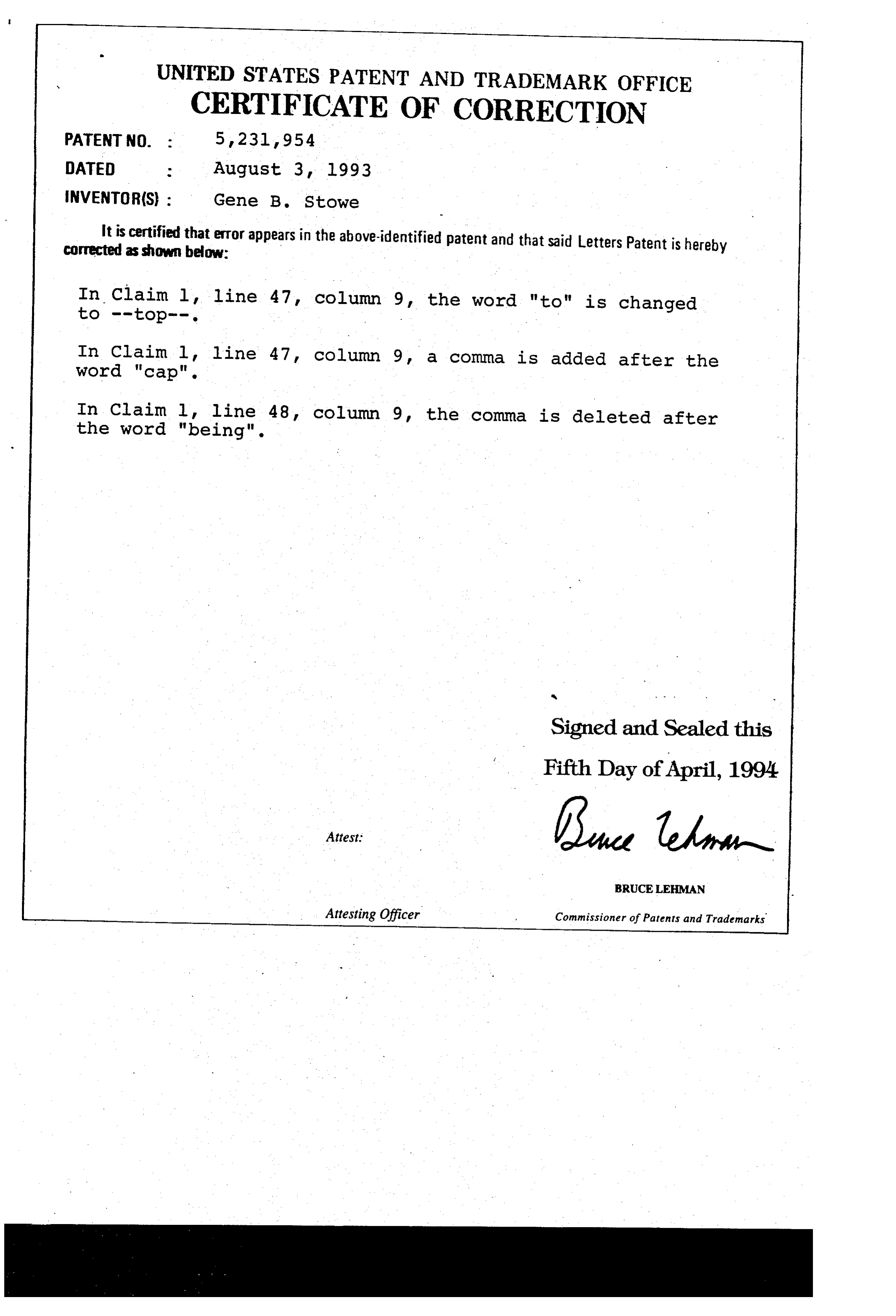
UNITED STATES PATENT AND TRADEMARK OFFICE
PATENT NO. :
CERTIFICATE
OF CORRECTION
INVENTOR(S) : Gene B. Stowe
It isascertified corrected shown that error appears in the above-identified patent and that said Letters Patent is hereby below:
In Claim l, line 47, column 9, the word "to" is changed
In Claim l, line 47 column 9, a comma is added after the word "cap".
In Claim l, line 48, column 9, the comma is deleted after the word "being".
Signed and Sealed this
Fifth Day of April, 1994
BRUCELEHMAN
Attesting Officer Commissioner of Patents and Trademarks
Page 9
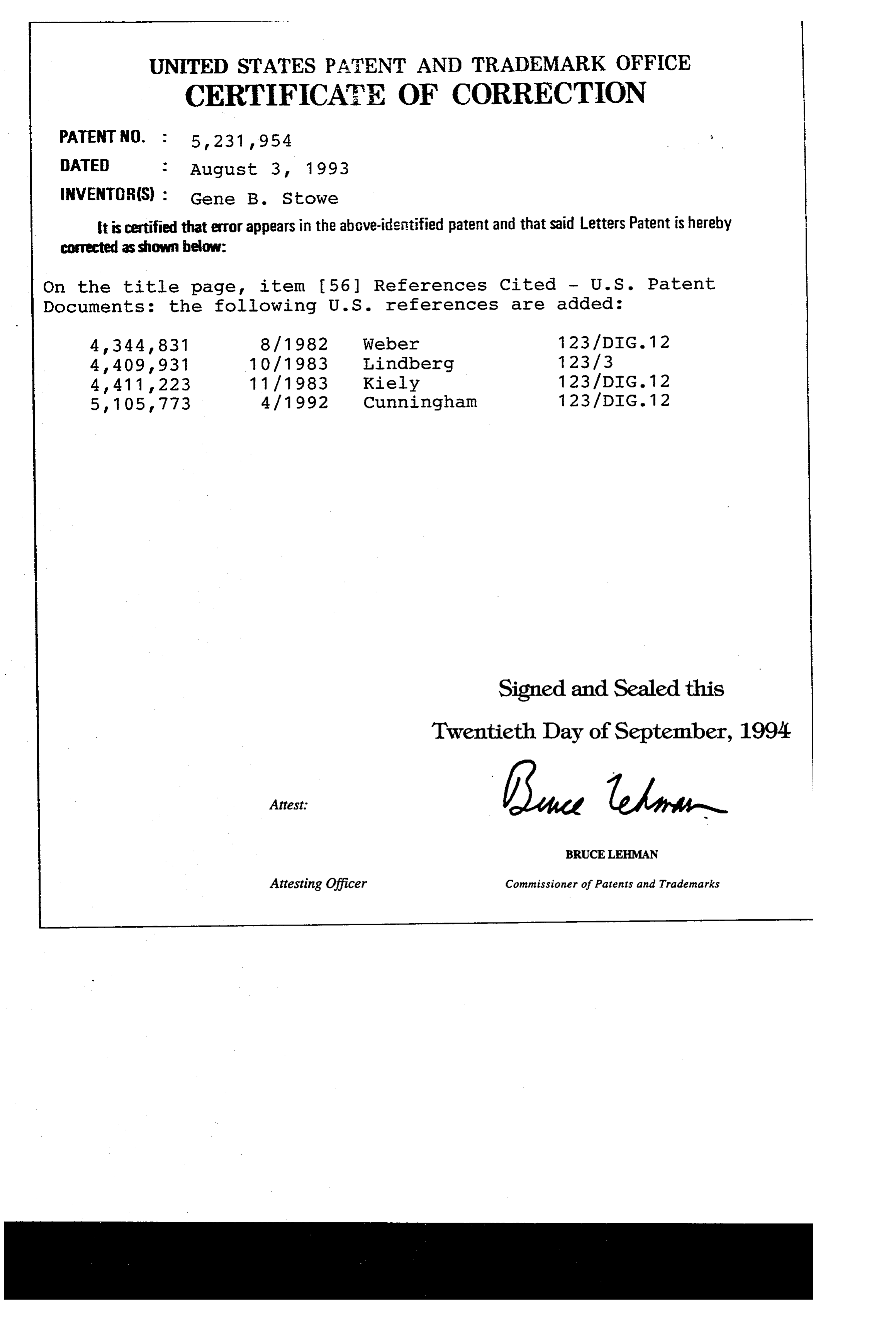
UNITED STATES PATENT AND TRADEMARK OFFICE
CERTIFICATE OF CORRECTION
INVENTOR(S) Gene B. Stowe it is certified that error appears in the above-identified patent and that said Letters Patent is hereby corrected as shown below:
On the title page, item (56) References Cited - U.S. Patent
Documents: the following U.S. references are added:
4, 344, 831 8/1982 Weber 123/DIG. 12 4,409,931 10/1983 Lindberg 123/3 4, 411, 223 11 / 1983 Kiely 123/DIG. 12 5, 105,773 4 / 1992 Cunningham 123/DIG. 12
Signed and Sealed this
Twentieth Day of September, 1994
BRUCELEMAN
Attesting Officer Commissioner of Patents and Trademarks
Provenance
- Collection
- Patents citing this work
- Current assignee
- WATER FUEL INTERNATIONAL Inc, WATER VISIONS Inc
- Pages
- 9
- Method
- pdftotext (the PDF's own text layer) + pdftoppm 300dpi page scans
- Patent office record
- patents.google.com →
- Source
- Google Patents citing-documents table
- Inventors
- Gene B. Stowe
- Published
- 1993-08-03
- Transcribed from
- patentimages.storage.googleapis.com →