patent · US20100064989A1
System and method for use with a combustion engine
18 March 2010
Page 1 — bibliographic record
(19) United States (12) Patent Application Publication (10) Pub. No.: US 2010/0064989 A1
Huttner (43) Pub. Date: Mar. 18, 2010 (54) SYSTEMAND METHOD FOR USE WITH A Publication Classification COMBUSTON ENGINE (51) Int. Cl.
(76) Inventor: Timothy Huttner, Champlin, MN F02D 4I/26 (2006.01) (US) (52) U.S. Cl. ............................................. 123/3; 701/103
RositioSSAGER & TUFTE LLC A system for use with a combustion engine having an air 9 9 intake, sensors and an engine control module, comprising a 1221. NICOLLET AVENUE, SUITE 800 hydrogen cell capable of turning water into hydrogen and MINNEAPOLIS, MN 55403-2420 (US) oxygen gases and a controller electrically connected to the sensors, the engine control module and the hydrogen cell, (21) Appl. No.: 12/561,822 wherein the controller is programmed to rationetrically skew one or more signal inputs to the engine control module to control the engine in response to predetermined signal levels, (22) Filed: Sep. 17, 2009 wherein the controller is programmed to activate the hydro gen cell in response to predetermined signal levels, wherein
Related U.S. Application Data the hydrogen cell is fluidly connected to the engine through the air intake, and wherein the controller is programmed to (60) Provisional application No. 61/097.636, filed on Sep. cause the engine control module to reduce the rate of fuel flow 17, 2008. to the engine and to activate the hydrogen cell simultaneously.
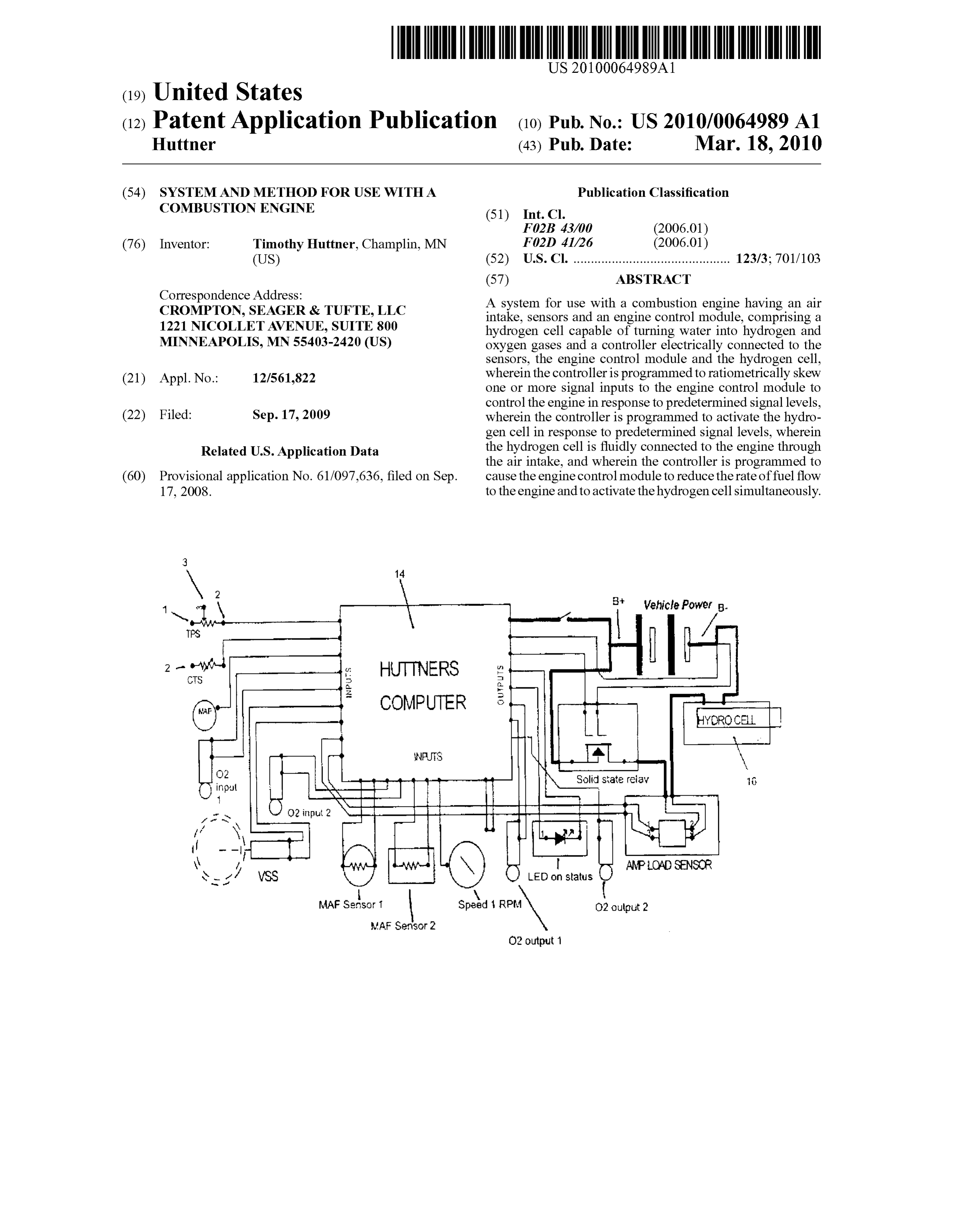
N \ * Vehicle Power B. TPS
COMPUTER
Rhit . N.
Oozinput 2 Nv
PJS
st / WSS O LED on status
MAF SensOr 1 Speed RPM O2 output 2
MAF SeisoF2
O2 output 1
Page 2
Drawing sheet — no readable text.
Page 3
Drawing sheet — no readable text.
Page 4
Drawing sheet — no readable text.
Page 5
Drawing sheet — no readable text.
Page 6
Drawing sheet — no readable text.
Page 7
Drawing sheet — no readable text.
Page 8
Drawing sheet — no readable text.
Page 9
US 2010/0064989 A1 Mar. 18, 2010
SYSTEMAND METHOD FOR USE WITH A to the control module and is also connected to the air intake COMBUSTON ENGINE system where gases produced by the hydrogen cell are intro duced into the engine. The system may have an “off condi tion where the hydrogen cell is inactive and where the com 0001. This application claims the benefit of U.S. Provi puter control module sends the engine system sensor signals sional Ser. No. 61/097,636 filed Sep. 17, 2008. to the engine control module unaltered. In Such a phase, the engine control module runs the engine and associated com
FIELD OF THE INVENTION ponents according to the manufacturer's preset conditions 0002 The invention pertains to a system and method for and programs. The system may also be active. When the altering fuel-based engines such as internal combustion system is active, the system may monitor one or more signal engines for increased fuel efficiency. inputs to the computer control module and alter one or more of the signals sent to the engine control module to thereby
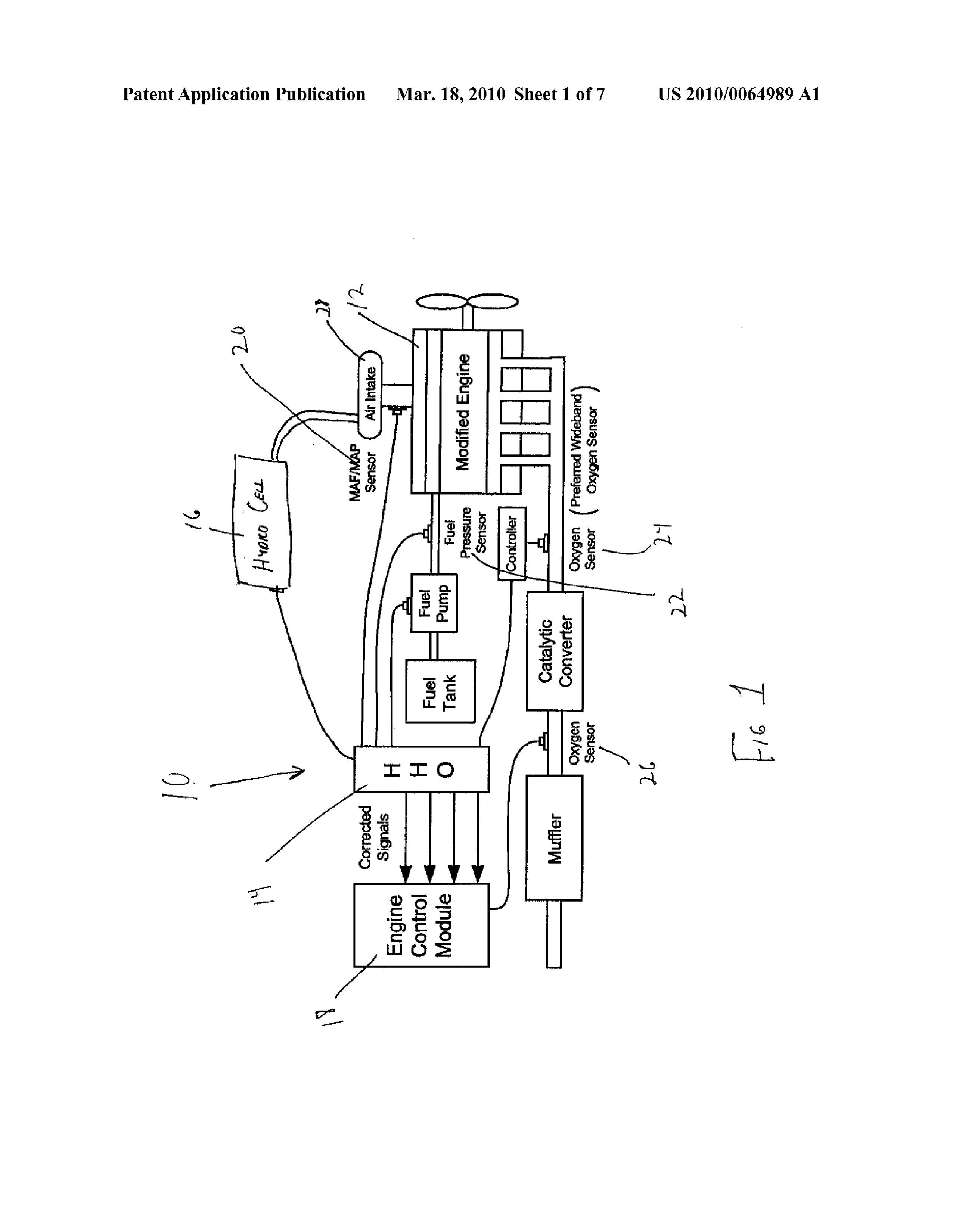
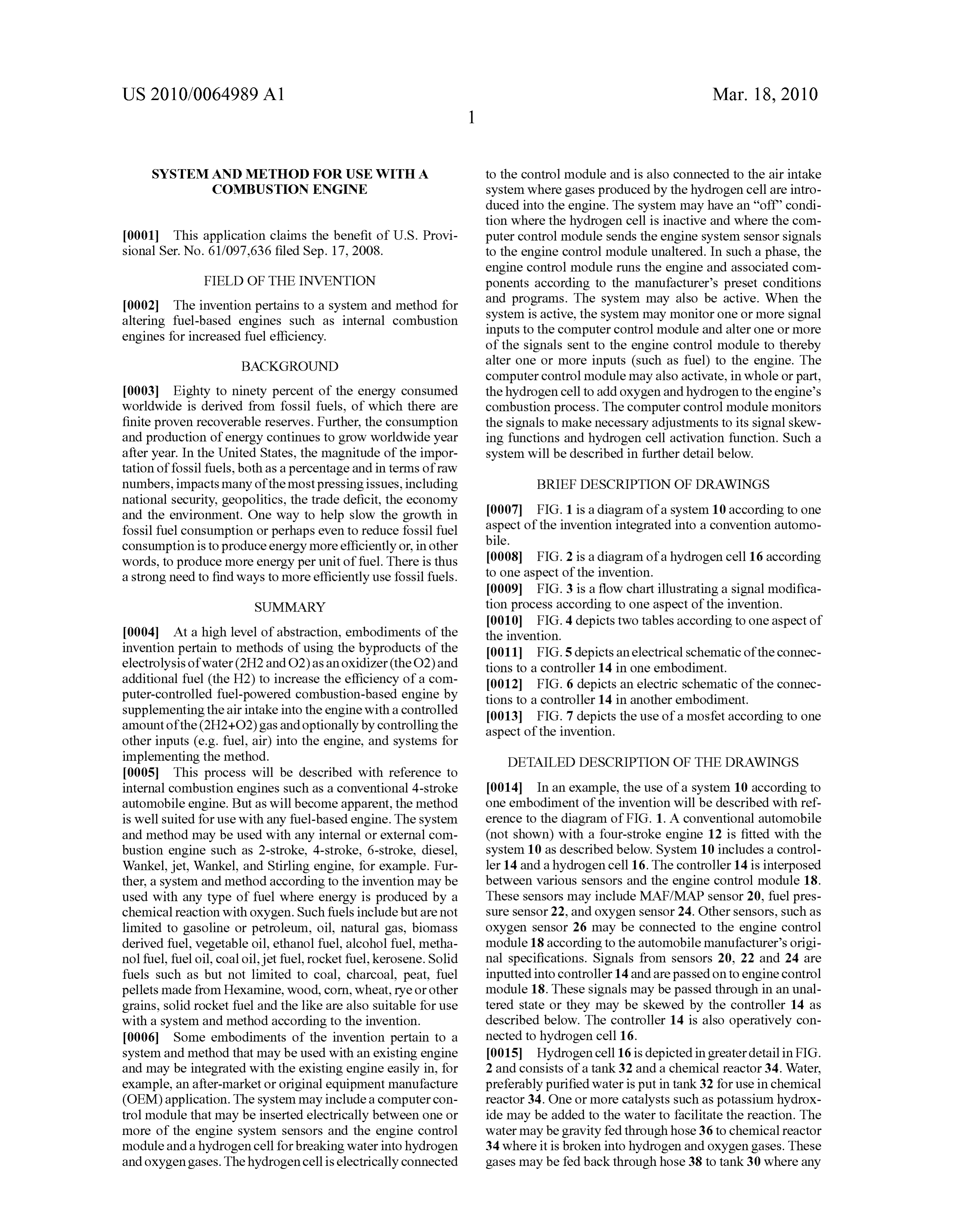
BACKGROUND alter one or more inputs (such as fuel) to the engine. The computer control module may also activate, in whole or part, 0003 Eighty to ninety percent of the energy consumed the hydrogen cell to add oxygen and hydrogen to the engine's worldwide is derived from fossil fuels, of which there are combustion process. The computer control module monitors finite proven recoverable reserves. Further, the consumption the signals to make necessary adjustments to its signal skew and production of energy continues to grow worldwide year ing functions and hydrogen cell activation function. Such a after year. In the United States, the magnitude of the impor system will be described in further detail below. tation of fossil fuels, both as a percentage and in terms of raw numbers, impacts many of the most pressing issues, including BRIEF DESCRIPTION OF DRAWINGS national security, geopolitics, the trade deficit, the economy and the environment. One way to help slow the growth in 0007 FIG. 1 is a diagram of a system 10 according to one fossil fuel consumption or perhaps even to reduce fossil fuel aspect of the invention integrated into a convention automo consumption is to produce energy more efficiently or, in other bile.
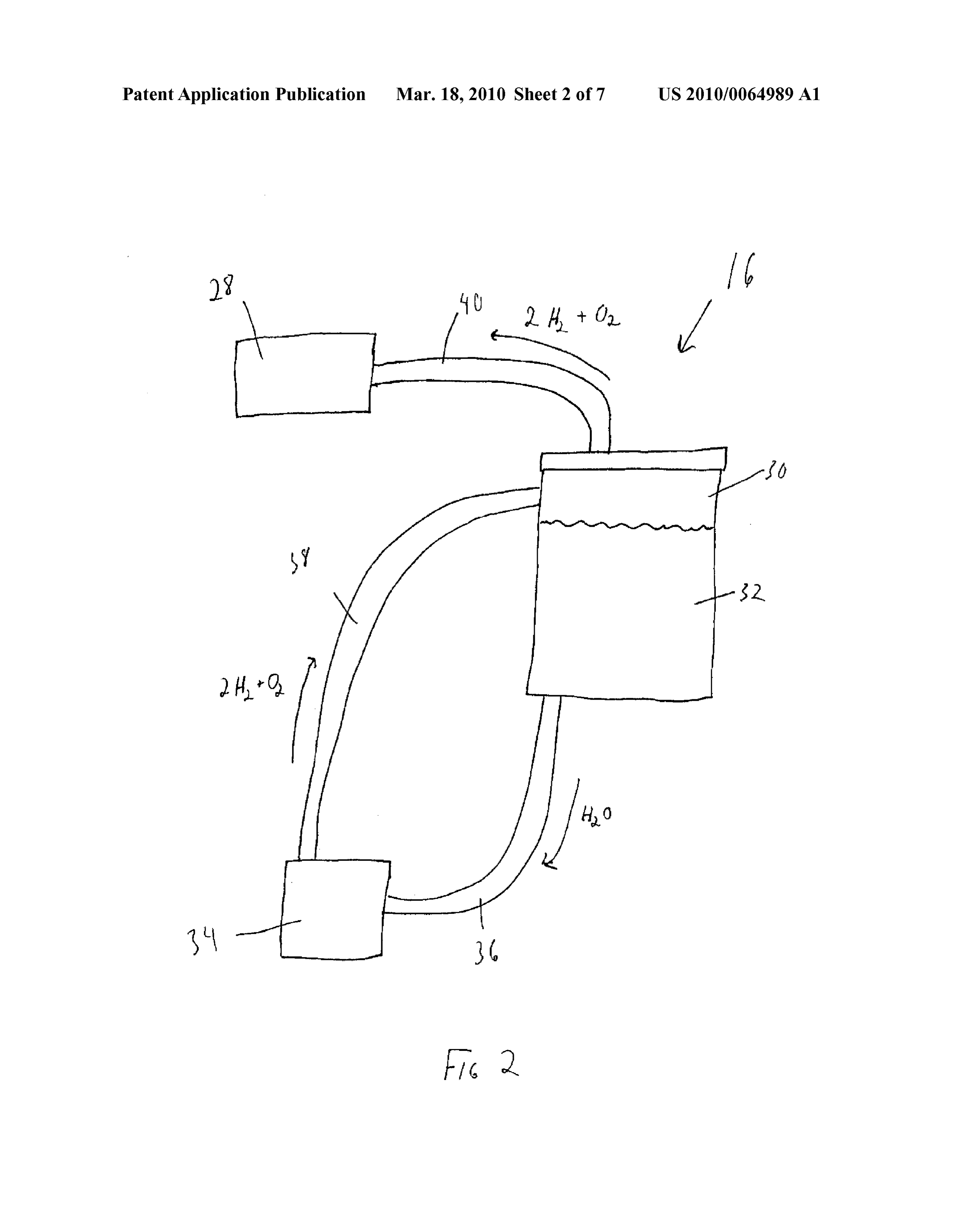
words, to produce more energy per unit of fuel. There is thus 0008 FIG. 2 is a diagram of a hydrogen cell 16 according a strong need to find ways to more efficiently use fossil fuels. to one aspect of the invention.
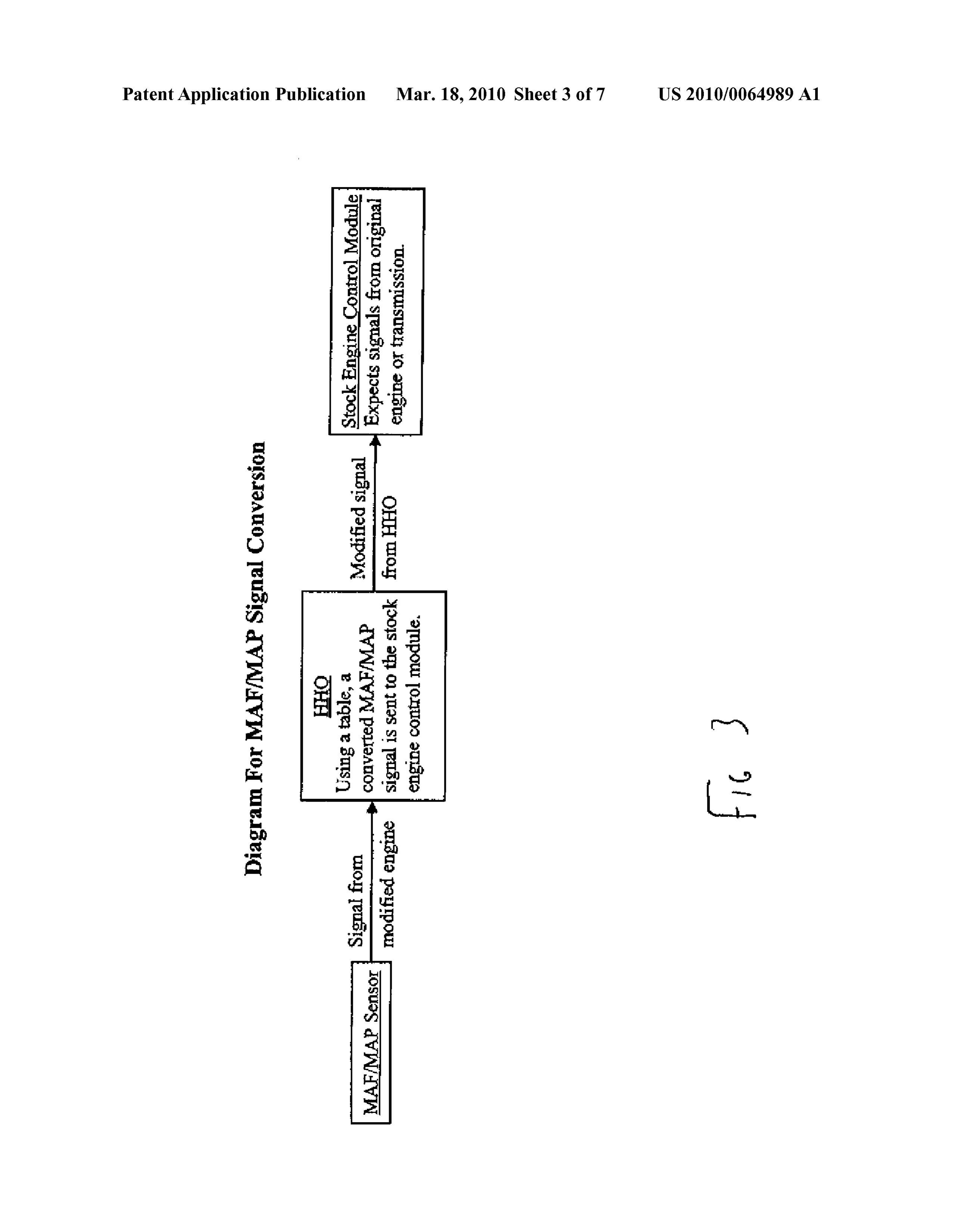
0009 FIG. 3 is a flow chart illustrating a signal modifica
SUMMARY tion process according to one aspect of the invention.
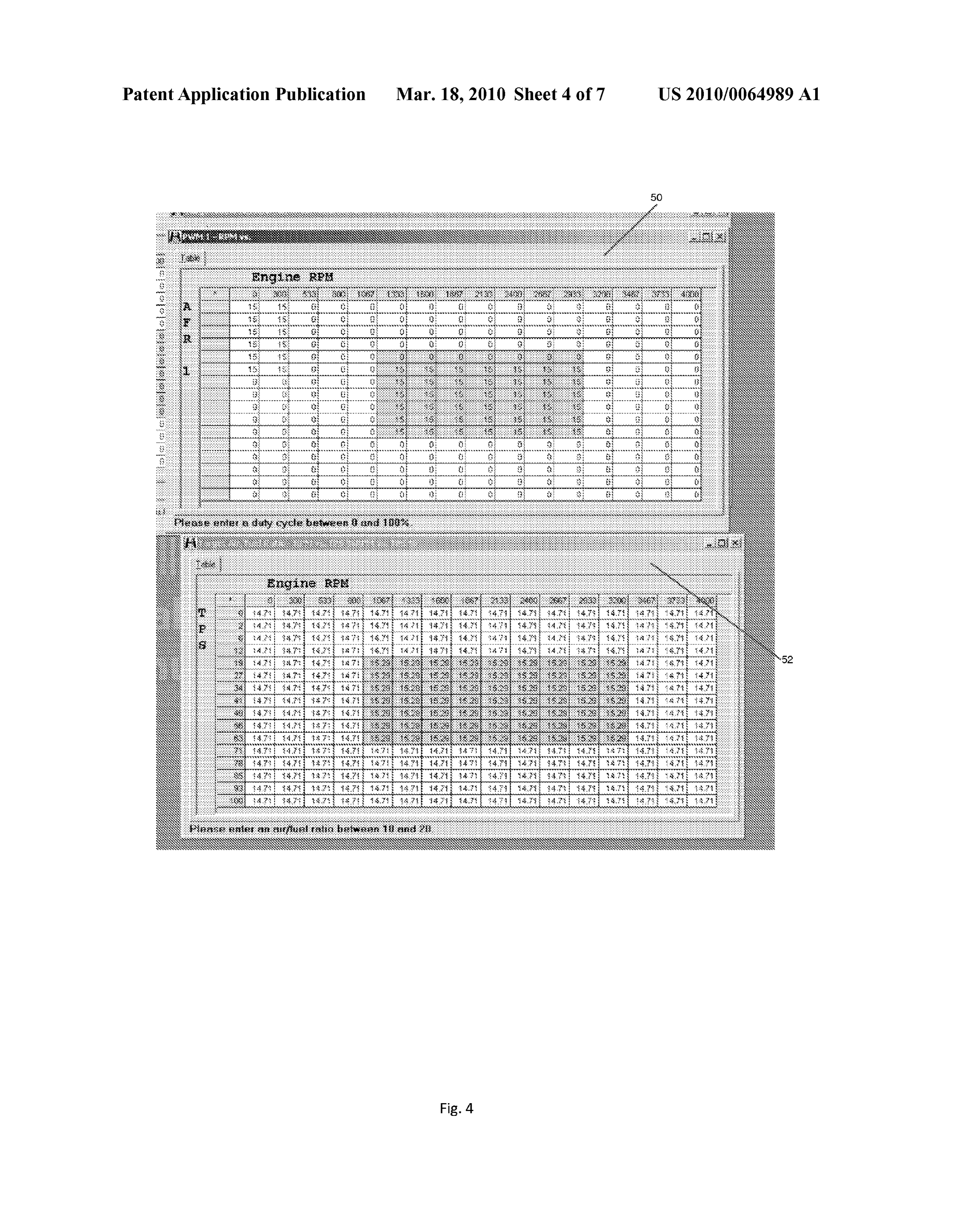
0010 FIG. 4 depicts two tables according to one aspect of 0004 At a high level of abstraction, embodiments of the the invention.
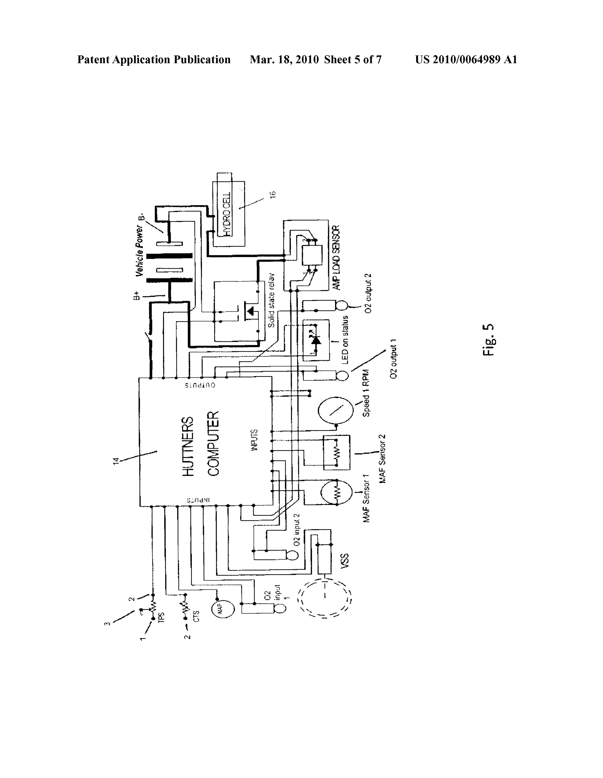
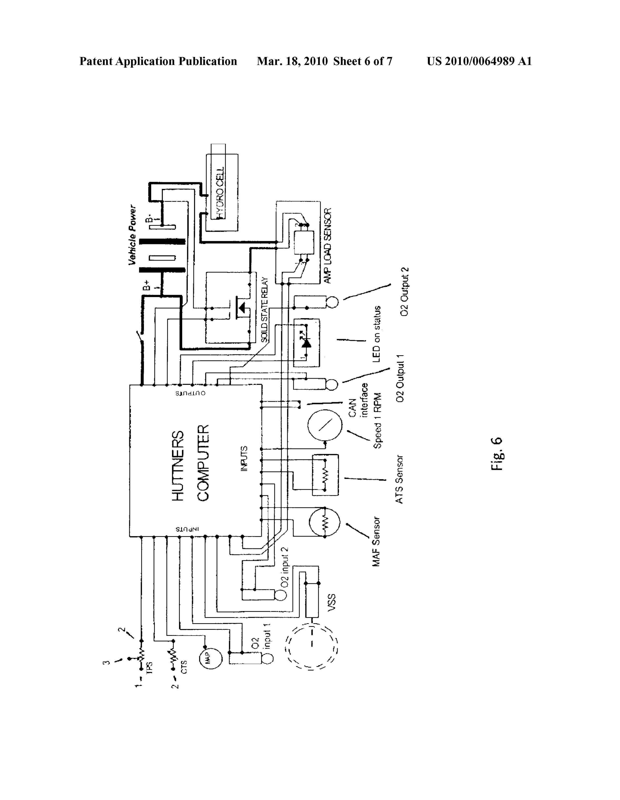
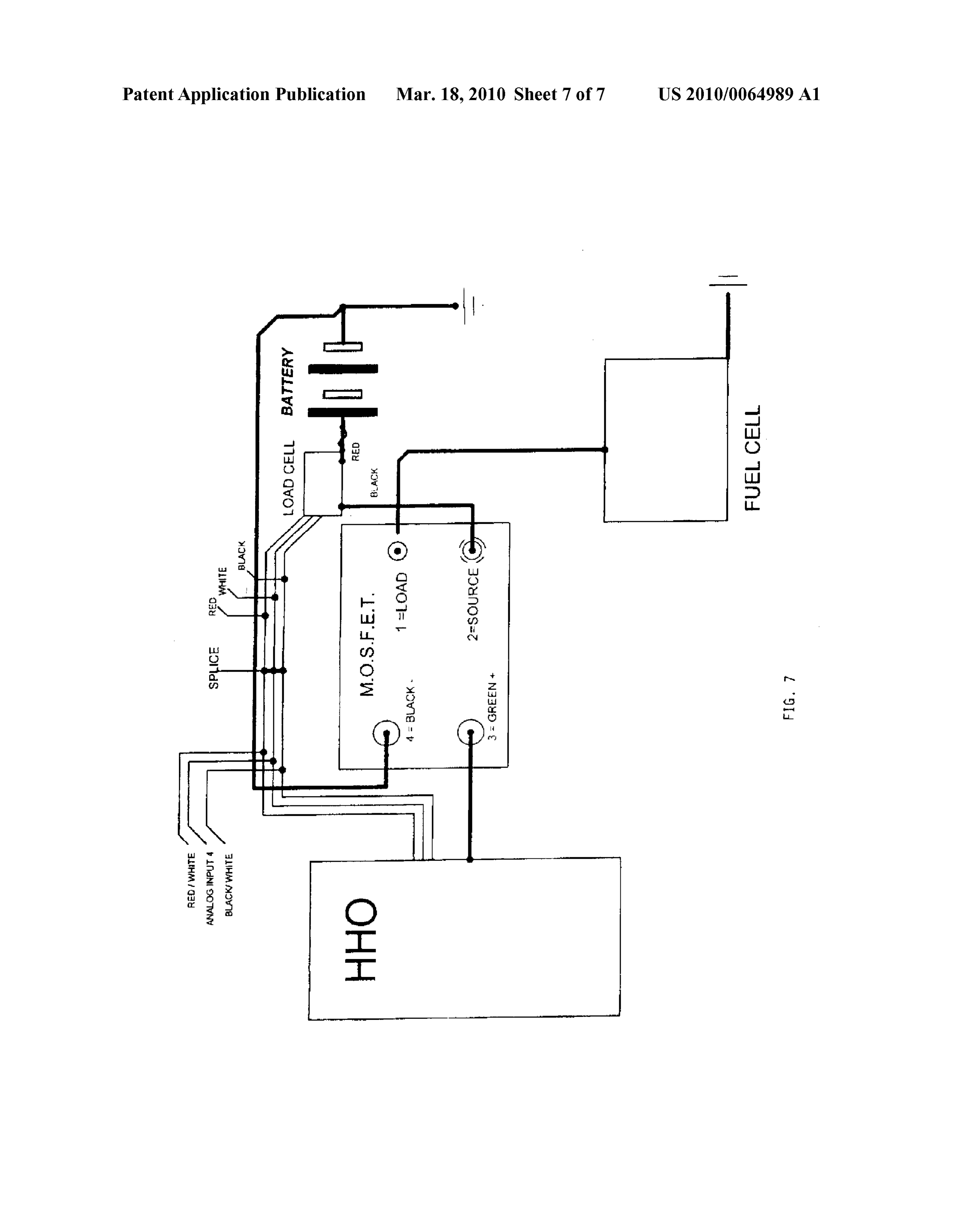
invention pertain to methods of using the byproducts of the 0011 FIG.5 depicts an electrical schematic of the connec electrolysis of water (2H2 and O2) as an oxidizer (the O2) and tions to a controller 14 in one embodiment. additional fuel (the H2) to increase the efficiency of a com 0012 FIG. 6 depicts an electric schematic of the connec puter-controlled fuel-powered combustion-based engine by tions to a controller 14 in another embodiment. Supplementing the air intake into the engine with a controlled 0013 FIG. 7 depicts the use of a mosfet according to one amount of the (2H2+O2) gas and optionally by controlling the aspect of the invention.
other inputs (e.g. fuel, air) into the engine, and systems for implementing the method. DETAILED DESCRIPTION OF THE DRAWINGS 0005. This process will be described with reference to internal combustion engines such as a conventional 4-stroke 0014. In an example, the use of a system 10 according to automobile engine. But as will become apparent, the method one embodiment of the invention will be described with ref is well suited for use with any fuel-based engine. The system erence to the diagram of FIG. 1. A conventional automobile and method may be used with any internal or external com (not shown) with a four-stroke engine 12 is fitted with the bustion engine Such as 2-stroke, 4-stroke, 6-stroke, diesel, system 10 as described below. System 10 includes a control Wankel, jet, Wankel, and Stirling engine, for example. Fur ler 14 and a hydrogen cell 16. The controller 14 is interposed ther, a system and method according to the invention may be between various sensors and the engine control module 18. used with any type of fuel where energy is produced by a These sensors may include MAF/MAP sensor 20, fuel pres chemical reaction with oxygen. Such fuels include but are not Sure sensor 22, and oxygen sensor 24. Other sensors, such as limited to gasoline or petroleum, oil, natural gas, biomass oxygen sensor 26 may be connected to the engine control derived fuel, vegetable oil, ethanol fuel, alcohol fuel, metha module 18 according to the automobile manufacturer's origi nol fuel, fuel oil, coal oil, jet fuel, rocket fuel, kerosene. Solid nal specifications. Signals from sensors 20, 22 and 24 are fuels such as but not limited to coal, charcoal, peat, fuel inputted into controller 14 and are passed on to engine control pellets made from Hexamine, wood, corn, wheat, rye or other module 18. These signals may be passed through in an unal grains, Solid rocket fuel and the like are also Suitable for use tered state or they may be skewed by the controller 14 as with a system and method according to the invention. described below. The controller 14 is also operatively con 0006. Some embodiments of the invention pertain to a nected to hydrogen cell 16.
system and method that may be used with an existing engine 0015 Hydrogen cell 16 is depicted in greater detail in FIG. and may be integrated with the existing engine easily in, for 2 and consists of a tank 32 and a chemical reactor 34. Water, example, an after-market or original equipment manufacture preferably purified water is put in tank 32 for use in chemical (OEM) application. The system may include a computer con reactor 34. One or more catalysts such as potassium hydrox trol module that may be inserted electrically between one or ide may be added to the water to facilitate the reaction. The more of the engine system sensors and the engine control water may be gravity fed through hose 36 to chemical reactor module and a hydrogen cell for breaking water into hydrogen 34 where it is broken into hydrogen and oxygen gases. These and oxygen gases. The hydrogen cell is electrically connected gases may be fed back through hose 38 to tank 30 where any
Page 10
US 2010/0064989 A1 Mar. 18, 2010
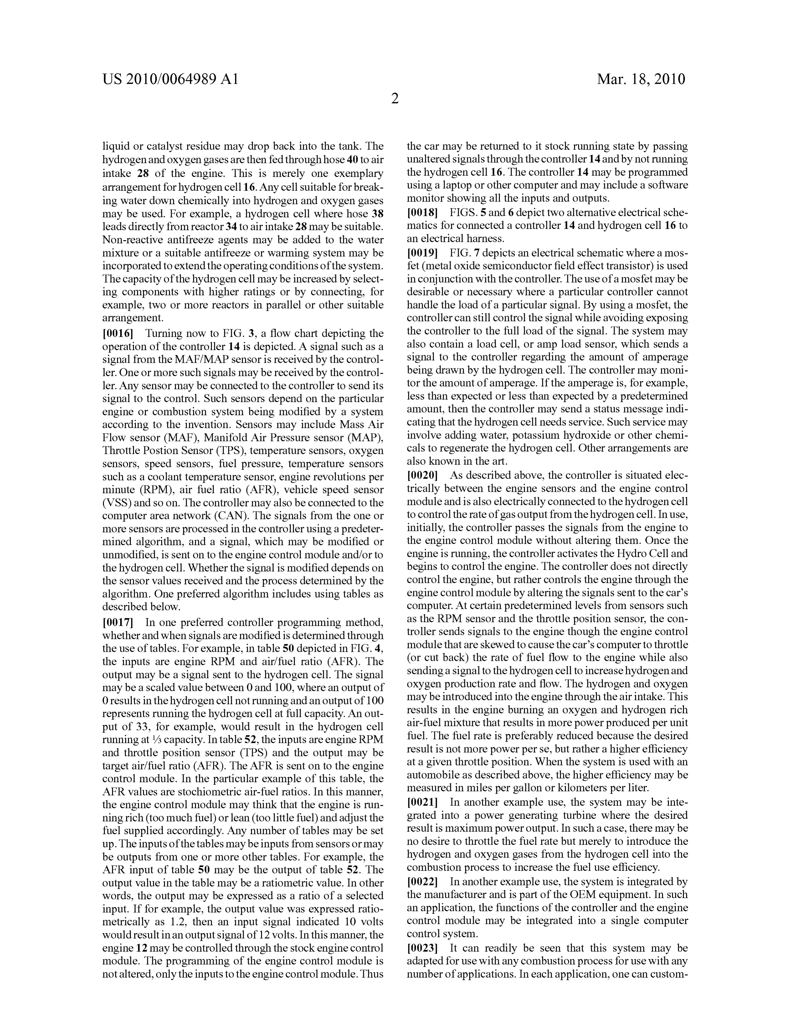
liquid or catalyst residue may drop back into the tank. The the car may be returned to it stock running state by passing hydrogen and oxygen gases are then fed throughhose 40 to air unaltered signals through the controller 14 and by not running intake 28 of the engine. This is merely one exemplary the hydrogen cell 16. The controller 14 may be programmed arrangement for hydrogen cell16. Any cell suitable for break using a laptop or other computer and may include a Software ing water down chemically into hydrogen and oxygen gases monitor showing all the inputs and outputs. may be used. For example, a hydrogen cell where hose 38 (0018 FIGS. 5 and 6 depict two alternative electrical sche leads directly from reactor 34 to air intake 28 may be suitable. matics for connected a controller 14 and hydrogen cell 16 to Non-reactive antifreeze agents may be added to the water an electrical harness.
mixture or a Suitable antifreeze or warming system may be 0019 FIG. 7 depicts an electrical schematic where a mos incorporated to extend the operating conditions of the system. fet (metal oxide semiconductor field effect transistor) is used The capacity of the hydrogen cell may be increased by select in conjunction with the controller. The use of a mosfet may be ing components with higher ratings or by connecting, for desirable or necessary where a particular controller cannot example, two or more reactors in parallel or other suitable handle the load of a particular signal. By using a mosfet, the arrangement. controller can still control the signal while avoiding exposing 0016 Turning now to FIG. 3, a flow chart depicting the the controller to the full load of the signal. The system may operation of the controller 14 is depicted. A signal Such as a also contain a load cell, or amp load sensor, which sends a signal from the MAF/MAP sensor is received by the control signal to the controller regarding the amount of amperage ler. One or more such signals may be received by the control being drawn by the hydrogen cell. The controller may moni ler. Any sensor may be connected to the controller to send its tor the amount of amperage. If the amperage is, for example, signal to the control. Such sensors depend on the particular less than expected or less than expected by a predetermined engine or combustion system being modified by a system amount, then the controller may send a status message indi according to the invention. Sensors may include Mass Air cating that the hydrogen cell needs service. Such service may Flow sensor (MAF), Manifold Air Pressure sensor (MAP), involve adding water, potassium hydroxide or other chemi Throttle Postion Sensor (TPS), temperature sensors, oxygen cals to regenerate the hydrogen cell. Other arrangements are sensors, speed sensors, fuel pressure, temperature sensors also known in the art.
Such as a coolant temperature sensor, engine revolutions per 0020. As described above, the controller is situated elec minute (RPM), air fuel ratio (AFR), vehicle speed sensor trically between the engine sensors and the engine control (VSS) and so on. The controller may also be connected to the module and is also electrically connected to the hydrogen cell computer area network (CAN). The signals from the one or to control the rate of gas output from the hydrogen cell. In use, more sensors are processed in the controller using a predeter initially, the controller passes the signals from the engine to mined algorithm, and a signal, which may be modified or the engine control module without altering them. Once the unmodified, is sent on to the engine control module and/or to engine is running, the controller activates the Hydro Cell and the hydrogen cell. Whether the signal is modified depends on begins to control the engine. The controller does not directly the sensor values received and the process determined by the control the engine, but rather controls the engine through the algorithm. One preferred algorithm includes using tables as engine control module by altering the signals sent to the car's described below. computer. At certain predetermined levels from sensors such 0017. In one preferred controller programming method, as the RPM sensor and the throttle position sensor, the con whether and when signals are modified is determined through troller sends signals to the engine though the engine control the use of tables. For example, in table 50 depicted in FIG. 4, module that are skewed to cause the car's computer to throttle the inputs are engine RPM and air/fuel ratio (AFR). The (or cut back) the rate of fuel flow to the engine while also output may be a signal sent to the hydrogen cell. The signal sending a signal to the hydrogen cell to increase hydrogen and may be a scaled value between 0 and 100, where an output of oxygen production rate and flow. The hydrogen and oxygen 0 results in the hydrogen cell not running and an output of 100 may be introduced into the engine through the air intake. This represents running the hydrogen cell at full capacity. An out results in the engine burning an oxygen and hydrogen rich put of 33, for example, would result in the hydrogen cell air-fuel mixture that results in more power produced per unit running at /3 capacity. In table 52, the inputs are engine RPM fuel. The fuel rate is preferably reduced because the desired and throttle position sensor (TPS) and the output may be result is not more power perse, but rather a higher efficiency target air/fuel ratio (AFR). The AFR is sent on to the engine at a given throttle position. When the system is used with an control module. In the particular example of this table, the automobile as described above, the higher efficiency may be AFR values are stochiometric air-fuel ratios. In this manner, measured in miles per gallon or kilometers per liter. the engine control module may think that the engine is run 0021. In another example use, the system may be inte ning rich (too much fuel) or lean (too little fuel) and adjust the grated into a power generating turbine where the desired fuel Supplied accordingly. Any number of tables may be set result is maximum power output. In Such a case, there may be up. The inputs of the tables may be inputs from sensors or may no desire to throttle the fuel rate but merely to introduce the be outputs from one or more other tables. For example, the hydrogen and oxygen gases from the hydrogen cell into the AFR input of table 50 may be the output of table 52. The combustion process to increase the fuel use efficiency. output value in the table may be a rationetric value. In other 0022. In another example use, the system is integrated by words, the output may be expressed as a ratio of a selected the manufacturer and is part of the OEM equipment. In such input. If for example, the output value was expressed ratio an application, the functions of the controller and the engine metrically as 1.2, then an input signal indicated 10 volts control module may be integrated into a single computer would result in an output signal of 12 volts. In this manner, the control system.
engine 12 may be controlled through the stock engine control 0023. It can readily be seen that this system may be module. The programming of the engine control module is adapted for use with any combustion process for use with any not altered, only the inputs to the engine control module. Thus number of applications. In each application, one can custom
Page 11
US 2010/0064989 A1 Mar. 18, 2010
ize and optimize the system by creating tables having desired 6. The system of claim 1 further comprising an amperage inputs and outputs as described above. The particular inputs load sensor configured to measure the amperage drawn by the and outputs and the optimal output values are dependent on hydrogen cell, wherein the controller is configured to monitor the particular application. the amperage load sensor.
What is claimed is:
1. A system for use with a combustion engine having an air 7. The system of claim 1 comprising a field effect transistor intake, sensors and an engine control module, comprising: electrically integrated Such that the hydrogen cell is con a hydrogen cell capable of turning water into hydrogen and trolled by the controller through the use of the field effect oxygen gases; and transistor.
a controller electrically connected to the sensors, the 8. The system of claim 7 wherein the field effect transistor engine control module and the hydrogen cell, is a metal oxide semiconductor field effect transistor. wherein the controller is programmed to skew one or more 9. A method of increasing the efficiency of a combustion signal inputs to the engine control module to control the engine having an air intake, comprising the steps of: engine in response to predetermined signal levels, wherein the controller is programmed to activate the reducing the rate of flow of a fuel to the engine; and hydrogen cell in response to predetermined signal lev Supplying hydrogen gas and oxygen gas to the engine els, and through the air intake, wherein the hydrogen gas and wherein the hydrogen cell is fluidly connected to the oxygen gas are Supplied in a 2:1 molar ratio. engine through the air 10. The method of claim 9 further comprising the step of intake. electrolyzing water to produce the hydrogen gas and oxygen 2. The system of claim 1 wherein the controller is pro gaS.
grammed to cause the engine control module to reduce the 11. The method of claim 9 wherein the combustion engine rate of fuel flow to the engine and to activate the hydrogen cell is controlled by an engine control module receiving at least simultaneously.
3. The system of claim 1 wherein the controller is pro one signal and wherein the step of reducing the rate of flow is grammed through the use of one or more tables. performed by skewing the at least one signal sent to the engine 4. The system of claim 3 wherein the one or more tables control module.
includes at least 10 rows and 10 columns. 12. The method of claim 11 wherein the signal is skewed 5. The system of claim 1 wherein the controller is config rationetrically.
ured to skew signals rationnetrically.
Provenance
- Collection
- Patents citing this work
- Pages
- 11
- Method
- pdftotext (the PDF's own text layer) + pdftoppm 300dpi page scans
- Patent office record
- patents.google.com →
- Source
- Google Patents citing-documents table
- Assignee
- Timothy Huttner
- Inventors
- Timothy Huttner
- Published
- 2010-03-18
- Transcribed from
- patentimages.storage.googleapis.com →