patent · US4339324
Polycell gas generator
13 July 1982
Page 1 — bibliographic record
United States Patent (19) 11 4,339,324 Haas 45) Jul. 13, 1982 54). POLYCELL GAS GENERATOR : 2/1975 Lindstrom ........................... 32:
(75) Inventor: Richard M. Haas, Phoenix, Ariz. 3,990,962 11/1976 g- - ... 204/268 73) Assignee: Henes Products Corp., Phoenix, Ariz. 3,994,798 11/1976
(21) Appl. No.: 212,274 4,124,478 11/1978 Tsien et al. ..... ... 204/255 w 4,124,480 11/1978 Stevenson. ... 204/268 22 Filed: Dec. 3, 1980 4,196,069 4/1980 Mose et al. . 204/257 (5) Int. Cli.............................................. C25B 9/00 4,206,029 6/1980 Spirig ........ ... 204/228 52) U.S.C. .................................... 204/270; 204/257; FOREIGN PATENT DOCUMENTS
58) Field of Search ................................ 204/254-258, 864245. 4/1941 France ................................ 204/255 204/267-269, 129, 270 Primary Examiner-R. L. Andrews (56) References Cited Attorney, Agent, or Firm-Warren F. B. Lindsley
l,660,147 2/1928 Allan ................................... 204/256 An improved gas generator comprising a multiplicity of 3,291,714 12/1966 Hall et al. ...... 204/256 electrolytic cells arranged to accommodate a series 3,316,167.4/1967 Clarke et al... 20/20 current path, parallel electrolytic flow and minimized 3,451,906 6/1969 Weed ............. a sess 204/82 - 204/268 leakage current paths, in a stacked plate configuration
E. 8. Sother 204/229 that affords a high degree of portability at low cost. 3,692,661 9/1972 Shockcor ............................ 204/269 3,824,172 7/1974 Hodges ............................... 204/269 10 Claims, 21 Drawing Figures
Page 2
Drawing sheet — no readable text.
Page 3
Drawing sheet — no readable text.
Page 4
Drawing sheet — no readable text.
Page 5
Drawing sheet — no readable text.
Page 6
Drawing sheet — no readable text.
Page 7
requirements at higher voltages resulting in higher elec
POLYCELL GAS GENERATOR trical efficiency because of the reduced rectifier losses.
BACKGROUND OF THE INVENTION disclosed employ several cells arranged in parallel This invention relates to electrolysis and more partic 5 lyte.
rather than in series relative to the flow of the electro
Thus, all the cells are operated at the same hydrau ularly to the electrolysis of water for the generation of lic pressure. This arrangement promotes rapid electro hydrogen and oxygen, the combination of which is lyte circulation which is desirable for cooling as well as commonly referred to as detonating gas.
Electrolysis is a process in which an electric current 10 for sweeping out the generated gas, thereby maintaining maximum contact between the electrolyte and the elec is passed through a liquid causing a chemical reaction to trode surfaces. Low operating temperatures and high take place. If the liquid is water, electrolysis "breaks gas generation rates are thus achieved. up' the water into two gases, namely hydrogen and It will be noted that the apparatus described in U.S. oxygen. In the electrolysis of water, the hydrogen gas Pat. No. 4,014,777 embodies both of the desirable fea collects at the cathode electrode and the oxygen gas 15 tures listed thus far, i.e., series electric current flow collects at the anode electrode of the gas generator. through the cells and parallel electrolyte flow across its : Because pure water is not a suitable conductor of elec plates. In the structure of U.S. Pat. No. 4,014,777, how tricity, a salt such as potassium hydroxide is added to ever, the openings forming the electrolyte inlet and the water to form an electrically conductive solution. outlet ports introduce a shunt or leakage current path Such a solution is known as an electrolyte. This process 20 between adjacent cells which, by virtue of their series generates gas as a function of the surface area of the electrical arrangement, are at different electric poten anode and cathode electrodes in contact with the elec tials. These leakage currents account for electrical trolyte and directly proportional to the amount of cur losses which reduce the overall efficiency of the appara rent flowing through the gas generator. tus. This same deficiency is to be noted to some extent One important practical use of the detonating gas 25 in the other serially energized devices disclosed in U.S. produced by this means is as a fuel for welding equip Pat. Nos. 3,518, 180; 3,957,618; 3,990,962; 3,994,798 and ment. In this type of application, the proportions of 4,124,480. To minimize such leakage currents and their oxygen and hydrogen produced by electrolysis (one associated losses, the inlet and outlet ports should be part oxygen is two parts hydrogen) exactly matches the designed or arranged in a manner such that the ratio of proportions needed for recombination (combustion) in 30 the length of the path through each port to the cross the flame of an associated welding torch. sectional dimension of the same path is considerably greater than unity. The inlet and outlet tubes provided
DESCRIPTION OF THE PRIOR ART in the device disclosed in U.S. Pat. No. 3,451,906 tend Present day apparatus in use for generating detonat to reduce such losses but fail to accomplish the results ing gas are generally very bulky and inefficient devices. 35 claimed hereini, including portability and low cost, par Because of their poor operating characteristics, they ticularly for applications such as welding, respirators, etc. Further, none of the modifications disclosed herein have not been ideally suited for use in mobile or porta separates ble equipment. - the hydrogen and oxygen gases as they are Although many patents have issued over the years 40 generated.
directed to electrolysis equipment, none have devel oped an efficient compact polycell configuration dis SUMMARY OF THE INVENTION closed and claimed herein. - In accordance with the invention claimed, a highly efficient gas generator is provided utilizing a novel cell
U.S. Pat. No. 3,616,436 discloses a single pair of configuration anode and cathode electrodes in a single electrolytic 45 path through itsthat provides a series electrical current several cells in combination with paral cell for the production of oxygen. . lel electrolyte paths through the cells. The assembly is U.S. Pat. No. 3,451,906 discloses a multi-cell appara characterized by low cost, portability and minimum tus for the production of halates, perhalates or hypoha leakage currents.
lates of alkali metals.
U.S. Pat. No. 3,518,180 describes a bipolar electro It is, therefore, one object of the present invention to lytic cell and an assembly comprising a multiplicity of 50 provide a new and improved electrolytic gas generator. Another object of this invention is to provide an such rates.
cells for use in producing chlorates and perchlo efficient gas generator for producing hydrogen and oxygen gases.
U.S. Pat. No. 3,692,661 describes an apparatus for A further object of the invention is to provide an removing pollutants and ions from liquids. 55 improved and efficient gas generator employing the U.S. Pat. No. 3,824,172 describes an electrolytic cell series flow of electrical current in combination with for the production of alkali metal chlorates. parallel electrolyte flow through the several cells of the U.S. Pat. Nos. 3,957,618; 3,990,962; 4,014,777 and generating device in a compact, novel and efficient 4,206,029 describe further apparatus for the generation polycell gas generator.
of detonating gas. " . 60 A still further object of this invention is to enhance U.S. Pat. No. 3,994,798 describes an electrode assem the operating efficiency of gas generators by the use of bly for use in multi-cell electrolysis apparatus. a physical arrangement of parts in which the electrolyte U.S. Pat. No. 4,124,480 describes a bipolar cell for use flow is unidirectional in a straight line and orthogonal primarily in the manufacture of sodium hypochlorite. with respect to electric, current flow through the cell. In U.S. Pat. Nos. 3,451,906; 3,518, 180; 3,957,618; 65 A still further object of this invention is to implement 3,990,962; 4,014,777; 3,994,798 and 4,124,480, the indi such simultaneous series electrical current flow and vidual cells are serially energized by an electric current. parallel electrolyte flow in conjunction with a novel This is desirable because it results in reduced current arrangement of the inlet and outlet electrolyte ports
Page 8
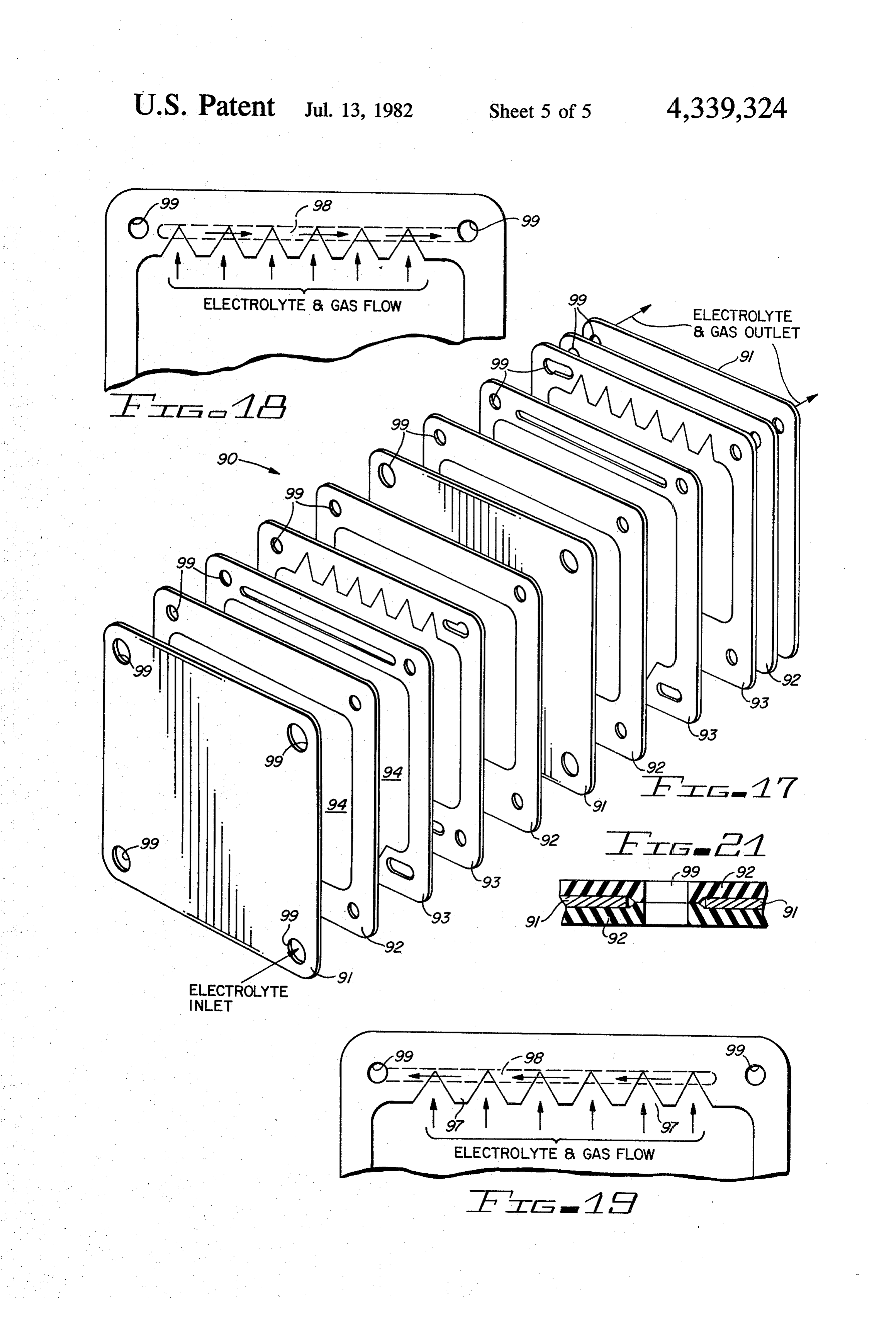
which effectively reduces leakage currents and the FIG. 18 is a partial plan view of a pair of separator associated electrical losses. frames on one side of the electrode, one turned 180 A still further object of this invention is to provide an degrees from the other forming adjacent parts of the improved gas generator which separates and discharges assembly shown in FIG. 1 and showing the electrolyte separately the generated hydrogen and the oxygen 5 and gas flow in one direction;
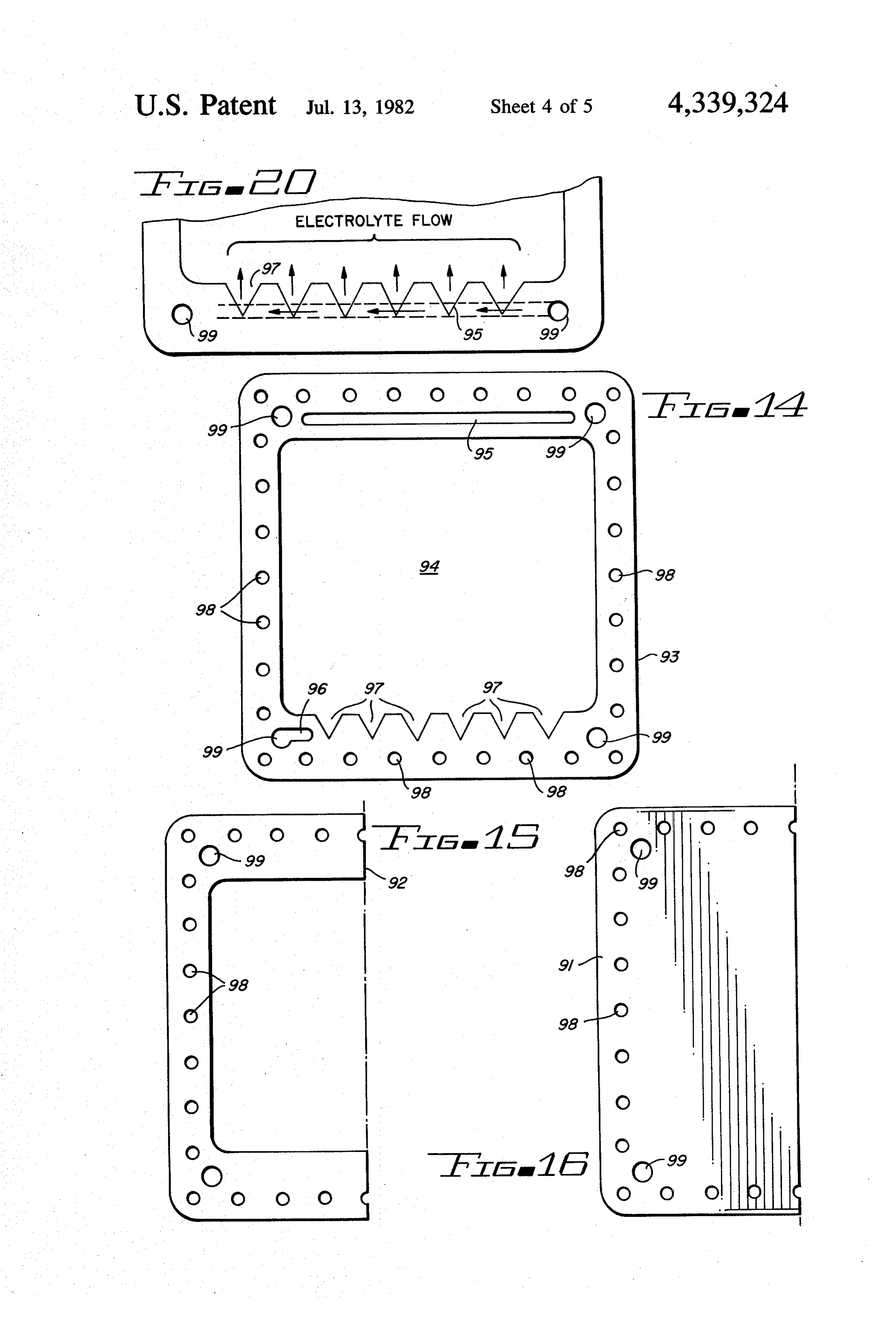
gases. FIG. 19 is a partial plan view of a pair of separator These and other objects and advantages of the inven frames on the other side of the electrode, one turned 180 tion will become apparent as the following description degrees from the other forming adjacent parts of the proceeds and the features of novelty which characterize 10 assembly shown in FIG. 17 and showing the electrolyte this invention will be pointed out with particularity in and gas flow in a second direction; the claims annexed to and forming a part of this specifi FIG. 20 is a partial plan view of the other end of the cation. separator frames shown in FIGS. 18 and 19 illustrating the electrolyte flow into the assembly shown in FIG.
BRIEF DESCRIPTION OF THE DRAWINGS 17; and
The present invention may be more readily described 15 FIG. 21 illustrates a partial cross-sectional view of by reference to the accompanying drawings, in which: two gaskets each on a different side of a nickel foil electrode illustrating how the gasket forms a seal
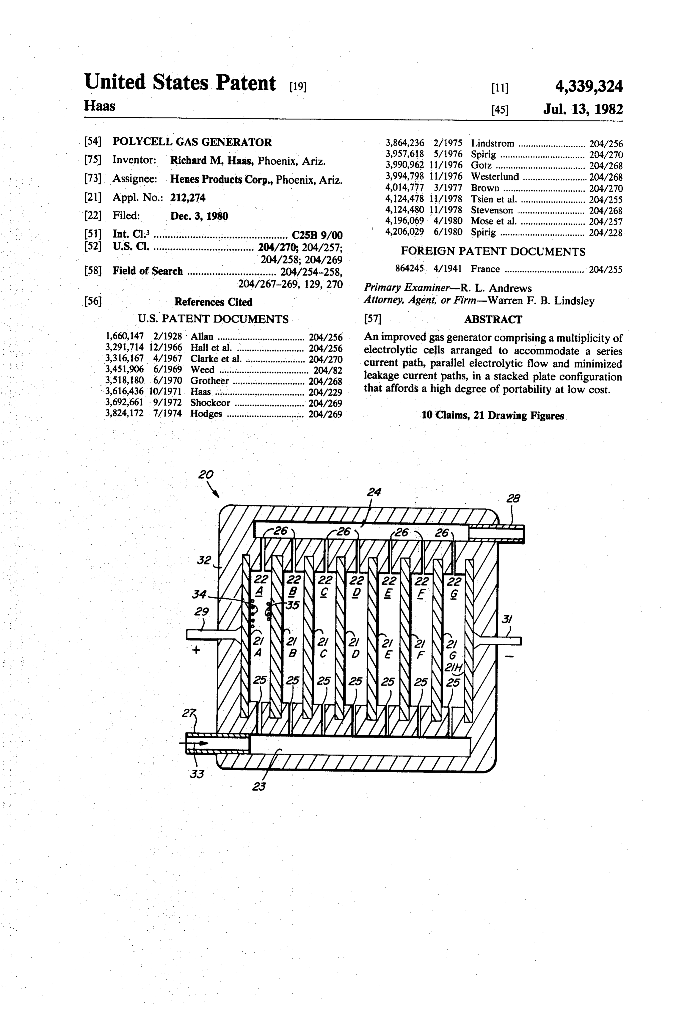
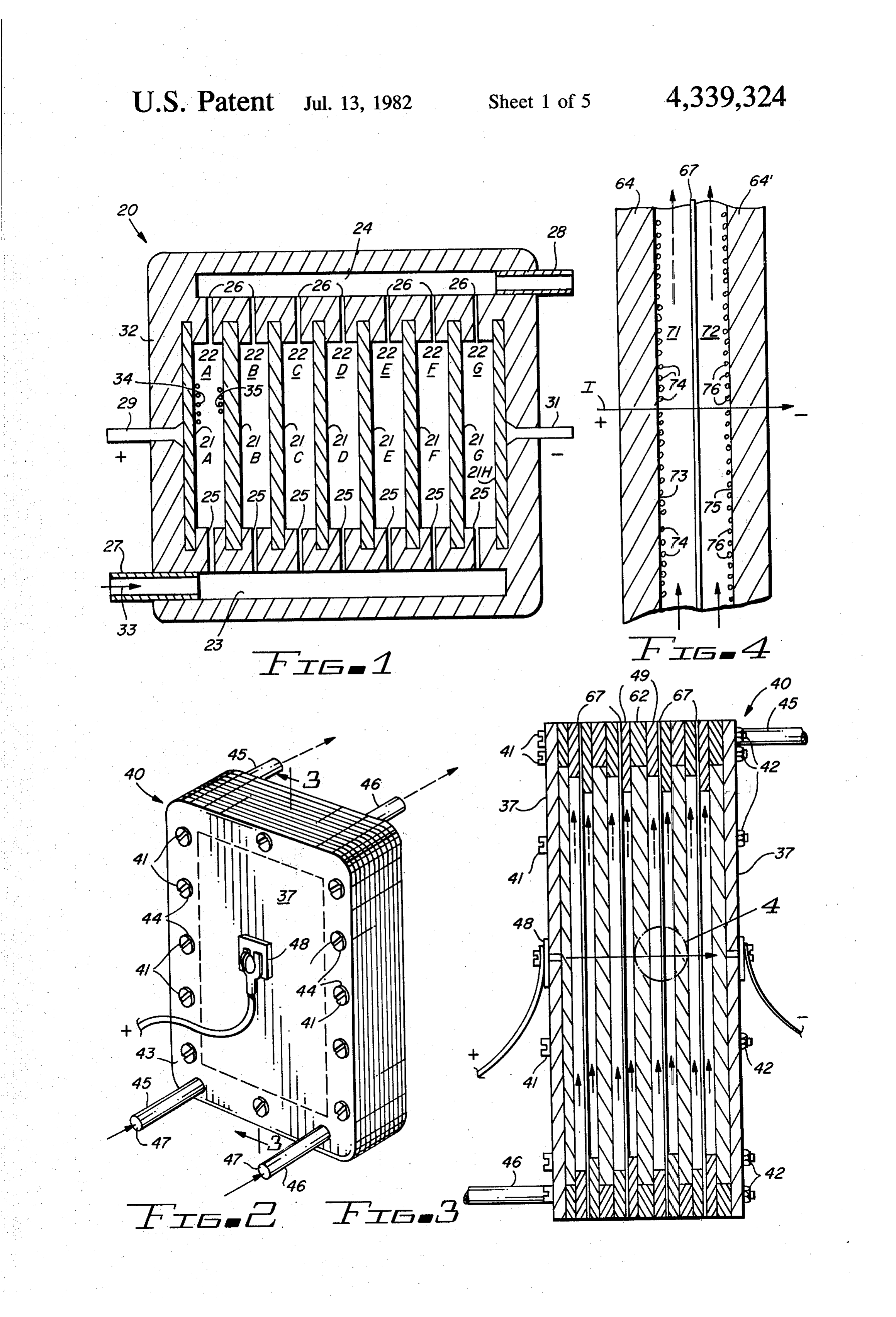
FIG. 1 is a simplified functional diagram of the im around proved gas generator of the invention; the electrolyte and gas flow through holes in the FIG. 2 is a perspective view of a first embodiment of nickel foil plate.
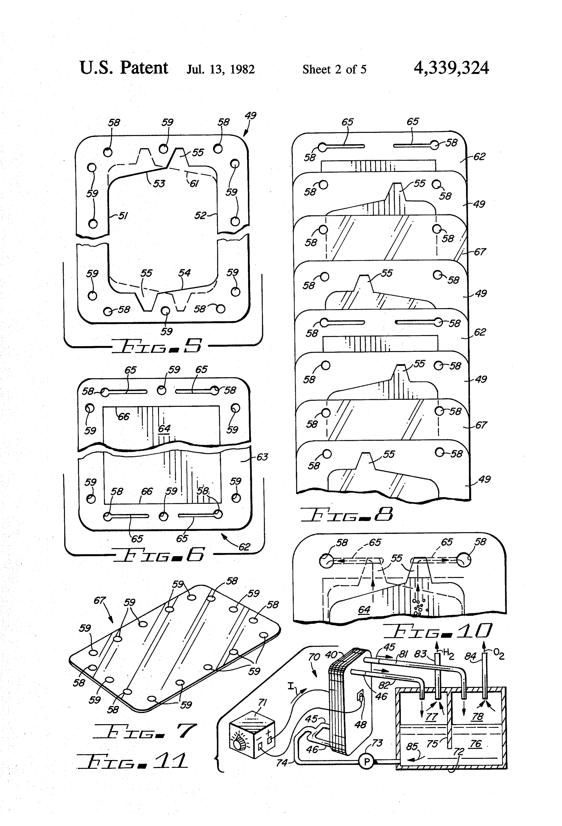
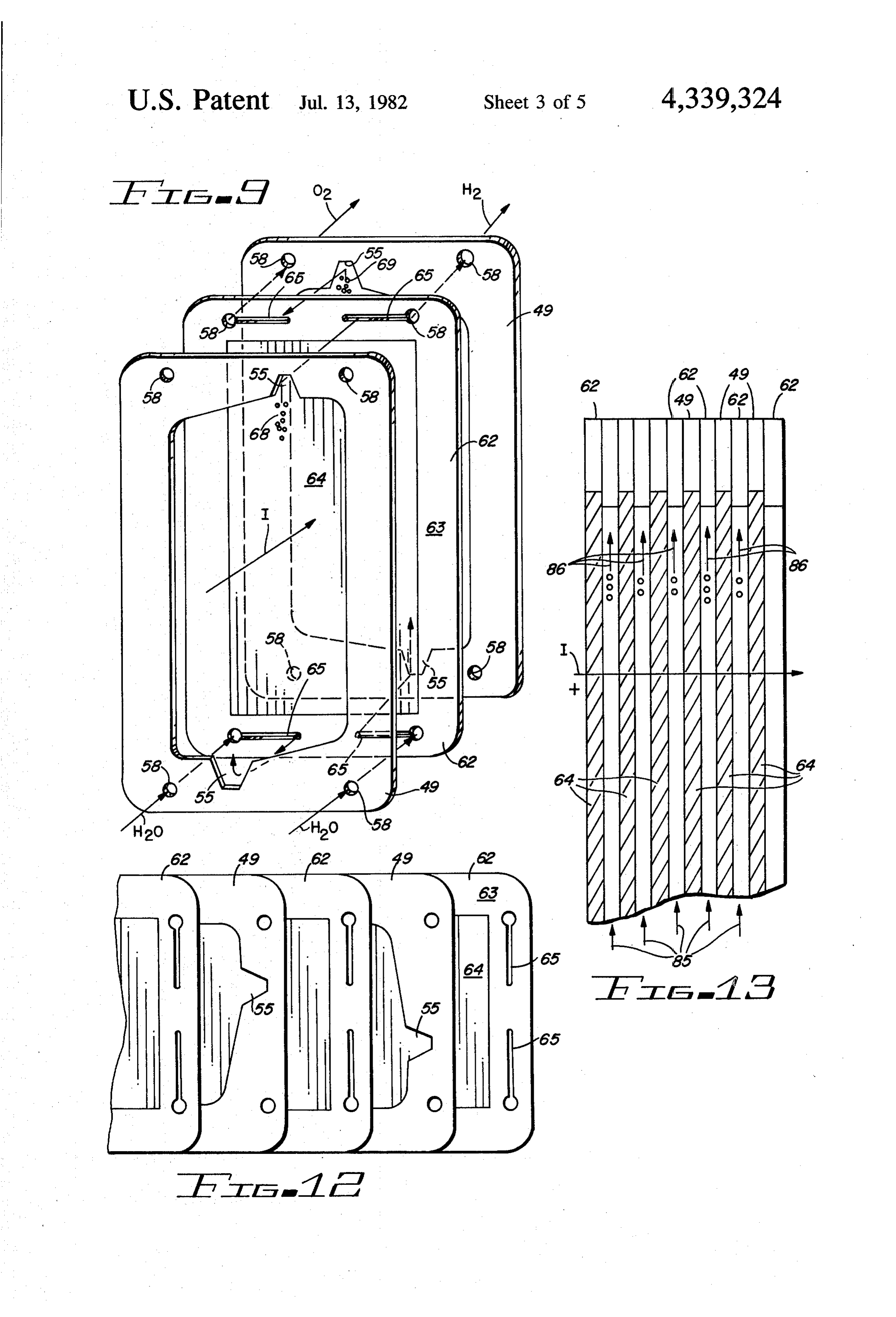
the improved gas generator of the invention; DESCRIPTION OF THE PREFERRED FIG. 3 is a cross-sectional view of FIG. 2 taken along EMBODIMENT the line 3-3; Referring more particularly to the drawings by char FIG. 4 is an enlarged view of the portion of FIG. 3 acters of reference, FIG. 1 discloses an improved gas enclosed by circle 4; m 25 generator 20 comprising parallel, spaced apart plate FIG. 5 is a plan view of a separator frame that is electrodes 21A-21H, electrolysis chambers 22A-22G, employed as an element of the assembly of FIG. 2;
FIG. 6 is a plan view of the electrode and frame an electrolyte inlet manifold 23, a gas and electrolyte outlet manifold 24, inlet ports 25, outlet ports 26, an combination employed as elements of the assembly of electrolyte supply port 27, a gas and electrolyte deliv FIG. 2; 30 ery port 28, a positive terminal 29 and a negative termi FIG. 7 is a perspective view of a cover plate and/or nal 31. The generator 20 is enclosed in a sealed and separator that is employed as an element of the assembly electrically insulated housing 32 forming a cavity of FIG. 2; within which the chambers 22A-22G are formed. FIG. 8 is an exploded view showing a number of the In the particular implementation of generator 20 that individual elements that are stacked together to form 35 is of primary interest to this invention, the generator is the assembly of FIG. 2, the view of FIG. 8 showing the employed in the electrolysis of water for the generation order in which the elements are stacked; of detonating gas. The electrolyte employed is a solu FIG. 9 is an exploded perspective view showing tion of potassium hydroxide (KOH) and distilled water, three key elements of the assembly of FIG. 2 with the the potassium hydroxide being employed to provide elements spaced apart to permit an illustration of the 40 electrical conductivity. The electrodes 21A-21H are electrolyte and gas flow paths through the inlet and flat rectangular plates which may be made from nickel outlet ports; sheet stock.
FIG. 10 is a plan view showing the three elements of In the operation of generator 20, electrolyte 33 enters FIG. 9 stacked together as in the assembly of FIG. 2, port 27 and fills inlet manifold 23. From manifold 23, the broken lines showing contours of hidden elements; 45 the electrolyte enters chambers 22A-22G via the inlet FIG. 11 is a simplified functional diagram showing ports 25, filling chambers 22A-22G and then passes out the gas generator of FIG. 2 connected for operation through the outlet ports 26 into the outlet manifold 24 with an electrolyte tank and a power supply; from which it is finally exhausted through port 28. It FIG. 12 shows the order in which the separator will be immediately recognized that the chambers frames, electrode frames and electrodes are stacked in a 50 22A-22G with their inlet ports 25 and their outlet ports second embodiment of the invention; 26 constitute parallel flow paths between the inlet mani FIG. 13 is a cross-sectional view of the second em fold 23 and the outlet manifold 24. The manifolds 23 and bodiment of the invention in which the elements are 24 are sufficiently large in cross-section to assure mini stacked in the order shown in FIG. 12; mal pressure drops along their lengths. In addition, the FIG. 14 is a plan view of a further modification of a 55 entry port 27 is located at the bottom of generator 20 separator frame employed in the assembly shown in while the delivery port 28 is located at the top of gener FIG. 17; ator 20 so that the total path length traversed by the FIG. 15 is a plan view of one half of a gasket seal electrolyte passing through any one of the several shown in the assembly of FIG. 17 with the other half chambers 22A-22G is the same as that traversed by the not shown being a mirror image of the half shown; 60 electrolyte passing through any of the remaining cham FIG. 16 is a plan view of one half of the electrode bers. These precautions assure that the electrolyte is shown in the assembly of FIG. 17 with the other half delivered to all the chambers at the same pressure and not shown being a mirror image of the half shown; that the flow rate through all the chambers is the same. FIG. 17 is an exploded perspective view of a modifi Electric current flow is from the positive terminal 29 cation of the gas generators shown in FIGS. 1-13 with 65 to electrode 21A, through the electrolyte in chamber the bolt holes of the various separator frames, gasket 22A to electrode 21B, from electrode 21B through seals and electrodes shown in FIGS. 14-16 embodied in chamber 22B to electrode 21C, through chamber 22C to FIG. 17 omitted for the sake of clarity; electrode 21ED, through chamber 22D to electrode 21E,
Page 9
through chamber 22E to electrode 21F through cham through covers 37. A screw terminal 48 is provided at ber 22F to electrode 21G, through chamber 22G to the center of cover 37 with the terminal providing a electrode 21H to negative terminal 31. The electrical conductive path through the cover to a contact button conductivity of the electrodes 21A-21H is high so that (not shown) on the opposite side thereof and also pro the potential difference between adjacent electrodes viding a means for connection to the positive or nega 21A and 21B, 21B and 21C etc. is uniform over their tive terminal of a power supply. Two such covers 37 are mutually confronting surfaces. Current density from employed in generator 40, one on each end of the electrode to electrode through the intervening electro stacked planar elements.
lyte is very uniform because the electrolyte is dense and FIG. 5 illustrates a spacer element 49 in the form of a under constant circulation. 10 rectangular nylon frame. The two longer sides 51 and Because there is a voltage drop from electrode to 52 of element 49 are of uniform width but its ends 53 electrode, a potential difference exists between adjacent and 54 are wider at one side than at the other, the nar chambers. As a result of this difference in potential a row side of end 53 being diagonally opposite the narrow leakage current can flow from each chamber to the side of end 54. Near the narrow side of each of the ends adjacent chamber. Thus, for example, a leakage current 15 53 and 54, a wedge-shaped indentation or notch 55 is flows from chamber 22A to chamber 22B. This leakage provided. This indentation serves as a channel for the current takes two paths. The first path is from chamber flow of electrolyte and gas, as later described. Two 22A through its inlet port 25 to manifold 23, through holes 58 are provided at each end of element 49 which the juxtapositioned inlet port 25 to chamber 22B. The serve as gas and electrolyte passageways; the remaining second path is from chamber 22A through its outlet 20 holes 59 which are spaced about the periphery of ele port 26 to manifold 24, through the juxtapositioned ment 49 receive screws 41 of gas generator 40. The outlet port 26 to chamber 22B. In both cases the leakage broken line 61 shows the contours of an identical ele currents are, of course, carried by the electrolyte. Leak ment 49 that has been reversed to position the indenta age currents flow in like manners from chamber 22B to tions 55 at the opposite sides of ends 53 and 54 from chamber 22C, from chamber 22C to chamber 22D, etc. 25 their positions in the solid line representation of element These leakage currents are non-productive in terms of 49. - -
gas generation. They consume power and thus reduce FIG. 6 illustrates an electrode assembly 62 compris operating efficiency, and they produce undesirable ing a rectangular nylon electrode frame 63 and a rectan heating of the electrolyte. gular plate electrode 64. Electrode 64 is formed of To minimize the leakage currents, the inlet and outlet 30 nickel when used in a detonating gas generator. Frame ports 25 and 26, respectively, are small in cross-sec 63 comprises four sides of uniform width with a rectan tional area. The length of each port should preferably gular central opening appropriately dimensioned to be several times greater than the span or diameter of its receive electrode 64 in a snug fit. The outer dimensions cross-sectional configuration. of frame 63 are identical to those of element 49, and Within each of the chambers 22A-22G current flows 35 mating, identically spaced and positioned holes 58 are from the more positive electrode to the more negative provided for gas and electrolyte passageways. Identi electrode. Thus the face of the plate electrode from cally positioned screw holes 59 are also provided as in which the current flows serves as the anode for that the case of element 49. A narrow slot 65 extends in chamber while the face of the other juxtapositioned wardly from each of the four holes 58 with the slots plate electrode to which the current flows becomes the 40 running parallel with the end members 66 of frame 63 cathode. It will be recognized that the opposite face of and ending just short of the screw hole 59 located at the the electrode serving as a cathode for chamber 22A center of the corresponding end member 66. Slots 65 serves as the anode for chamber 22B. The electrode 21B serve as gas and electrolyte passages in the assembled and the electrodes 21C-21G are thus known as bi-polar generator 40 as later described.
electrodes, each having one face employed as an anode 45 A cellophane separator element 67, also employed as and the opposite face as a cathode. Within each cham an element of gas generator 40 is shown in FIG. 7. This ber the current flow from anode to cathode results in element has an outer dimension matching those of ele the generation of oxygen and hydrogen, the oxygen 24 ments 49 and frames 63 and is provided with identically collecting at the anode and the hydrogen 35 collecting positioned mating holes 58 and 59.
at the cathode. Both the oxygen and the hydrogen are 50 In gas generator 40 the elements just described are swept out of the chamber by the electrolyte flowing stacked, one directly on top of the other in the order through the chamber, the gas and electrolyte mixture shown in FIG.8. From the top of the figure, the order passing through the outlet port 26 of each chamber into as shown begins with an electrode assembly 62 followed the outlet manifold 24 and thence through outlet port 28 by a spacer element 49, a cellophane separator element to a collection chamber (not shown in FIG. 1). 55 67, another spacer element 49, another electrode assem Gas generator 40 of FIGS. 2 and 3 constitutes an bly 62, spacer element 49, separator element 67, spacer other embodiment of the invention and comprises a element 49, ... etc. Each successive spacer element 49 number of flat or planar elements stacked together be is reversed relative to the previous spacer element so tween end covers or plates 37 and secured as a unit by that the position of the indentation 55 is staggered from means of bolts 41 and nuts 42. one side to the other. In the cross-sectional view of the End covers 37 comprise rectangular plates 43 molded generator 40 as shown in FIG. 3, the elements 49, 62 from nylon or a similar electrically insulating material and 67 are seen to be stacked in the same order as just that is impervious to moisture. Holes 44 about its pe described.
riphery are provided to receive bolts 41. At each end, The interrelationships between the holes 58, slots 65 two electrolyte (or gas and electrolyte) inlet or outlet 65 and indentations 55 as they cooperate to form the inlet ports 45 and 46 are provided, the ports 45 and 46 being and outlet ports and manifolds for the electrolyte and hollow tubular and/or cylindrical configurations with generated gas is shown in FIGS. 9 and 10. FIGS. 9 and their central openings 47 providing passageways 10 show two spacer elements 49 stacked, one on each
Page 10
side of an electrode assembly 62. One of the spacer sive spacer elements 49 are reversed to stagger the posi elements 49 is reversed relative to the other so that one tions of the indentations 55, the oxygen is consistently of the indentations 55 is positioned to the left and one to diverted to the left and the hydrogen is diverted to the the right of the center line of the gas generator. right side of the gas generator as described. With the aid As is also shown in FIG. 9, the holes 58 of the two of the cellophane separator elements 67, the generated spacer elements 49 and the holes 58 of the electrode oxygen and hydrogen gases are separated and delivered assembly 62 are mutually aligned to form common pas separately from gas generator 40. sageways running perpendicularly through the stacked Further clarification of the means by which the oxy elements. The four holes 58 in each element form to gen and hydrogen are isolated from each other in gas gether with the four holes 58 in all the other elements, O generator 40 is facilitated with reference to FIGS. 3 and four passageways through the stacked assembly, 4. As shown most clearly in FIG. 4, the electric current It will also be noted from FIG. 9 that the end of slot I flows from left to right through a first electrode 64, a 65 extending from the left-hand hole 58 of electrode sheet of electrolyte 71, a separator element 67, a second assembly 62 communicates with the indentation 55 of sheet of electrolyte 72 and through a second electrode the spacer element 49 on the right side of the electrode 15 64". The sheets of electrolyte 71 and 72 flow within the assembly while the end of the other slot 65 extending window openings of spacer elements 49 positioned be from the right-hand hole 58 of electrode assembly com tween electrodes 64 and 64' and separator element 67. municates with the indentation 55 of the spacer element The right hand surface 73 of electrode 64 is an anode 49 on the near or left side of the electrode assembly 62. and gas 74 generated at that surface is oxygen while the It will thus be recognized that the moving electrolyte 20 left hand surface 75 of electrode 64' is a cathode and gas and the gas generated on the far surface of the electrode 76 generated at the surface is hydrogen. While the cello 64 is free to flow upward along the surface of electrode phane separator element 67 readily passes the electric 64 into the indentation 55 of the far or right sided ele current I, it effectively blocks the passage of oxygen ment 49 through slot 65 and into the passageway generated at surface 73 from mixing with hydrogen formed by the aligned holes 58 at the upper left-hand generated at surface 75.
corner of the stacked elements shown in FIG. 2. Simi The electrolyte sheets or bodies of fluid 71 and 72 are larly, electrolyte and gas generated on the near surface quite narrow, their thicknesses being equal to the thick of the electrode 64 may follow the near surface of elec ness of the spacer element 49 which may be readily trode 64 into indentation 55 of spacer element 49 on the made as thin as desired. Close electrode spacing is thus near or left side of the assembly shown in FIG. 9 and 30 achieved in this assembly without exposure to problems into the other slot 65 and thence into the other passage involving close mechanical tolerances. Because the formed by the aligned holes 58 at the upper right-hand adjacent electrodes 64 and 64' are closely spaced the corner of the stacked elements shown in FIG. 2. ionic path length is short which promotes conductivity. The electrolyte (H2O+KOH) enters the two pas Furthermore, the close electrode spacing assures a max sages at the bottom formed by the aligned holes 58. 35 imum degree of contact between the electrolyte circu From these two passages the electrolyte follows slots 65 lated and the electrode surfaces where the gas is gener of electrode frame 63 to indentations 55 of spacer ele ated. Thus highly efficient and effective gas production ments 49. Electrolyte reaching indentation 55 of ele, is achieved in an assembly that inherently permits the ment 49 on the near side as shown in FIGS. 9 and 10 separation of the oxygen and hydrogen gases. flows upward out of indentation 55 along the near sur 40 In a totally assembled generator 40, the elements are face of electrode 64 while electrolyte emerging from stacked in the order shown in FIG. 8 with an electrode indentation 55 of element 49 on the far side rises along assembly 62 positioned at both ends of the stack. An end the far surface of electrode 64. If current I flows per cover 37 is then positioned at both ends of the stack of pendicularly into the near face of electrode 64 from the elements, the holes 44 of cover 37 aligned with the holes near side, the near face of electrode 64 becomes a cath 45 59 of the elements 49, 62 and 67. The ports 45 and 46 of ode and the face of electrode 64 on the far side becomes the front cover are preferably positioned at the bottom an anode. The gas generated at the near surface is hy of the assembly, as shown in FIGS. 2 and 3, while the drogen and the gas generated at the far surface is oxy ports 45 and 46 of the rear cover are positioned at the gen. Both gases move upward along with the flow of top (or vice versa), for the equalization of the parallel the electrolyte, the hydrogen 68 at the near surface 50 electrolyte path lengths through the individual cells. finds its way into indentation 55 of the near spacer ele With elements 49, 62 and 67 and the front and rear ment 49 following slot 65 into the passageway formed covers 37 stacked and aligned, as just described, screws by the aligned holes 58 in the upper right hand corner of 41 are passed through holes 44 and 59 and are secured in the gas generator, and the oxygen 69 generated on the place by means of nuts 42. When the nuts are properly far surface flows into indentation 55 of element 49 in the 55 tightened a sealed assembly is achieved in which the far side, through slot 65 into the passageway formed by frames of the elements are tightly compressed together the aligned holes 58 in the upper left-hand corner of the so that the electrolyte is effectively contained. The gas generator. containment of the electrolyte may, of course, be en Slots 65 thus constitute the inlet and outlet ports hanced by prior coating of the mating element surfaces corresponding to ports 25 and 26 of gas generator 20. 60 with a joint compound or sealing material. The long and narrow proportions of slots 65 afford the FIG. 11 illustrates a complete gas generation system high electrical impedance needed for the inlet and out 70 incorporating generator 40 shown in FIG. 3, a source let ports to assure minimization of leakage currents. of electric current 71, an electrolyte and gas separator The cellophane separator elements 67, not shown in tank 72 and a pump 73. Pump 73 is serially connected in FIGS. 9 and 10, but positioned ahead of the near ele 65 a tube 74 leading from the bottom of tank 72 to inlet ment 49 and immediately to the rear of the far element ports 45 and 46 of gas generator 40. A vertical wall 75 49, readily pass the ionic current flow I, but block the projecting downward from the top cover of tank 72 lateral flow of the generated gases. Because the succes extends below the surface of the contained electrolyte
Page 11
76 to form two chambers 77 and 78 for gas collection This concept was accomplished by using two types of above the surface of the electrolyte. A tube 81 connects plastic frames and rectangular, electrode plates which chamber 78 to outlet port 45 of gas generator 40 and a were stacked into a cell assembly. The stacking arrange tube 82 connects chamber 77 to outlet port 46. Gas ment and the flow pattern for this type of multicell delivery lines 83 and 84 are provided for the extraction 5 assembly has been described with reference to FIGS. of gas from chambers 77 and 78, respectively. 1-13.
The positive terminal of source 71 is connected to FIGS. 14-21 disclose a further embodiment of the terminal 48 at the inlet side of gas generator 40 and the invention wherein gasket seals are utilized between the negative terminal of source 71 is connected to terminal electrodes and the polycell frames to prevent leakage of 48 at the outlet side of gas generator 40, both terminals 10 the electrolyte between the frames. Further, the em making contact with the adjacent end electrode 64 so bodiments of FIGS. 14-21 reduce the thickness of the that current is supplied by source 71 and flows serially electrodes of those shown in . FIGS. 1-13 to reduce through the stacked elements of gas generator 40, as material costs and incorporate multiple inlet and outlet heretofore described. ports in each cell chamber to promote a uniform flow Pump 73 draws electrolyte 76 from the bottom of 15 pattern through each chamber.
tank 72 and delivers its to inlet ports 45 and 46 of gas As shown in FIG. 17 the gas generator assembly 90 generator 40 in which it follows the parallel paths comprises a plurality of nickle foil electrodes 91, gasket through the cells formed between the stacked elec seals 92 and polycell frames 93 in a particular array. trodes 64. The generated oxygen is discharged at port FIGS. 14-16 illustrate the polycell frame 93, gasket 45 and the generated hydrogen is discharged at port 46. 20 92 and nickle foil electrodes 91 in more detail than that Oxygen is carried by line 81 to chamber 78 along with shown in FIG. 17 for purposes of clarity. residual electrolyte and the hydrogen is carried with The polycell frame 93 is the most essential part of the residual electrolyte by line 82 to chamber 77. The resid gas generator assembly 90 and is designed to form a cell 'ual electrolyte is collected in tank 72 while the hydro chamber in its hollow interior 94, a cross feed channel gen and oxygen are removed through lines 83 and 84, 25 95, an orientation slot 96, a plurality of spaced notches respectively. - 97 at one end thereof, a plurality of gasket screw holes While the gas generator described is designed to 98 and feed through holes 99 for the electrolyte and deliver the oxygen and hydrogen products separately, generated gas flow. The feed-through holes 99, cross elements 49 and 62 may be employed in another simple feed channel 95, port notches 97 and the orientation slot arrangement if such separate gas delivery is not re- 30 95 are arranged such that two polycell frames 93 placed quired as, for example, when the desired end product is adjacent to each other may be rotated 180 degrees as detonating gas for use in welding applications. shown to provide, a desired electrolyte and gas flow For a gas generator of the latter type, elements 49 and pattern.
62 are stacked in the order shown in FIGS. 12 and 13. The nickel foil electrode 91 comprises a very thin Beginning from the right or left of the assembly shown, 35 electrode of approximately 0.003 inches in thickness. the order begins with an electrode assembly 62 fol Not only does this relatively thin electrode save mate lowed by a spacer element 49, another electrode assem rial over that of the structure shown in FIGS. 1-13 but bly 62, a spacer assembly 49, etc. Each successive also renders the electrode more flexible so that it can spacer element 49 is reversed as shown to prevent coin conform to minor irregularities within the assembly. cidence of voids in the region of the indentations 55 on 40 The need for gaskets 92 to provide good seals be opposite sides of the electrodes 64 at which points leak tween the polycell frames 93 and the electrodes 91 and age currents might otherwise be introduced. adjacent frames 93 within the gas generator 90 is depen In the cross-sectional view of FIG. 13, elements 49 dent on the flatness and uniformity of the parts used in and 62 are stacked in the order just described with an building the multi-cell gas generator. While it is possible electrode assembly 62 at each end. Current flow I is 45 to make a few precise parts and thus eliminate the need from left to right through the stacked elements and for gaskets, in production a gasket seal of the electrodes electrolyte 85 flows from the bottom to the top of the will provide more consistent results. assembly in parallel paths between adjacent electrodes Since each row of feed through holes 99 within the 64. The electrolyte flows in thin sheets orthogonally various plates of a polycell assembly stack form a mani arranged with respect to the flow of electric current. 50 fold, it is important to recognize that leakage currents The generated detonating gas 86 is exhausted at the top can flow between any two electrode plates 91 wherever of the assembly through outlet ports formed in commu an electrolyte path exists. To inhibit leakage currents nication with indentations 55 and the slots 65 formed, within any one of the manifolds the feed through holes respectively, in spacer elements 49 and the electrode 99 in each electrode 91 are insulated as shown in FIG. frames 63. The perpendicular or orthogonal relation- 55 21. The insulation of these holes occurs when the gas ship between electric current and electrolyte flow paths kets formed of resilient plastic material are compressed results in a minimization of the electric current path under the pressure of the assembly bolts and nuts 41 and length, and thus is an enhancement of operating effi 42, respectively. This resilient material is forced over ciency. The parallel electrolyte flow under pressure . the edges of these holes 99 to insulate the edges of the assures a maximum surface contact of high density elec- 60 holes from the electrolyte flowing therethrough. trolyte, minimally diminished by generated gas over The basic operation of the multicell generator shown much of the electrode surface for a high rate of gas in FIGS. 14-21 is similar to the operation of the gas generation. This condition is further enhanced as elec generator shown and described relative to FIGS. 12 and trolyte flow rates are increased. 13. Electrolyte is introduced under pressure through The previously disclosed embodiments of the multi- 65 the inlet port 99 and fills all of the cell chambers 94 ple cell gas generator are based on the concept of circu formed by polycell frames 93 arranged on each side of lating under pressure electrolyte through narrow cham the middle electrode 91 shown in FIG. 17. An electric bers within a cavity of the housing of the gas generator. power source is connected to terminals 48 attached to
Page 12
end plates or electrodes 91. As soon as current flows each chamber having inlet and outlet ports extending through the gas generator, gas generation begins and through said housing, the lengths of the path the gas bubbles are carried or move upward to both through said housing of each port being greater outlet manifolds 99 simultaneously, as shown in FIG. than their cross-sectional width dimension, 17. an inlet manifold connected to each of said inlet ports As noted from FIGS. 1-11, a gas generator produc of said chambers for containing electrolyte for ing hydrogen and oxygen gases in a separated form has circulation through said chambers, been disclosed. The assembly shown in FIG. 17 can be an outlet manifold connected to each of said outlet easily modified to produce a discrete gas generator by ports of said chambers, replacing every other electrode 91 by an identical sheet 10 said outlet manifold being larger than said inlet mani of cellophane. For example, the electrode 91 in the fold to eliminate any pressure buildup of electro center of the assembly shown in FIG. 17 may be re lyte within said chamber, and placed by a sheet of cellophane and this generator will means for conducting electric current through said then separate the hydrogen from the oxygen gases as chambers in a series arrangement laterally to the they are being generated. Because of this cellophane 15 flow of electrolyte through said chambers. separator in between electrodes, the gas generated at 3. A gas generator comprising in combination: anode surfaces does not mix with gas generated at the a plurality of flat metal electrodes each mounted in an cathode surfaces. electrically insulating frame and positioned in an It should also be noted that the multiple inlet and aligned parallel array, outlet ports formed by the spaced notches 97 into the 20 a plurality of insulating spacer elements each com cross feed channels 95 promotes a uniform flow pattern prising a frame encircling an opening extending of the electrolyte and gases through each chamber and therethrough with one element mounted between out of the gas generator. each pair of said adjacent electrodes, In tests performed using a prototype of the gas gener a pair of cover plates one mounted at each end of the ator of the invention, exceptionally high rates of gas 25 assembly of said electrodes and spacer elements generation were achieved, the exhausted mixture of gas with each plate serving as an electrical terminal for and electrolyte exhibiting an unusually high content of the gas generator, gas. The high ratio of gas to residual electrolyte ap each frame of said electrodes and said spacer ele peared to be sustained as the electrolyte flow rate was ments and said cover, plates comprising opposed increased. 30 end portions,
A highly efficient and effective gas generator is thus each of the frames of said elements being provided constructed by using the principles taught in the present with at least a pair of notches along its inner pe invention. riphery one arranged in each end portion, Although but a few embodiments of the invention means for clamping the plurality of electrodes, spacer have been illustrated and described, it will be apparent 35 elements and cover plates together so as to provide to those skilled in the art that various changes and modi a plurality of cells one between each pair of adja fications may be made therein without departing from cent electrodes, the spirit of the invention or from the scope of the ap the frames of said electrodes and spacer elements and pended claims. said cover plates each being provided with a pair of What is claimed is: spaced apertures extending therethrough in each 1. A polycell gas generator comprising: end portion thereof with similarly positioned aper a housing defining a cavity, tures in each end portion of said electrodes, spacer a plurality of parallelly arranged chambers in said elements and plates being interconnected in axial housing each defining a gas generating cell, alignment, each chamber comprising a pair of spacedly posi 45 a pair of slots arranged in each frame of said elec tioned electrode plates defining therebetween a trodes in each end portion thereof with one slot passageway for the simultaneous circulation under extending laterally from each aperture toward the pressure of electrolyte through each of said cham longitudinal axis of said frame and communicating bers, with one of the notches of a spacer element ar each passageway having inlet and outlet ports extend 50 ranged on a predetermined side thereof, ing through said housing, the lengths of the path said apertures in one end portion of the spacer ele through said housing of each port being greater ments being connectable to a source of electrolyte than its cross-sectional width dimension, which flows through these apertures, the slots and means for serially conducting ionic current across notches of said spacer elements and into the open said chambers in a series arrangement laterally to 55 ing in said spacer elements between said electrodes the flow of electrolyte through said chambers, in a parallel simultaneous manner and out said means for separating the gases generated at juxtaposi notches and the slots and apertures at the other end tioned surfaces of the electrode plates of each portion of said spacer elements. chamber, and 4. The gas generator set forth in claim 3 wherein: means for collecting like gases from each of said 60 the distance of electrolyte flow between adjacent chambers and discharging the collected gases sepa cells through said apertures and said slots is greater rately from said generator. than the distance between juxtapositioned elec 2. A polycell gas generator comprising: trodes.
a housing defining a cavity, 5. The gas generator set forth in claim 3 wherein: a plurality of parallel chambers within said housing 65 the length of the path through said apertures and said each chamber defining a gas generating cell, slots in said spacer elements is greater than the a plurality of electrode plates one electrode plate mean cross-sectional dimension of said path. positioned between adjacent chambers, 6. The gas generator set forth in claim 3 wherein:
Page 13
said notches in each end portion of said frames of said 9. The gas generator set forth in claim 7 in further spacer elements is positioned off center from the combination with:
longitudinal axis of the spacer element. means for collecting and discharging like gases gener 7. The gas generator set forth in claim 6 wherein: ated in each of said cells separately from said gen each of said spacer elements is alternatively posi erator.
tioned as a mirror image of the other in said stack 10. The gas generator set forth in claim 3 wherein: arrangement. said spacer elements are formed of pliable material, and 8. The gas generator set forth in claim 7 in further said pliable material when clamped between said combination with: O a gas impervious spacer member positioned between electrodes is distorted around the periphery of said each electrode in said stack arrangement for sepa apertures in said electrodes to insulate these elec rating hydrogen and oxygen gases generated on trodes from the electrolyte flowing through said apertures in saidk electrodes.
juxtapositioned surfaces of adjacent electrodes. k k k sk
Provenance
- Collection
- Cited prior art
- Original PDF
- patentimages.storage.googleapis.com →
- Filed
- 1980-12-03
- Pages
- 13
- Method
- pdftotext (the PDF's own text layer) + pdftoppm 300dpi page scans
- Source
- Google Patents bibliographic record
- Granted
- 1982-07-13
- Inventors
- Richard M. Haas; Henes Products Corp
- Transcribed from
- patentimages.storage.googleapis.com →