patent · US4107008
Electrolysis method for producing hydrogen and oxygen
15 August 1978
Page 1 — bibliographic record
United States Patent (19) 11) 4,107,008 Horvath (45) Aug. 15, 1978 54 ELECTROLYSIS METHOD FOR (58) Field of Search. 204/129
PRODUCING HYDROGEN AND OXYGEN
75 Inventor: Stephen Horvath, St. Ives, Australia U.S. PATENT DOCUMENTS 73) Assignee: Beeston Company Limited, Hong 2,016,442 10/1935 Kilgus .................................. 204/129 Kong, Hong Kong 3,207,684 9/1965 Dotts ................................ 204/180 R 21) Appl. No.: 753,610 3,719,583 3/1973 Ustick .............................. 204/180 R 22 Filed: Dec. 22, 1976 Primary Examiner-R. L. Andrews Attorney, Agent, or Firm-Biebel, French & Nauman
Related U.S. Application Data 57 ABSTRACT (63. Continuation-in-part of Ser. No. 586,080, Jun, 16, 1975, A novel electrolytic cell produces a mixture of highly abandoned, and Ser. No. 632,579, Nov. 17, 1975, said ionized hydrogen and oxygen gases by a method com Ser. No. 586,080, is a continuation-in-part of Ser. No. bining electrolysis and radiolysis of an aqueous electro
No. 632,579, is a continuation-in-part of Ser. No. lyte. The electrolyte, which may be a 25% of potassium 527,085, Nov. 25, 1974, Pat. No. 3,980,053, said Ser. -hydroxide, is introduced into the cell and is simulta No. 527,083, and Ser. No. 527,085, each is a neously subjected to an electrolysing current and in continuation-in-part of Ser. No. 485,498, Jul. 3, 1974, tense irradiation by electromagnetic radiation of fre abandoned.
quency less than 100 meters.
(51) int. Cl’................................................ C25B/04 52) U.S. C. .................................................... 204/129 14 Claims, 26 Drawing Figures
85 Saskff
EXEIf
SI 4é affilians
N1 NN 4
S. 35-47 77-ENU s SK33
SNES SE
NN, NESNSSESSEER
Page 2
Drawing sheet — no readable text.
Page 3
Drawing sheet — no readable text.
Page 4
Drawing sheet — no readable text.
Page 5
Drawing sheet — no readable text.
Page 6
Drawing sheet — no readable text.
Page 7
Drawing sheet — no readable text.
Page 8
Drawing sheet — no readable text.
Page 9
Drawing sheet — no readable text.
Page 10
Drawing sheet — no readable text.
Page 11
Drawing sheet — no readable text.
Page 12
Drawing sheet — no readable text.
Page 13
Drawing sheet — no readable text.
Page 14
Drawing sheet — no readable text.
Page 15
ELECTROLYSIS METHOD FOR PRODUCING SUMMARY OF THE INVENTION HYDROGEN AND OXYGEN The present invention provides for an electrolysis CROSS REFERENCE TO RELATED process in which radiolysis is also present. It is found APPLICATIONS that with the combination of electrolysis and radiolysis the yield of decomposition products can be greater than
This application is a continuation-in-part of applica that achieved by either a simple electrolysis process or tion Ser. No. 586,080, filed June 16, 1975, (now aban simple radiolysis. The yield rate can be very much in doned) which is a continuation-in-part of Ser. No. proved in the combined electrolysis and radiolysis pro 527,083 filed Nov. 25, 1974 (now U.S. Pat. No. 10 cess by providing a magnetic field in the electrolytic 3,954,592), which is a continuation-in-part of Ser. No. conductor which provides preferred paths for the high 485,498, filed July 3, 1974 and now abandoned. This speed photons of the short wave electromagnetic radia application is also a continuation-in-part of application tion and also for the ions in the electrolytic conductor Ser. No. 632,579, filed Nov. 17, 1975, which is a con thereby increasing the possibility for collision between tinuation-in-part of Ser. No. 527,085, filed Nov. 25, 1974 15 the electrons and the ions with a subsequent improved (now U.S. Pat. No. 3,980,053), which is a continuation radiolysis yield.
in-part of said Ser. No. 485,498. In one method according to the invention, pulses of BACKGROUND OF THE INVENTION high voltage electrical energy are applied between the anode and cathode of an electrolytic cell in such a man
This invention relates to the general field of electroly 20 ner as to generate the necessary short wave length radi sis and has particular, but not exclusive, application to ation for radiolysis. In another method according to the the electrolysis of water to form hydrogen and oxygen. invention pulses of high voltage electrical energy are In an electrolysis process a potential difference is discharged in one or more short wave length radiation applied between an anode and a cathode in contact with generators separate from the anode and cathode but an electrolytic conductor to produce an electric current 25 disposed such that the electrolytic conductor within the through the electrolytic conductor. cell is irradiated by the short wave radiation produced Many molten salts and hydroxides are electrolytic thereby. The high voltage pulses of electrical energy conductors but usually the conductor is a solution of a can be generated by a quite modest direct current input substance which dissociates in the solution to form ions. supplied and the methods according to the invention The term “electrolyte' will be used herein to refer to a 30 will produce a greatly increased yield of decomposition substance which dissociates into ions, at least to some products over that which could be achieved by passing extent, when dissolved in a suitable solvent. The result the supply current through the electrolytic conductor. ing solution will be referred to as an "electrolyte solu The invention also provides apparatus adapted to tion.' 35 practise the methods of the invention. In a simple electrolysis porcess the mass of substance As previously mentioned, the invention is particu liberated at an anode or cathode is, in accordance with larly applicable to the decomposition of water or aque Faraday's laws of electrolysis, strictly proportional to ous solutions to generate hydrogen and oxygen gases the quantity of electricity passed between the anode and and, in order that the invention may be more fully ex cathode. The rate of decomposition of the electrolyte is 40 plained, apparatus designed specifically for such gener thus limited and it is generally uneconomical for exam ation of hydrogen and oxygen will now be described in ple, to generate hydrogen and oxygen from water com detail with reference to the accompanying drawings. mercially by an electrolysis process.
it is known that compounds, including electrolytes BRIEF DESCRIPTION OF THE DRAWINGS such as water, can be decomposed into their constituent 45 In the drawings:
elements by irradiation with short wave electromag FIG. 1 is a circuit diagram for one apparatus con netic radiation. Such radiation induced dissociation or structed in accordance with the invention; decomposition may be termed "radiolysis'. For exam FIG. 2 is a plan view of an electrolytic cell of the ple, a paper by Dr. Akibumi Danno entitled "Producing apparatus;
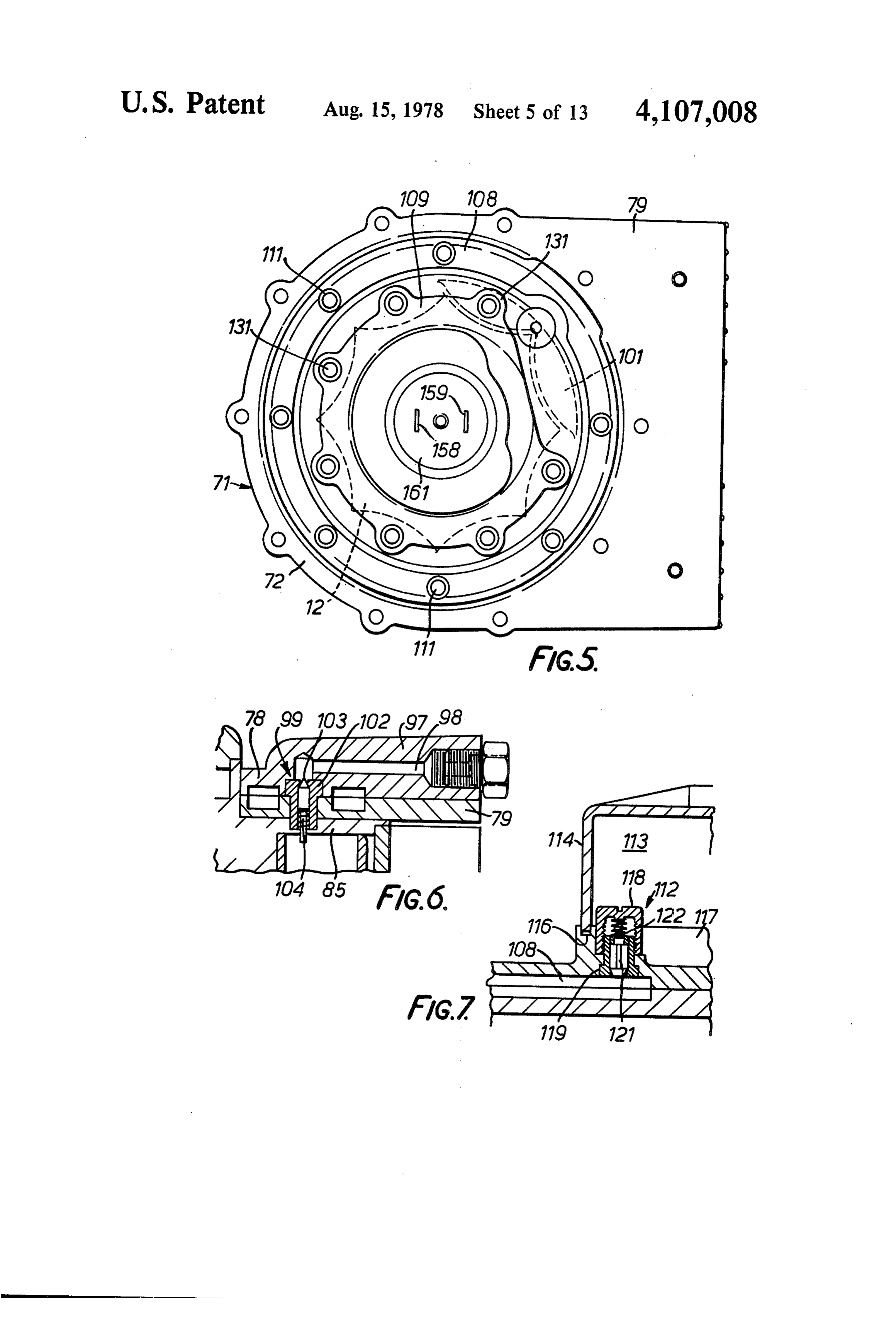
Hydrogen with Nuclear Energy" published in the 50 FIG. 3 is a cross-section on the line 3-3 in FIG. 2; “Chemical Economy and Engineering Review' of FIG. 4 is a cross-section on the line 4-4 in FIG. 3; June, 1974 describes in some detail the radiolysis of FIG. 5 is a plan view of the electrolytic cell with water and a number of hydrocarbons with an explana certain upper parts removed;
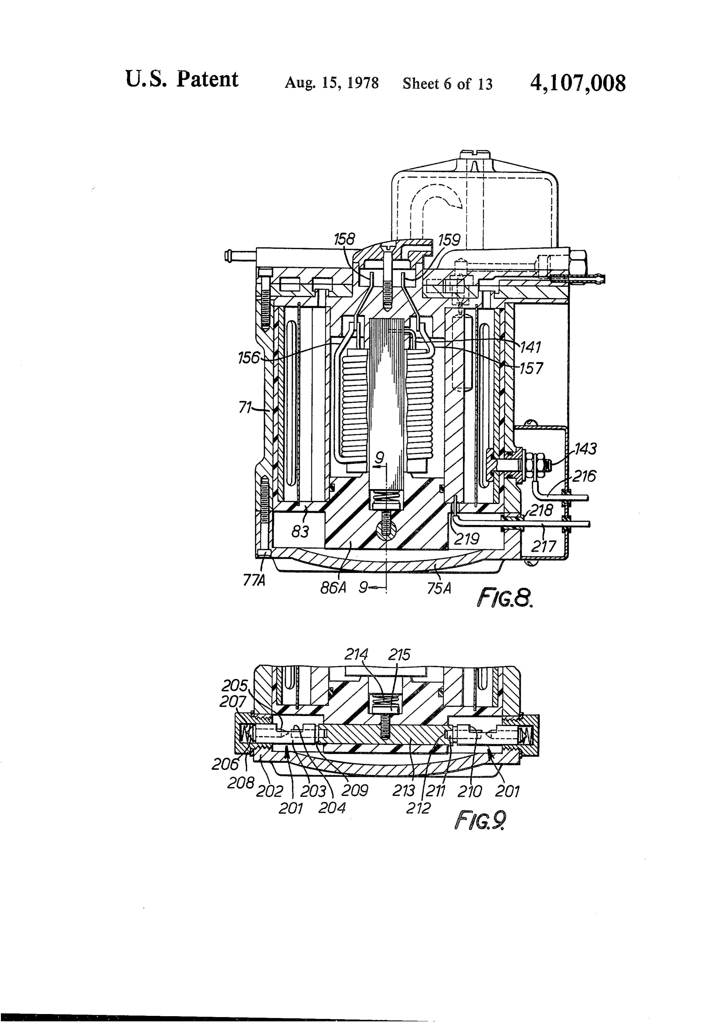
tion of the elementary reactions involved in such radiol FIG. 6 is a cross-section on the line 6-6 in FIG. 2; ysis. Briefly, it is found that irradiation with short wave 55 FIG. 7 is a cross-section on the line 7-7 in FIG. 2; x-rays or gamma rays, i.e. electromagnetic radiation of FIG. 8 is a vertical cross-section through a modified wave length less than 100 meters, results in direct form of electrolytic cell;
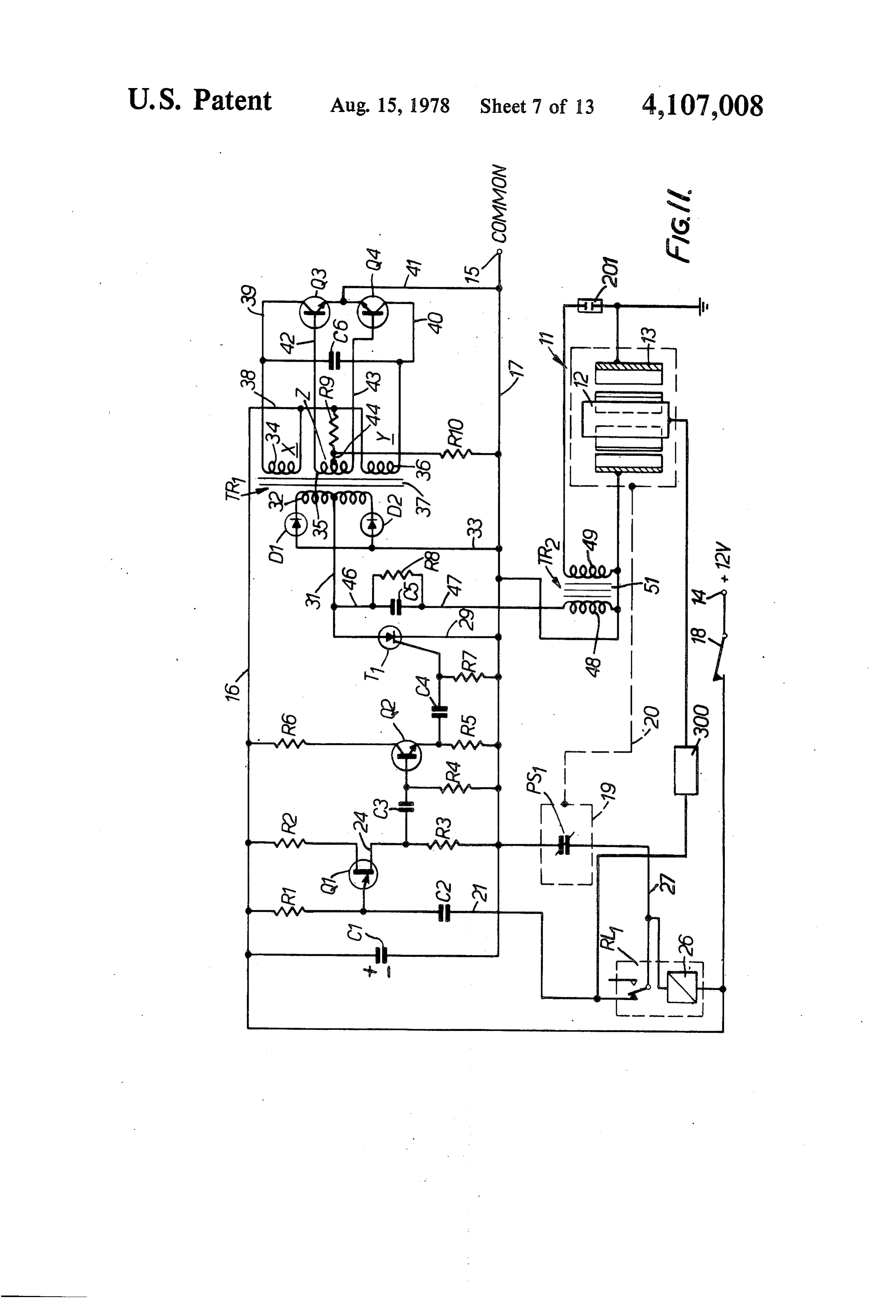
decomposition of the compounds concerned. For exam FIG. 9 is a cross-section on the line 9-9 in FIG. 8: ple, if water is irradiated with gamma radiation the FIG. 10 is a circuit diagram for the modified appara water will be dissociated into hydrogen and oxygen. 60 tus of FIGS. 8 and 9;
Danno proposes the use of a nuclear reactor as a source FIG. 11 is a circuit diagram for a further modified of radiation on a massive scale but concludes that water apparatus;
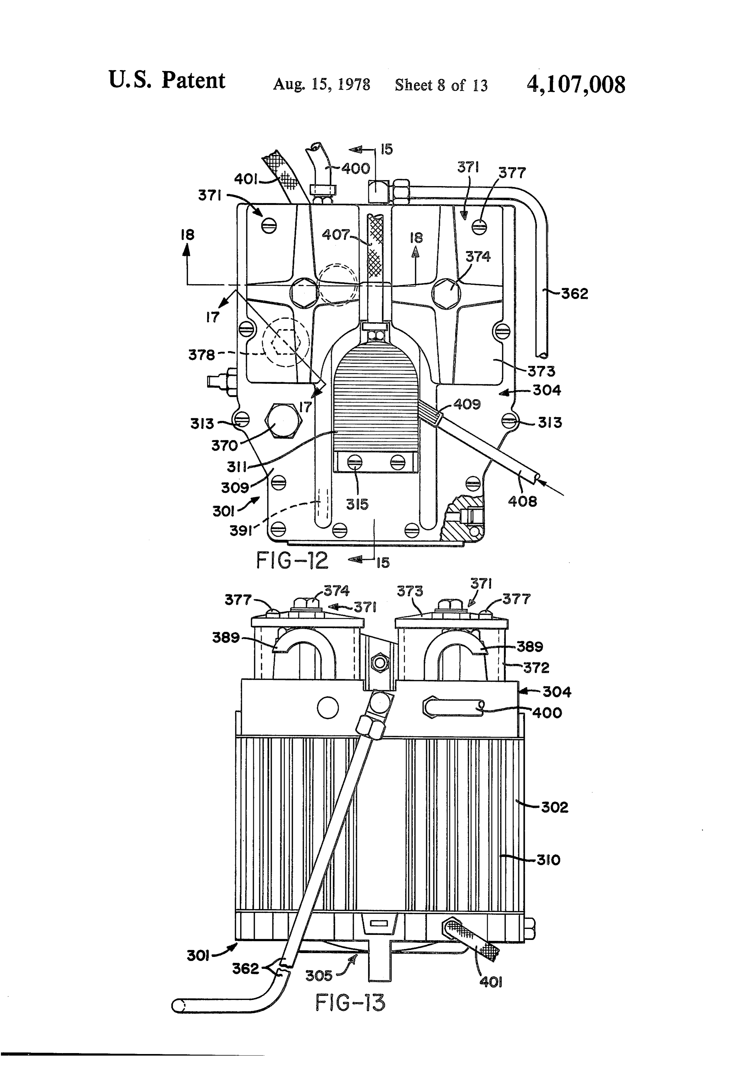
radiolysis is not a very efficient method of producing FIG. 12 is a plan view of an electrolytic cell of a hydrogen and he proposes instead a process involving a further embodiment of the invention;
radiolysis of carbon dioxide to produce carbon monox 65 FIG. 13 is a rear view of the cell illustrated in FIG. ide and oxygen and a subsequent conversion of the 12;
carbon monoxide to hydrogen gas by the conventional FIG. 14 is an underneath view of the cell illustrated in water/gas conversion process. FIG. 12;

Page 16
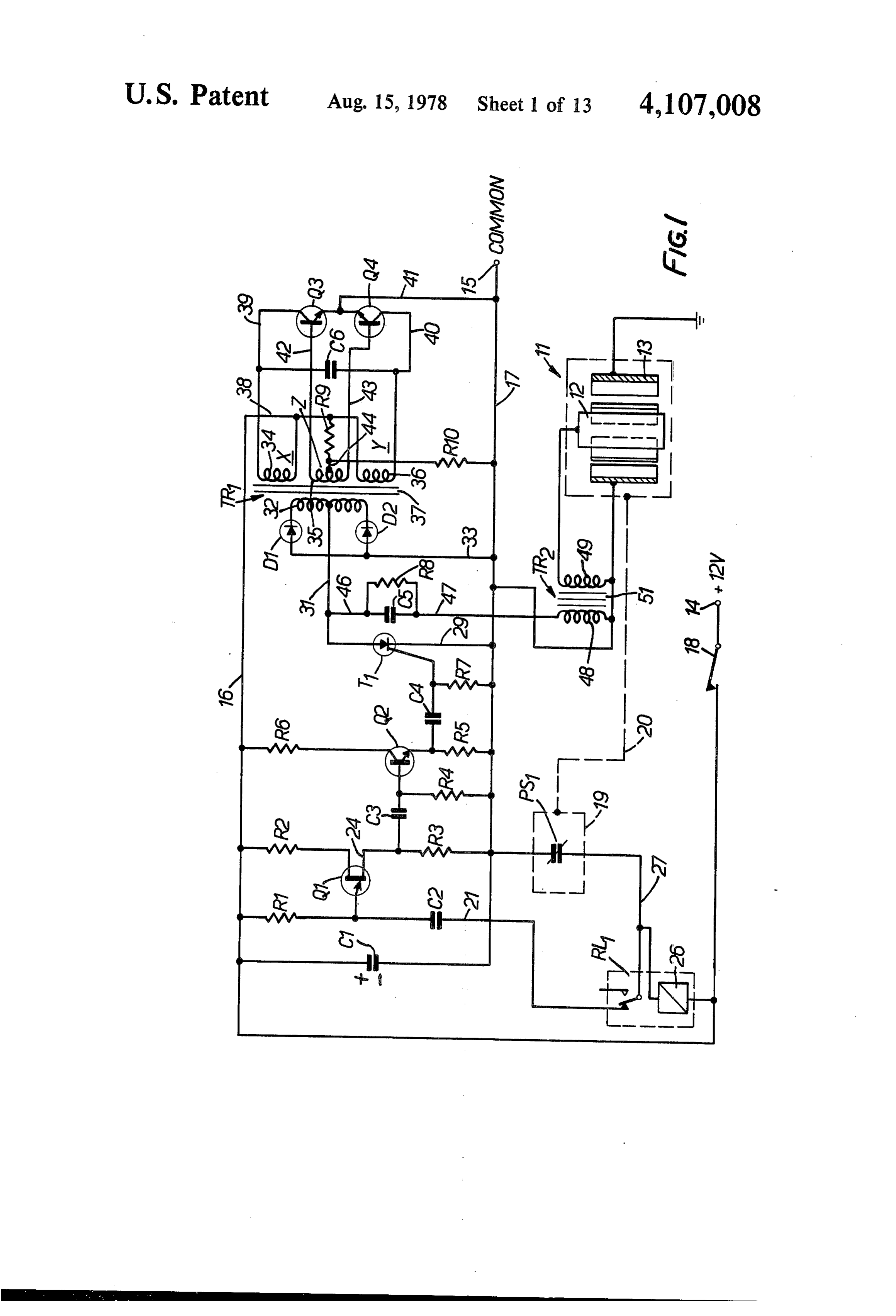
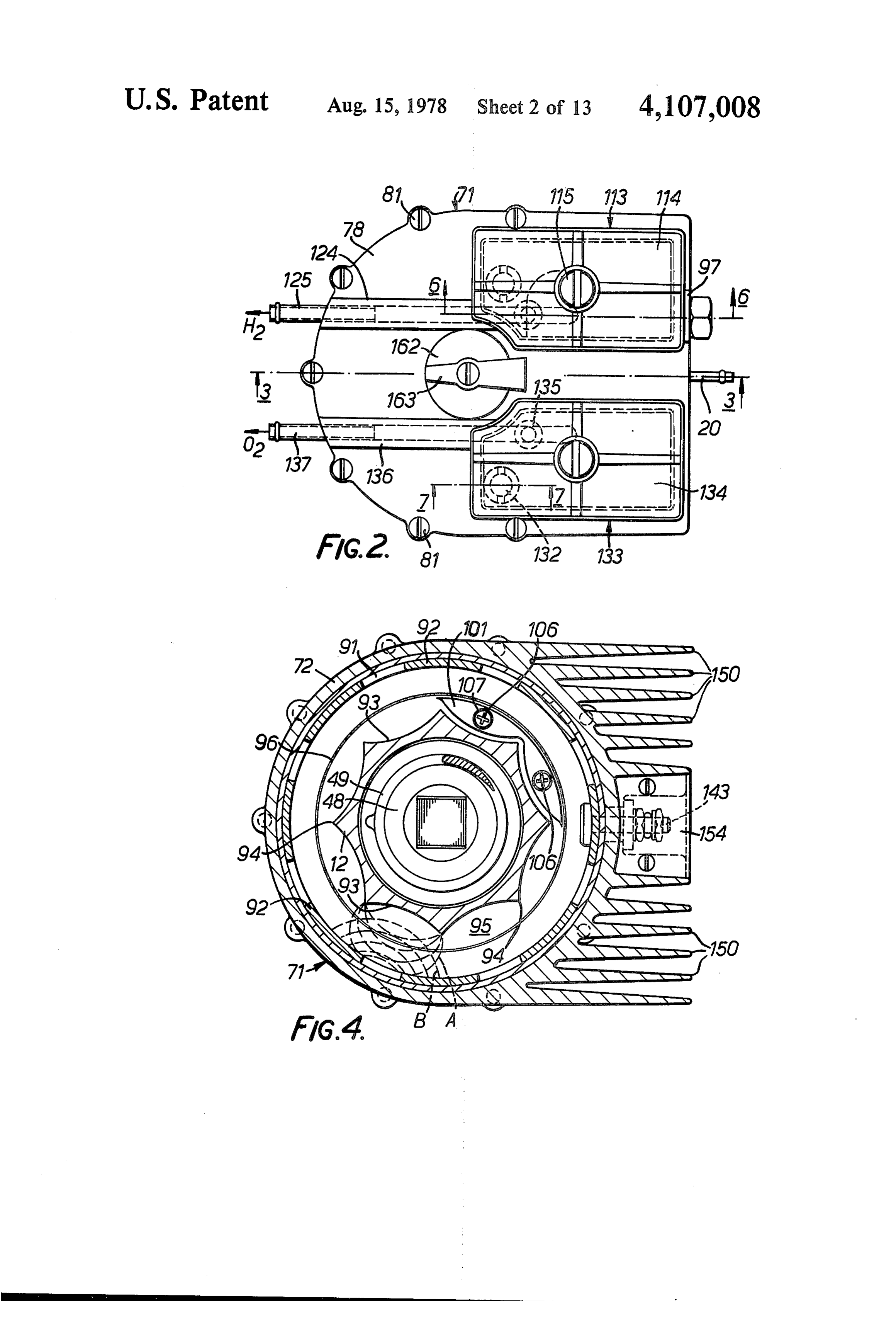
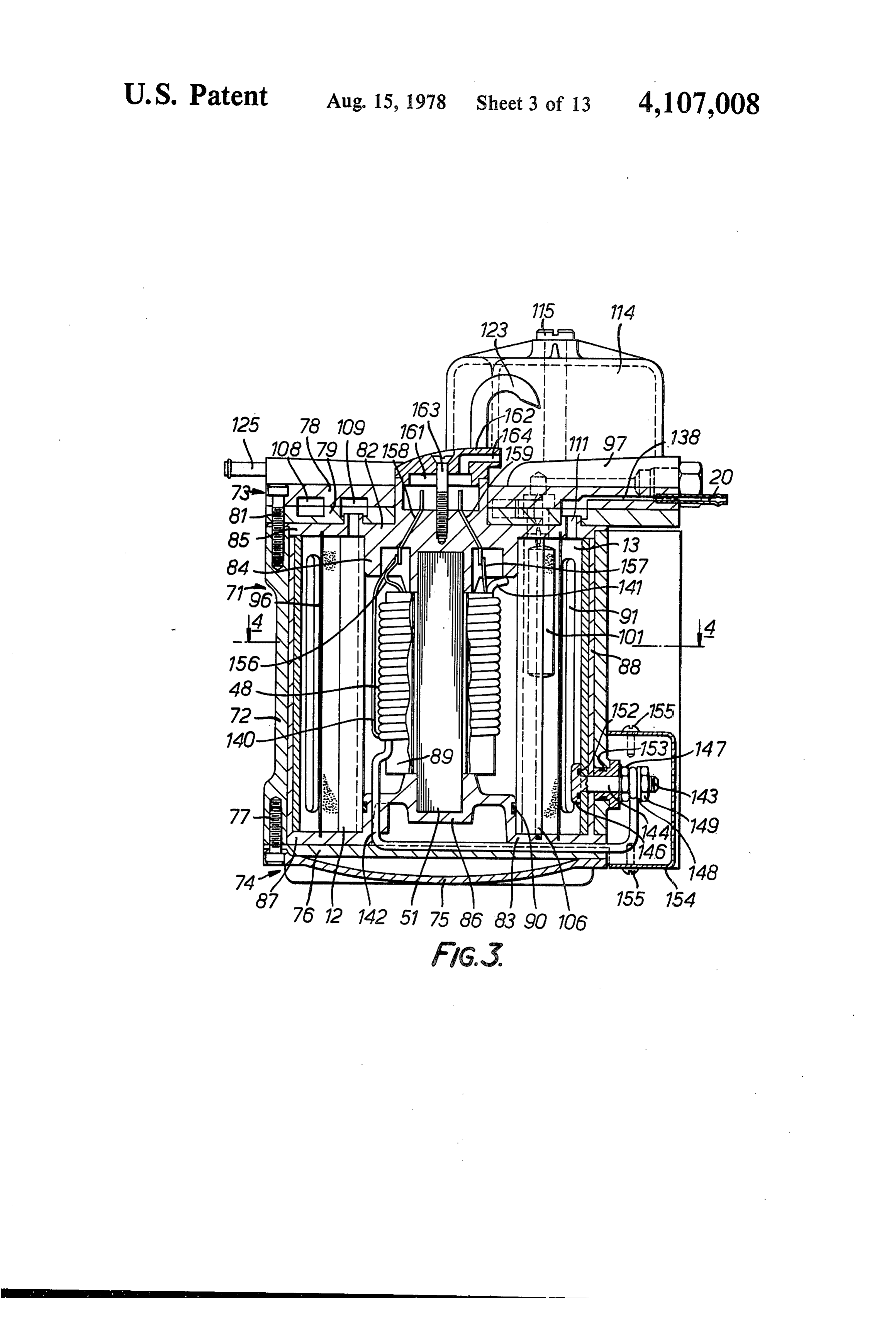
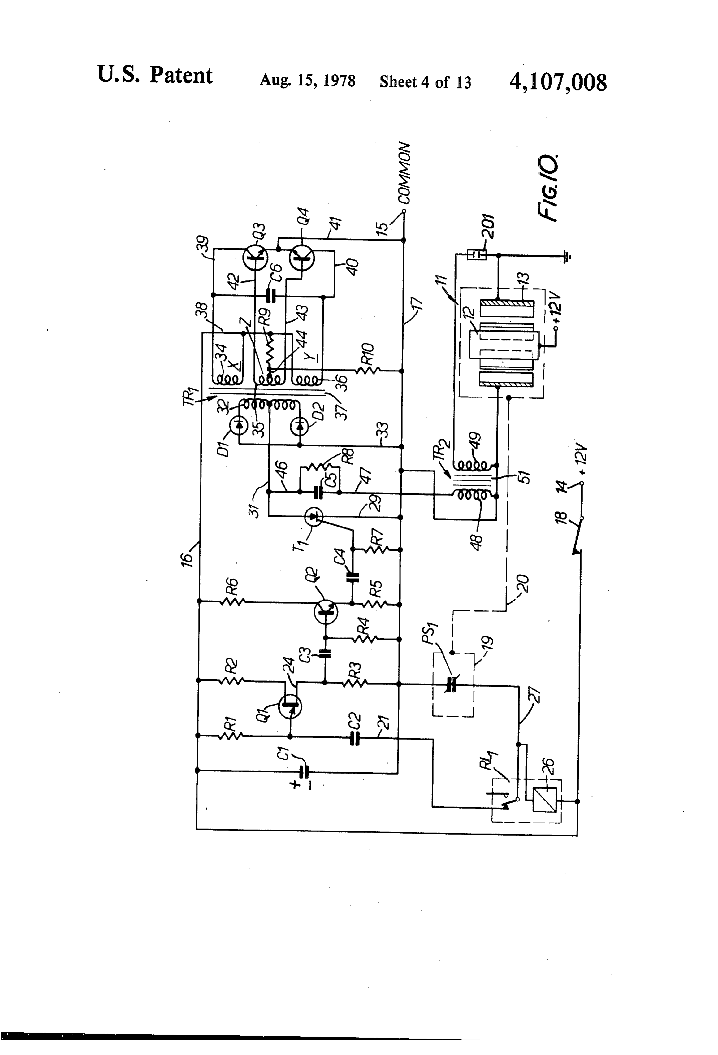
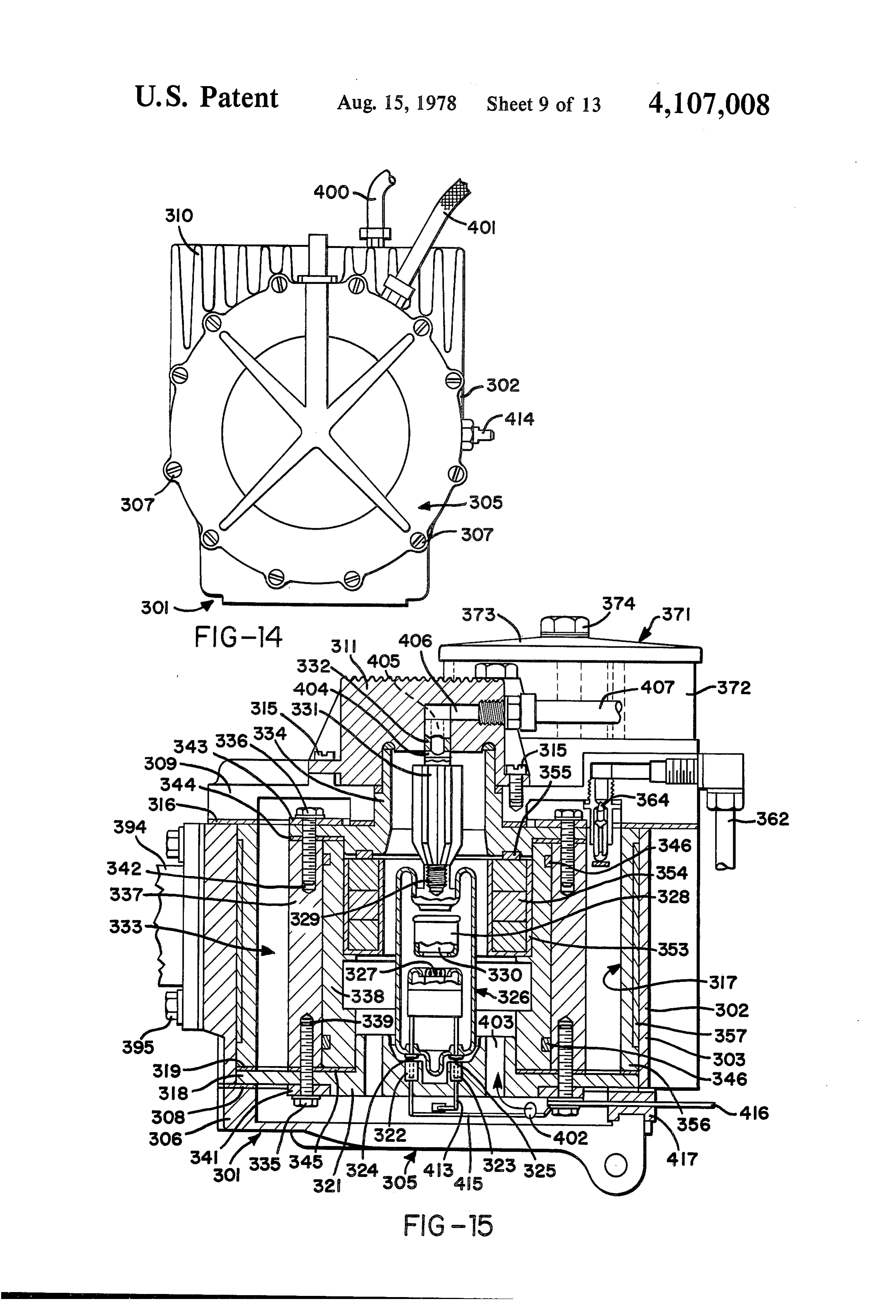
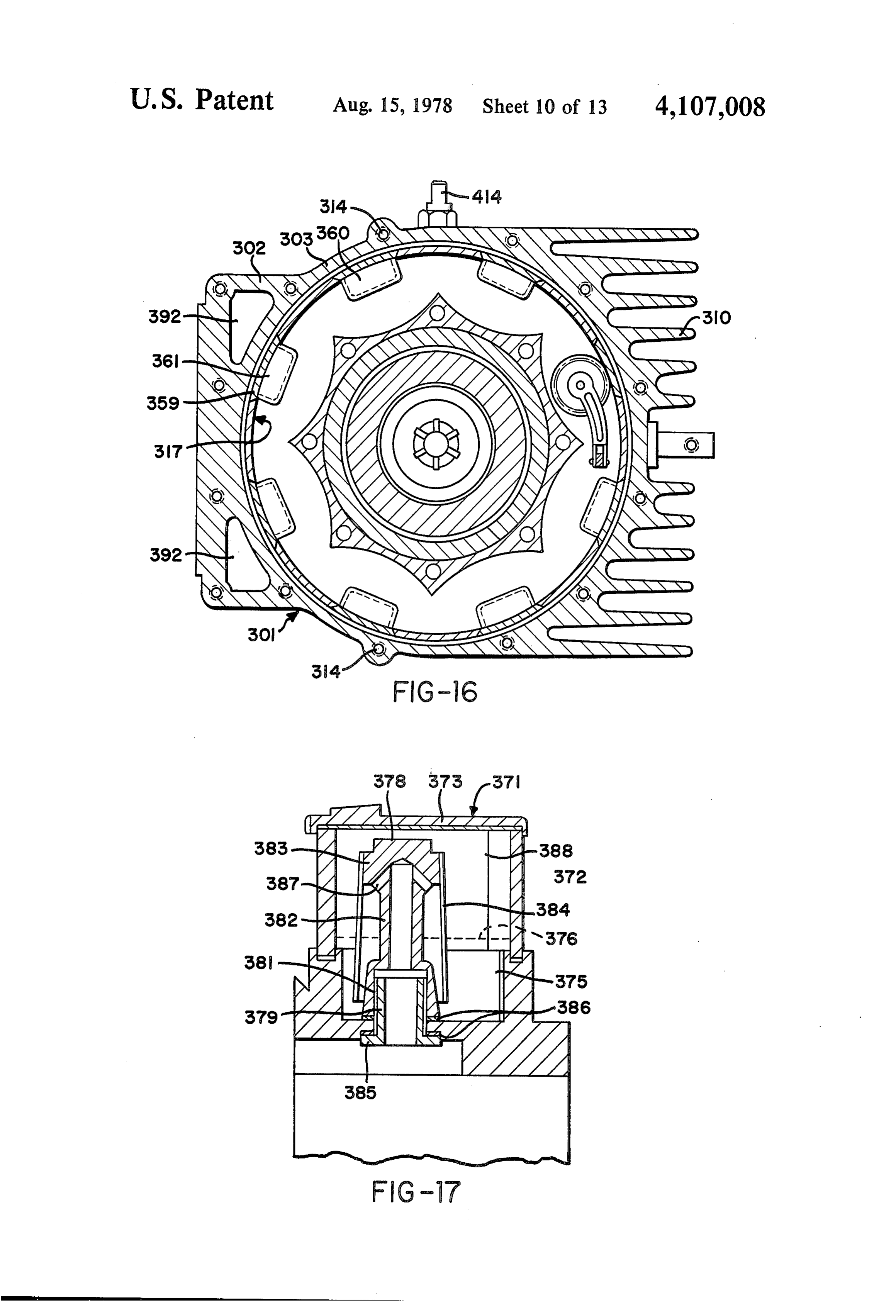
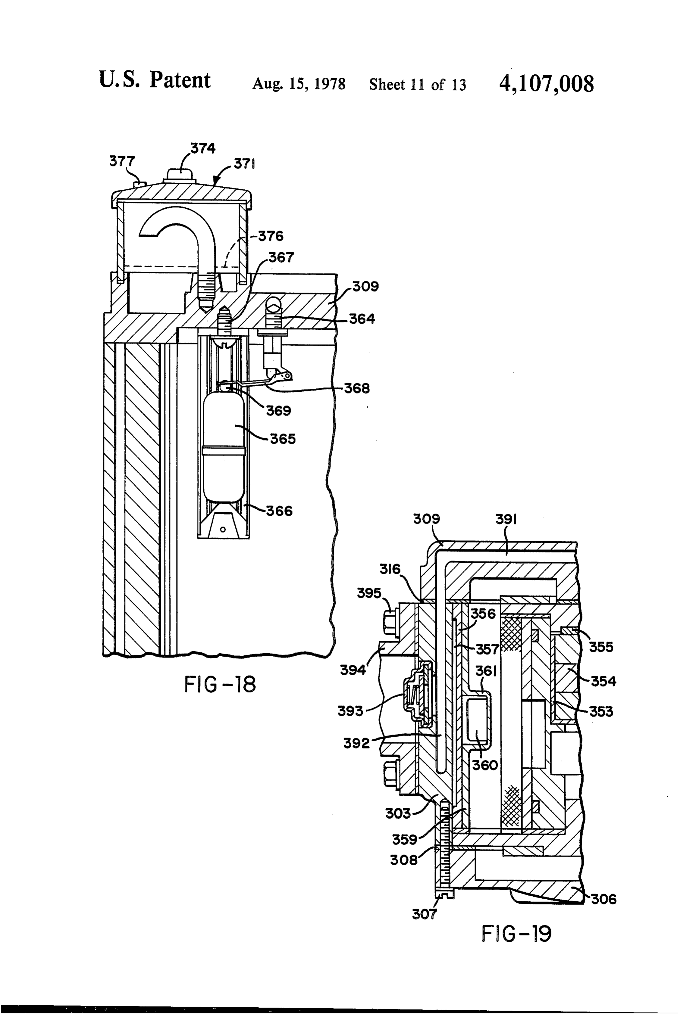
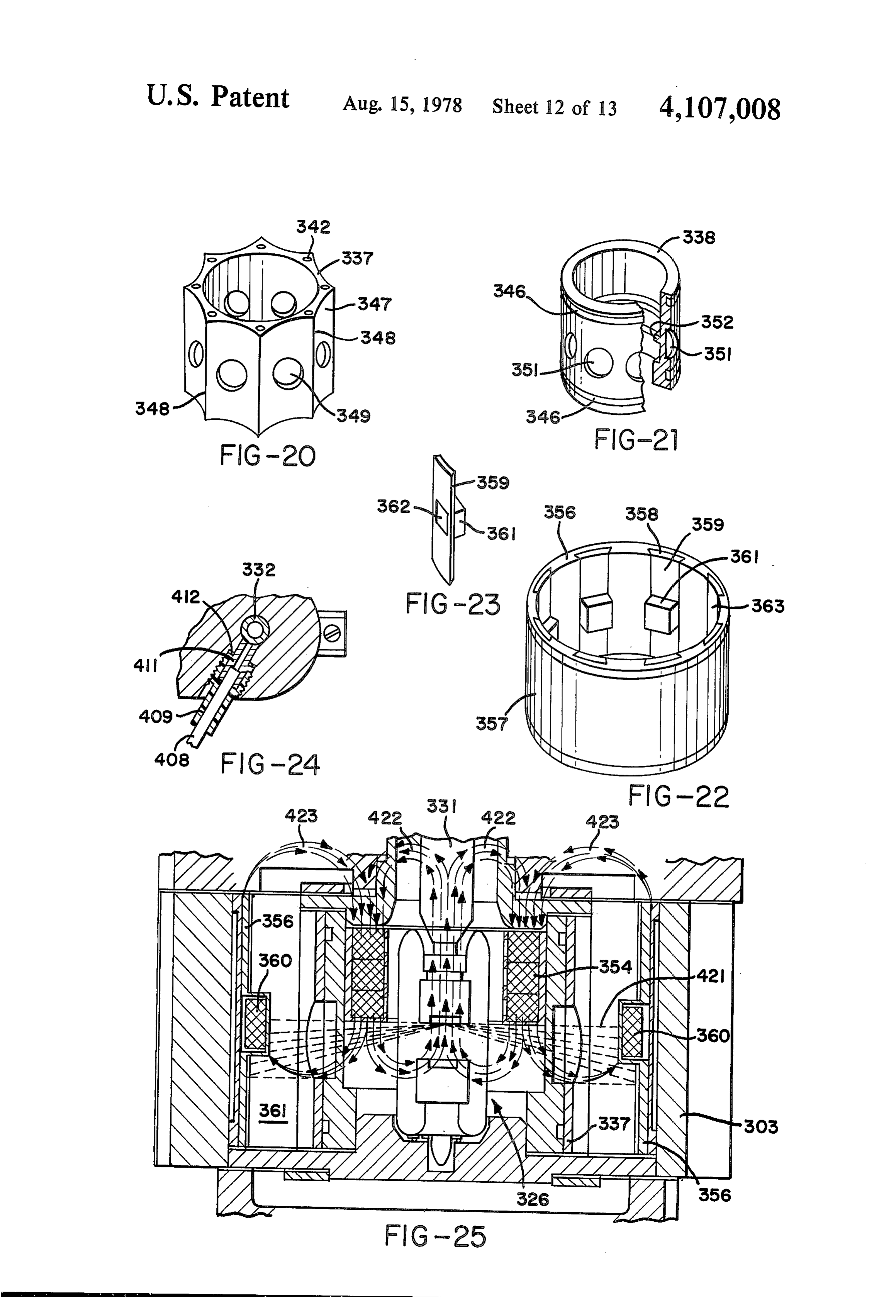
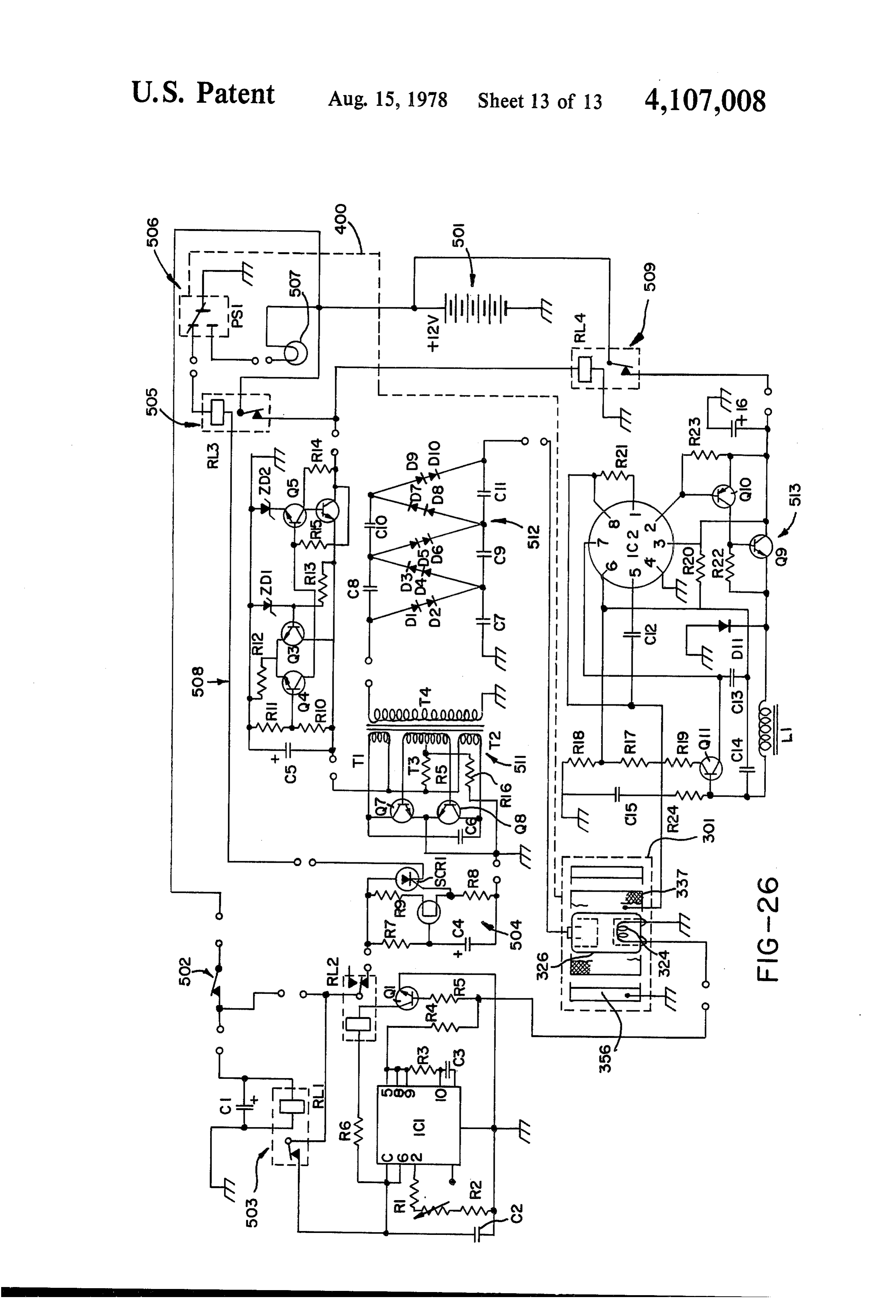
FIG. 15 is a vertical cross-section on the line 15-15 generation of triggering pulses to thyristor T1 until a in FIG. 12; required electrical condition has been achieved in the FIG. 16 is a horizontal cross-section through the cell transformer circuitry to be described below. It is pre of FIG. 12; ferred that relay RL1 be hermetically sealed and have a FIG. 17 is a cross-section on the line 17-17 in FIG. 5 balance armature so that it can operate in any position 12; and can withstand substantial shock or vibration. FIG. 18 is a cross-section on the line 18-18 in FIG. When the connection between capacitor C2 and line 12; 17 is made via relay RL1, uninjunction transistor Q1 FIG. 19 is a cross-section on the line 19-19 in FIG. will act as an oscillator to provide positive output pulses 12; 10 in line 24 at a pulse rate which is controlled by the ratio FIG. 20 is a perspective view of an anode component of R1:C1 and at a pulse strength determined by the ratio of the cell shown in FIG. 12; of R2:R3. These pulses will charge the capacitor C3. FIG. 21 is a broken perspective view of an anode Electrolytic capacitor C1 is connected directly between sleeve component of the cell shown in FIGS. 12; the common positive line 16 and the common negative FIG. 22 is a perspective view of a cathode assembly 15 line 17 to filter the circuitry from all static noise. of the cell shown in FIG. 12; Resistor R1 and capacitor C2 are chosen such that at FIG. 23 is a perspective view of a component of the the input to transistor Q1 the pulses will be of saw tooth assembly shown in FIG. 22; form. This will control the form of the pulses generated FIG. 24 is a scrap cross-section through an electrical in the subsequent circuitry, and the saw tooth pulse connection incorporated in the cell; 20 form is chosen since it is believed that it produces the FIG. 25 is a vertical cross-section through the cell most satisfactory operation of the pulsating circuitry. It illustrating diagrammatically paths of electromagnetic should be stressed, however, that other pulse forms, radiation and magnetic fields within the cell; and such as square wave pulses, could be used. Capacitor FIG. 26 is an electric circuit diagram for the appara C3, which is charged by the output pulses of transistor tus illustrated in FIGS. 12 to 25. 25 Q1, discharges through a resistor R4 to provide trigger DESCRIPTION OF THE PREFERRED ing signals for transistor Q2. Resistor R4 is connected to EMBODIMENTS the common negative line 17 to serve as a gate current limiting device for transistor Q2.
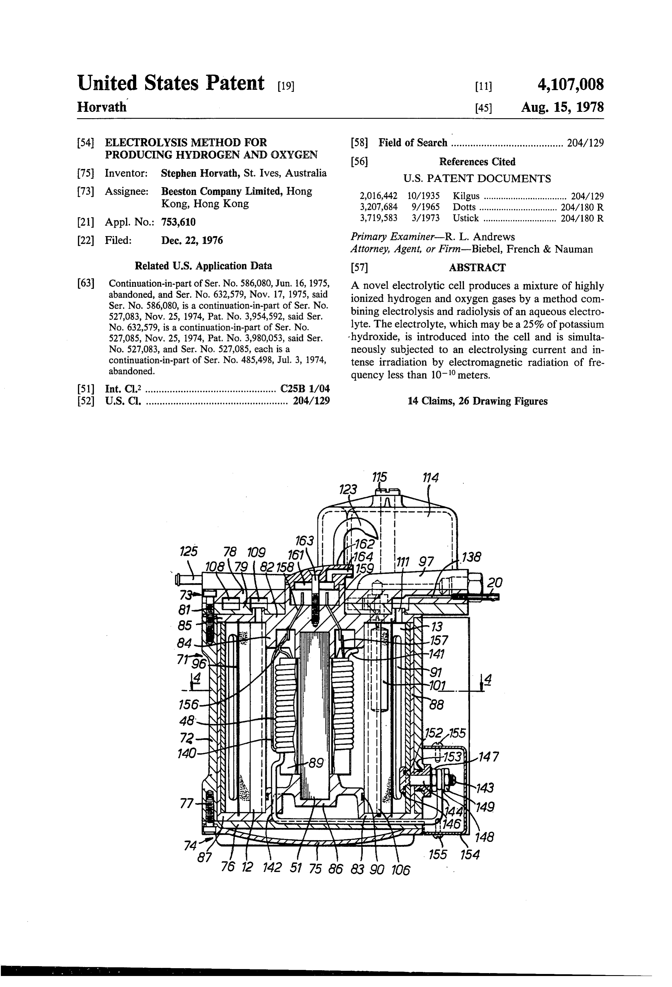
The apparatus illustrated in FIGS. 1 to 7 comprises The triggering signals produced by transistor Q2 via an electrolytic cell denoted generally as 11 and having 30 the network of capacitor C3 and resistor R4 will be in an anode 12 and cathode 13. The apparatus has an elec the form of positive pulses of sharply spiked form. The tric circuit such as to generate high voltage pulses of collector of transistor Q2 is connected to the positive electrical energy which are applied between the anode supply line 16 through resistor R6 while the emitter of 12 and the cathode 13. Specifically, the circuit is such as that transistor is connected to the common negative line to develop the required high voltage pulses from a 35 17 through resistor R5. These resistors R5 and R6 con source of direct current electrical energy which may for trol the strength of current pulses applied to a capacitor example be a 12 volt battery, connected between termi C4 which discharges through a resistor R7 to the com nals 14, 15. Line 16 from terminal 14 may be considered mon negative line 17, thereby to apply triggering signals as receiving the positive input and line 17 from terminal to the gate of thyristor T1. The gate of thyristor T1 15 may be considered as a common negative for the 40 receives a negative bias from the common negative line circuit. Line 16 includes a simple ON/OFF master con via resistor R7 which thus serves to prevent triggering trol switch 18. of the thyristor by the inrush currents. As shown in FIG. 1 the electrical circuit comprises The triggering pulses applied to the gate of thyristor pulse generator circuitry comprising unijunction tran T1 will be very sharp spikes occurring at the same sistor Q1 with associated resistors R1, R2, R3 and ca 45 frequency as the saw tooth wave form pulses estab pacitors C2 and C3. This circuity produces pulses lished by unijunction transistor Q1. It is preferred that which are used to trigger an NPN silicon power transis this frequency be of the order of 10,00 pulses per second tor Q2 which in turn provides via a capacitor C4 trig and details of specific circuit components which will gering pulses for a thyristor T1. achieve this result are listed below. Transistor Q2 serves Resistor R1 and a capacitor C1 are connected in 50 as an interface between unijunction transistor Q1 and series in a line 21 extending to one of the fixed contacts thyristor T1, preventing backflow of EMF from the of a relay RL1. The coil 26 of relay RL1 is connected gate of the thyristor, which might otherwise interfere between line 16 and a line 27 which extends from the with the operation of transistor Q1. Because of the high moving contact of the relay to the common negative voltages being handled by the thyristor and the high line 17 via a normally closed pressure operated switch 55 back EMF applied to transistor Q2, the latter transistor 19. The pressure control line 20 of switch 19 is con must be mounted on a heat sink.
nected in a manner to be described below to a gas col The cathode of thyristor T1 is connected via a line 29 lection chamber of electrolytic cell 11 in order to pro to the common negative line 17 and the anode is con vide a control connection whereby switch 19 is opened nected via a line 31 to the centre of the secondary coil when the gas in the collection chamber reaches a cer 60 32 of a first stage transformer TR1. The two ends of tain pressure. However, provided that switch 19 re transformer coil 32 are connected via diodes D1 and D2 mains closed, relay RL1 will operate when master con and a line 33 to the common negative line 17 to provide trol switch 18 is closed to provide a connection between full wave rectification of the transformer output. lines 21 and 27 thereby to connect capacitor C2 to the First stage transformer TR1 has three primary coils common negative line 17. The main purpose of relay 65 34, 35, 36 wound together with secondary coil 32 about RL1 is to provide a slight delay in this connection be a core 37. This transformer may be of conventional half tween the capacitor C2 and the common negative line 7 cup construction with a ferrite core. The secondary coil when the circuit is first energized. This will delay the may be wound on to a coil former disposed about the
Page 17
core and primary coils 34 and 36 may be wound in non-conductive. This permits charge to be built up bifilar fashion over the secondary coil. The other pri again in dump capacitor C5 for release when the thy mary coil 35 may then be wound over the coils 34, 36. ristor is next triggered by a signal from transistor Q2. Primary coils 34 and 36 are connected at one side by a Thus during each of the intervals when the thyristor is line 38 to the uniform positive potential of circuit line 16 and at their other sides by lines 39, 40 to the collectors inin primary its non-conducting state the rapidly alternating pulses coils 34, 36 of transformer TR1 produced by of transistors Q3, Q4. The emitters of transistors Q3, Q4 the continuously oscillating transistors Q3, Q4 produce, are connected permanently via a line 41 to the common via the transformer coupling, relatively high voltage negative line 17. A capacitor C6 is connected between output pulses which build up a high charge in capacitor lines 39, 40 to act as a filter preventing any potential 10 C5 and this charge is released difference between the collectors of transistors Q3, Q4. ristor is triggered. In a typicalsuddenly apparatus when the thy using the 12
The two ends of primary coil 35 are connected by volt DC supply at terminals 14,15 pulses of the order of lines 42, 43 to the bases of transistors Q3, Q4. This coil is centre tapped by a line 44 connected via resistor R9 to 22As amps at 300 volts may be produced in line 47. previously mentioned relay RL1 is provided in the positive line 16 and via resistor R10 to the common 15 the circuit to provide a delay in the connection of ca negative line 17.
When power is first applied to the circuit, transistors although verythe pacitor C2 to common negative line 17. This delay, short, is sufficient to enable transistors
Q3 and Q4 will be in their non-conducting states and Q3, Q4 to start oscillating to cause transformer TR1 to there will be no current in primary coils 34, 36. How ever, the positive current in line 16 will provide via 20 build up a charge in dumping capacitor C5 before the first triggering signal is applied to thyristor T1 to cause resistor R9 a triggering signal applied to the centre tap discharge of the capacitor. of coil 35, and this signal operates to trigger alternate The circuit includes a second stage transformer TR2. high frequency oscillation of transistors Q3, Q4, which will result in rapid alternating pulses in primary coils This is step-up transformer comprising a primary coil 48 and a secondary coil 49 wound about a common core 51 34,36. The triggering signal applied to the centre tap of 25 and it produces pulses of very high voltage in the sec coil 35 is controlled by the resistor network provided by ondary coil 49 which pulses are applied between anode resistors R9 and R10 such that its magnitude is not 12 and cathode 13. As shown in FIG. 1, the secondary sufficient to enable it to trigger Q3 and Q4 simulta coil 49 is connected not only between the anode and the neously but is sufficient to trigger one of those transis cathode but also back to the negative side of primary tors. Therefore only one of the transistors is fired by the 30 coil 48. The second stage transformer is built into the initial triggering signal to cause a current to flow anode of the electrolytic cell 11. Its physical construc through the respective primary coil 34 or 36. The signal tion and the manner in which its electrical connections required to hold the transistor in the conducting state is much less than that required to trigger it initially, so that areInmade a will be explained in detail below.
typical apparatus the output from the first stage when the transistor becomes conductive, some of the 35 transformer TR1 would be 300 volt pulses of the order signal applied to the centre tap of coil 33 will be di of 22 amps at 10,000 verted to the non-conducting transistor to trigger it. slightly les than 0.1.pulses per second at a duty cycle of This can be achieved from a uni
When the second transistor is thus fired to become form 12 volt and 40 amps DC supply applied between conductive, current will flow through the other of the terminals 14,15 using the following circuit components: primary coils 34.36 and since the emitters of the two 40 R1 2.7 Kohms watt 2% resistor transistors are directly connected together, the positive R2 220 ohms watt 2% resistor output of the second transistor will cause the first-fired R3 100 ohms watt 2% resistor transistor to be shut off. When the current drawn by the R4 22 K ohms watt 2% resistor collector of the secondfired resistor drops, part of the R5 100 ohms watt 2% resistor signal on the centre tap of coil 35 is diverted back to the 45 R6 200 ohms watt 2% resistor collector of the first transistor which is re-fired. It will R7 1 K ohms watt 2% resistor be seen that the cycle will then repeat indefinitely, so R8 10 Mohms 1 watt 5% resistor that transistors Q3, Q4 are alternately fired and shut off R9 100 ohms 5 watt 10% resistor in very rapid sequence. Thus current pulses flow in R105.6 ohms 1 watt 5% resistor alternate sequence through primary coils 34, 36 at a 50 2200 MF 16V electrolytic capacitor very high frequency, this frequency being constant and C1 C2 0.10 MF 10OV 10% capacitor independent of changes in input voltage to the circuit. C3
The rapidly alternating pulses in primary coils 34 and C412.2MF MF 100V 10% capacitor 100V 10% capacitor 36, which will continue for so long as master control C5 1 MF 1000V Ducon paper capacitor 5 S10A switch 18 remains closed, will generate higher voltage 55 C6 0.022 MF 160V capacitor signals at the same frequency in the transformer second Q1 - 2N 2647 PN unijunction transistor ary coil 32. Q2 2N 3055 NPN silicon power transistor A dump capacitor C5 bridged by a resistor R8 is Q3 2N 3055 NPN silicon power transistor connected by a line 46 to the line 31 from the secondary Q4 2N 3055 NPN coil of transformer TR1 and provides the output from 60 T1 BTW 30 800RMsilicon fast power transistor turn-off thyristor that transformer which is fed via line 47 to a second D1. A 14 P diode stage transformer TR2. D2. A 14 P diode
When thyristor T is triggered to become conductive RL1 PW5LShermetically sealed relay the full charge of dump capacitor C5 is released to PS1 P658A-10051 pressure switch second stage transformer TR2. At the same time the 65 TR1 Half-cup transformer cores 36/22-341 first stage of transformer TR1 ceases to function be Coil former 4322-021-30390 wound to provide a turns cause of this momentary short circuit placed across it ratio between secondary and primary of 18:1 and consequently thyristor T1 releases, i.e. becomes Secondary coil 32 = 380 turns
Page 18
Primary coil 34 = 9 turns fined between the flutes. The eight anode crests 94 are Primary coil 36 = 9 turns radially aligned centrally of the cathode strips 92, and Primary coil 35 = 4 turns the perimeter of the anode measured along its external Transistors Q2, Q3 and Q4 each need to be mounted surface is equal to the combined widths of the cathode on a heat sink and a suitable heat sink for this purpose is strips measured at the internal surfaces of these strips, so 35D3CB. The other circuit components may be in that over the major part of their lengths the anode and stalled in a steel container and the heat sink mounted cathode have equal effective areas. This equalisation of transistors fitted to an exterior surface of the steel con areas generally has not been available in prior art cylin tainer. Alternatively it would be possible to mount at drical anode/cathode arrangements. least transistor Q2 within the box if an appropriate heat 10 The annular space 95between the anode and cathode sink with extended surface area is provided within the serves as the electrolyte solution chamber. This cham box. ber is divided by a tubular membrane 96 made of nickel The physical construction of electrolytic cell 11 and film of no more than 0.015 inch thickness perforated by the second stage transformer TR2 is illustrated in FIGS. holes of no more than 0.004 inch diameter of 5000 perfo 2 to 7. The cell comprises an outer casing 71 having a 15 rations per square inch. This perforated membrane tubular peripheral wall 72 and top and bottom closures serves as a barrier against mixing of hydrogen and oxy 73, 74. Botton closure 74 is comprised of a domed cover gen generated at the cathode and anode respectively 75 and an electrically insulating disc 76 which are held while permitting the electrolytic flow of current be to the bottom of peripheral wall 72 by circumferentially tween the electrodes. Its ends fit into annular slots in the spaced clamping studs 77. Top closure 73 is comprised 20 peripheral flanges of upper and lower insulators 82,83 of a pair of top plates 78,79 disposed face-to-face and whereby it is electrically isolated from all other compo held by circumferentially spaced clamping studs 81 nents of the cell. This barrier may alternatively be screwed into tapped holes in the upper end of periph formed by a tightly stretched web of nylon mesh mate eral wall 72. rial of sufficiently small mesh size, i.e. such that the The anode 12 of the cell is of generally tubular forma 25 mesh openings will not pass bubbles of greater than tion. It is disposed vertically within the outer casing and 0.004 inch diameter. The mesh material may be is clamped between upper and lower insulators 82.83. stretched between end rings of a plastic holder fitted Upper insulator 82 has a central boss portion 84 and an between the annular slots in insulators 82,83. annular peripheral flange portion 85, the outer rim of Initially chamber 95 is filled approximately 75% full which is clamped between upper closure plate 79 and 30 with an electrolyte solution of 25% potassium hydrox the upper end of peripheral wall 72. Lower insulator 83 ide in distilled water. Thereafter, as the reaction pro has a central boss portion 86, an annular flange portion gresses, the water is depleted and is made up with fresh 87 surrounding the boss portion and an outer tubular water admitted into the outer section of chamber 95 via portion 88 standing up from the outer margin of flange an inlet nozzle 97 formed in upper closure plate 78. The portion 87. Insulators 82,83 are moulded from an elec 35 electrolyte solution passes from the outer to the inner trically insulating material which is also alkali resistant. section of chamber 95 via the holes in membrane 96. It Polytetrafluoroethylene is one suitable material. will be noted however, that membrane 96 is perforated When held together by the upper and lower closures, only below the level of the electrolyte solution so that insulators 82,83 form an enclosure within which anode there may be no mixing of hydrogen and oxygen within 12 and the second stage transformers TR2 are disposed. 40 the cell. The holes, while large enough to allow passage Anode 12 is of generally tubular formation and it is of electrolyte solution therethrough are small enough to simply clamped between insulators 82, 83 with its cylin prevent passage of bubbles of hydrogen and oxygen drical inner periphery located on the boss portions 84, normally occurring in the reaction. In the case where 86 of those insulators. It forms a transformer chamber the gas barrier is formed by nylon mesh the upper ring which is closed by the boss portions of the two insula 45 of the holder would be formed to provide a solid barrier tors and which is filled with a suitable transformer oil. above the level of the electrolyte solution. An O-ring seal 90 is fitted between insulator boss 86 and Nozzle 97 has a flow passage 98 extending to an elec the anode to prevent loss of oil from the transformer trolyte inlet valve 99 controlled by a float 101 in cham chamber. ber 95. Valve 99 comprises a bushing 102 mounted The transformer core 51 is formed as a laminated mild 50 within an opening extending downwardly through steel bar of approximately 3 inch square section. It ex upper closure plate 78 and the peripheral flange 85 of tends vertically between the insulator boss portions upper insulator 82 and providing a valve seat which 8486 and its ends are located within recesses in those cooperates with valve needle 103. Needle 103 is lightly boss portions. The secondary transformer winding 49 is biased upwardly by a spring 104 within valve bushing wound directly onto core 59 whereas the primary wind 55 102. However, the pressure of electrolyte solution ing 48 is wound on a tubular former 89 so as to be within nozzle 97 is sufficient to push the needle down spaced outwardly from the secondary winding within wardly against this spring to allow admission of electro the oil filled transformer chamber. lyte solution to chamber 95 until float 101 lifts the nee The cathode 13 is in the form of a logitudinally slot dle hard against the valve seat. The float slides verti ted tube which is a close fit within the outer tubular 60 cally on a pair of star-section slide rods 106 extending portion 88 of insulator 83. It has eight equally spaced between the upper and lower insulators 82 and 83 and longitudinal slots 91, so that it is essentially comprisedalso formed of polytetrafluoroethylene. These rods of eight cathodestrips 92 disposed between the slots and extend through appropriate holes 107 through the float. connected together at top and bottom only. The depth offloat 101 is chosen such that the electro Both the anode and cathode are made of solid nickel. 65 lyte solution fills only approximately 75% of the cham The outer periphery of the anode is machined to form ber 95, leaving the upper part of the chamber as a gas eight circumferentially spaced flutes 93 which have space which can accommodate expansion of the gener arcuate roots meeting at sharp crests or ridges 94 de ated gas due to heating within the cell.
Page 19
As electrolysis of the electrolyte solution within thus possible for example, to feed the hydrogen and chamber 95 proceeds, hydrogen gas is produced at the oxygen gases directly to an internal combustion engine cathode, and oxygen gas is produced at the anode. without intermediate storage, and the apparatus will These gases bubble upwardly into the upper part of produce the gases according to demand. The stiffness of chamber 95 where they remain separated in the inner 5 the control springs for gas escape valves 112,132 must and outer compartments defined by membrane 96, and of course be chosen to allow escape of the hydrogen it should be noted that the electrolyte solution enters and oxygen in the proportions in which they are pro that part of the chamber which is filled with oxygen duced by electrolysis, i.e. in the ratios 2:1 by volume. rather than hydrogen so there is no chance of leakage of Reservoirs 113,133 are provided as a safety precau hydrogen back throgh electrolyte inlet nozzle 97. 10 tion. If a sudden back-pressure were developed in the The abutting faces of upper closure plates 78,79 have matching annular grooves forming within the upper delivery pipes this could only shatter the plastic hous ings 114,134 and could not be transmitted back into the closure inner and outer gas collection passages 108,109. electrolytic cell. Switch 19 would then operate to stop Outer passage 108 is circular, and it communicates with further generation of gases within the cell. the hydrogen compartment of chamber 95 via eight 15 The electrical connections of secondary transformer ports 111 extending downwardly through top closure TR2 are shown in FIG. 3. The two ends of the primary plate 79 and the peripheral flange of upper insulator 82 transformer coil 48 are connected by wires 156,157 to adjacent the cathode strips 92. Hydrogen gas flows conductors 158,159 which extend upwardly through upwardly through ports 111 into passage 108 and the central boss portion of upper insulator 83. The thence upwardly through a one-way valve 112 (FIG. 7) 20 upper ends of conductors 158,159 project upwardly as into a reservoir 113 provided by a plastic housing 114 pins within a socket 61 formed in the top of upper insu bolted to top closure plate 79 by a centre stud 115 and lator 83. The top of socket 161 is closed by a cover 162 sealed by a gasket 116. The lower part of housing 114 is which charged with water 117, and the hydrogen passes in throughis which held by a centre stud 163 and has a passage 164 wires from the external circuit may be wardly into reservoir 113 via a tube 118. Valve 112 25 extended and connected to conductors 158,159 by any comprises a bushing 119 providing a valve seat for suitable connector (not shown) located within socket valve stem 121 which is biased downwardly by a spring 16.
122 and also by the weight of water acting on it. The ends of secondary coil 49 are connected between Hydrogen is withdrawn from reservoir 113 via a the anode and the cathode and an additional connection crooked tube 123 which connects with an outlet passage 30 124 in top closure plate 78. Outlet passage 124 termi issidemade to the conductor 158 connected to the negative of the primary coil. Specifically, one end of coil 49 nates in a hydrogen delivery nozzle 125 which may deliver the hydrogen either to storage or directly to the isbeing connected to the anode by a wire 141, this connection entirely within the anode. The other end of coil point of consumption. 49 is connected to the cathode Wia a wire 142 which Oxygen is withdrawn from chamber 95 via the inner 35 extends downwardly through a hole in the bottom insu annular passage 109 in the top closure. Passage 109 is lator 83 and then horizontally to leave casing 71 be not circular but has a scalloped configuration to extend around the electrolyte inlet. Oxygen enters it through tween bottom insulating disc 76 and insulator 83. The upper face of disc 76 and the lower face of insulator 83 seven ports 131 extended through top closure plate 79 are grooved to receive and clamp onto wire 142. Out and the annular flange portion of upper insulator 82. 40 side the casing, wire 142 is connected to a cathode The oxygen flows upwardly from passage 109 through terminal bolt 143. Terminal bolt 143 has a stem 144 a one-way valve 132 and into a reservoir provided by a extending through an opening in the cathode and an plastic housing 134. The arrangement is similar to that insulating bush 144 fitted in an aligned opening in the for withdrawal of hydrogen and will not be described in casing wall 72. The head 146 of the thermal bolt is great detail. Suffice to say that the bottom of the cham- 45 drawn against the inner periphery of the cathode by ber is charged with water and the oxygen is withdrawn tightening of a clamping nut 147, and the end of wire through a crooked tube 135 and an outlet passage 136 in 142 has an eye which is clamped between nut 147 and a top closure plate 78 terminating in an oxygen delivery washer 148 by tightening a terminal end nut 149. A nozzle 137. washer 151 is provided between nut 147 and bush 144, The pressure sensing tube 20 of control switch 19 is 50 and sealing O-rings 152,153 are provided between bolt connected directly to the upper part of chamber 95 via head 146 and the cathode and between bush 144 and passage 138 in top closure plate 79 and upper insulator casing wall 72 to prevent escape of electrolyte solution. 82 to sense the hydrogen pressure within the upper part The terminal connection is covered by a housing 154 of this chamber. If this pressure rises above a predeter held in place by fixing screws 155. mined level switch 19 operates to disconnect capacitor 55 The additional electrical connection between coil 49 C2 from the common negative line 17. This removes the negative signal from capacitor C2 which is necessary to and conductor 158 is made by a wire 150 connected between the wire 142 and the wire 156.
maintain continuous operation of the pulse generating circuitry for generating the triggering pulses on thy 22Assuming an input to secondary transformer TR2 of ristor T1 and these triggering pulses therefore cease. 60 voltage appliedvolts amps at 300 and a coil ratio of 100:1 the output between the anode and cathode would
The transformer TR1 continues to remain in operation then be 30,000 volts at a pulse rate of 10,000 pulses per to charge dumping capacitor C5, but because thyristor
T1 cannot be triggered, dumping capacitor C5 will second, with a current flow of 220 milliamps. This output produces a discharge between the anode simply remain charged until the hydrogen pressure in and the electrolyte which results in the production of chamber 95 falls below the predetermined level and 65 short wave length electromagnetic radiation and also a triggering pulses are applied once more to thyristor T1. pulsating current within the electrolyte. Within the Pressure switch 19 thus controls the rate of gas produc space between the anode and the cathode there is a tion according to the rate at which it is withdrawn. It is pulsating magnetic field due to the secondary coil of the
Page 20
transformer and this assists in the generation of the short tooth wave input and sharply spiked output pulses of wave length radiation. Specifically, radiation of wave the preferred oscillator circuit the duty cycle of the length 100 meters to 10-meters is produced and this pulses produced at a frequency of 10,000 pulses per radiation produces radiolysis of the electrolyte while second was about 0.006. This pulse form helps to mini the electrolytic flow of current provides for release of 5 mise overheating problems in the components of the the decomposition products of hydrolysis. oscillator circuit at the high pulse rates involved. A The configuration of the anode and the cathode and duty cycle of up to about 0.1, as may result from a the arrangement of the secondary transformer within square wave input, would be feasible but at a pulse rate the central anode is of great importance. The anode and of 10,000 pulses per second, some of the components of cathode, being constructed of magnetic material, are 10 the oscillator circuit would then be required to with acted on by the magnetic field of the transformer TR2 stand unusually high heat inputs. A duty cycle of about to become, during the period of energization of that 0.005 would be a minimum which could be obtained transformer, strong conductors of magnetic flux to cre with the illustrated type of oscillator circuitry. ate a strong magnetic field in the inter-electrode space The illustrated electrolytic cell 11 is designed to pro between the anode and the cathode. Moreover, the 15 duce hydrogen and oxygen at a rate sufficient for opera fluted external periphery of the anode and the strip tion of internal combustion engines and other uses formation of the cathode, shapes this magnetic field known in the art. Typically, it may have a diameter of such that field lines from the anode are caused to inter about 8 inches and a height of about 8 inches, so that it sect field lines from the cathode as indicated by the will be seen to be extremely compact. respective sets of dotted lines A and B drawn in one 20 A modified apparatus constructed in accordance with portion of the electrolyte chamber in FIG. 4. The high the invention is illustrated in FIGS. 8 to 10. this appara speed photons of the short wave electro-magnetic radia tus is largely the same as that already described with tion will tend to follow these field lines. Moreover, the reference to FIGS. 1 to 7 and common components hydrogen and oxygen ions in the electrolyte will be have been identified by the same reference numerals. In concentrated along these field lines and will, in fact, 25 this case however the output of the secondary trans move along them. Thus, the statistical possibility of former TR2 is not applied directly between the anode collision between the high speed photons of the short 12 and the cathode 13, but is instead applied to radiation wave length radiation and the ions in the electrolyte is generators denoted generally as 201 mounted in the very much improved by the generation of this particu lower part of the electrolytic cell and in addition a lar magnetic field. Moreover, there is a greatly in 30 constant DC potential, for example 12 volts, is applied creased possibility of collision between the ions them between the anode and cathode as indicated in FIG. 10. selves since these will tend to collide at the intersections Modifications made to the bottom part of the electro of the field lines A and B with subsequent improved lytic cell involve a thickening of the central boss por liberation of hydrogen and oxygen gases. Thus, the tion of lower insulator 83. The thickened boss portion is configuration of the anode and cathode which produces 35 indicated at 86A. The insulating disc 76 of the previous intersecting magnetic field lines is extremely important apparatus is eliminated and the lower domed cover as in improving the efficiency of the radiolysis process and modified and is indicated in FIGS. 8 and 9 as 75A. The also in liberating the decomposition products of hydro modification of cover 75A includes the provision of a gen and oxygen. This particular configuration also peripheral upstanding sill 202 and the cover is fastened causes the surface area of the anode to be extended and to the bottom of outer casing 71 by long clamping studs permits an arrangement in which the anode and cathode 77A extending through vertical holes in the sill 202. have equal surface areas which is most desirable in Radiation generators 201 are disposed directly be order to minimize electrical losses. It is also desirable neath the annular electrolyte chamber at diametrically that the anode and cathode surfaces at which gas is opposite sides of the chamber. They are of identical produced be roughened, for example, by sand blasting 45 construction, each comprising a cylindrical ceramic or knurling. This promotes separation of the gas bubbles holder 203 which has a central bore to receive tungsten from the electrode surfaces and avoids the possibility of rod electrodes 204,205. These electrodes are disposed overvoltages. The anode and cathode may both be with a gap between them and the holder has an upper made of nickel but this is not essential, and they might notch 210 which exposes the electrode gap. The outer alternatively be formed of nickel plated steel, or they 50 end of electrode 205 has a domed head 206 and a spring could be made of platinum or be platinum plated. 207 is compressed between head 206 and the outer end The heat generated by transformer TR2 is conducted of a hollow stud 208 which screws into a tapped open via the anode to the electrolyte solution and also in ing extended radially through sill 202 of cover 75A. The creases the mobility of the ions within the electrolyte inner end of electrode 205 is sharply pointed and the solution and thus also contributes to the progress of 55 pointed tip is spaced apart from the adjacent flat end of electrolysis and radiolysis. If desired for dissipation of electrode 204 by a gap of at least 0.006 inches and pref. heat there may be provided cooling fins such as fins 150. erably about 0.016 inches. Electrode 204 is shaped as a The location of the transformer within the anode also simple cylindrical tungsten rod fitted with a brass inner enables the connections of the second coil 49 to the end cap 209 which has a tongue 211 engaging a slot 212 anode and cathode to be made of short, well protected 60 in the end of a brass rod 213 mounted in a hole bored conductors. diametrically through the thickened boss 86A of insula Dumping capacitor C5 will determine a ratio of tor 83.
charging time to discharge time which will be largely The output of secondary transformer coil 49 is ap independent of the pulse rate. The pulse rate determined plied to brass rod 213 via the transformer core 51, a by the unijunction transistor Q1 must be chosen so that 65 spring 214 and a stud 215 which extends downwardly the discharge time is not so long as to produce overheat into boss 86A and into a tapped hole in the centre of rod ing of the transformer coils and more particularly the 213. As indicated in FIG. 8 wire 141 is in this case secondary coil 49 of transformer TR2. With the saw inserted into the core 51 rather than being connected to
Page 21
the anode as in the previous apparatus and the wire 142 a number of diodes in series to provide a step-down in of the previous apparatus is eliminated so there is no voltage from the output side of relay RL1 and a conse connection between the secondary coil and the cathode. quent increase in current. It may alternatively include Instead a constant 12 volt DC supply is connected di means for producing a pulsating DC voltage to be ap rectly between the anode and cathode by insulated plied to anode 12. Various standard switching circuits wires 216, 217. Wire 216 is connected to terminal bolt could be used for this purpose and in particular a stan 143 in place of the wire 142 and wire 217 is extended dard multi-vibrator circuit could be used. If a pulsating through a nylon bush 218 in sill 202 of the bottom cover current is used it is necessary to keep the pulse rate 75A and then upwardly through a hole 219 in insulator below about 10,000 pulses per minute otherwise the 83 and into the lower end of the cathode. O pulsating current induced in the electrolyte will adopt Application of the 30,000 volt pulses to brass rod 213 an alternating current characteristic which will retard results in one of the radiation generators 201 acting to electrolysis.
generate high intensity gamma radiation which irradi Experiments performed on small devices such as that ates the electrolyte between the anode and the cathode. illustrated, have indicated that, in order to produce the The high voltage energy will discharge through that 15 necessary short wave electromagnetic radiation, the radiation generator which presents the least electrical electric output from transformer TR2 must be at least resistance so that only one generator will operate at any 10,000 volts, otherwise no appreciable gamma radiation one time. If however one of the generators should fail, is produced. Although increases in voltage produces the other would start to operate. The rapid pulses of increased radiation, the voltage and consequent radia potential difference applied between the electrodes, 20 tion output must be matched to the physical characteris 204, 205 results in gamma ray radiation because of the tics of the cell and the amount of electrolyte used. The impossibility of establishing a current flow between the electric circuit already described produces about 30,000 electrodes sufficient to transmit the high speed electrons volts and we have found that this is an optimum for the involved. The pointed end of electrode 205 increases particular apparatus illustrated. It is also necessary, in the resistance to the passage of electrons and therefore 25 order to avoid heating problems in the electrical circuit, enhances the production of gamma radiation of wave that the pulse rate of the electric discharge be greater length shorter than 100 meters and generally in the than 5,000 pules per minute, and preferably of the order range 10-10 meters to 10-meters. of 10,000 pulses per minute.
The strong magnetic field induced by the secondary It has further been found that the short wave radia coil of transformer TR2 also assists in the generation of 30 tion must have an intensity of at least 6 milli-Roentgen/- gamma radiation and in fact enables generation of rela hour to produce significant radiolysis of water in the tively high intensity radiation by an open air spark dis apparatus according to the invention. The intensity of charge. Even further improvement could be achieved if radiation required will of course depend on the size of the electrodes 204, 205 were encapsulated in an evacu the installation and the amount of electrolyte irradiated ated tube. 35 but it is believed that 6 milli-Roentgen/hour must be As in the case of the previous embodiment the inter regarded as an absolute minimum to achieve any signifi secting magnetic field lines from the anode and cathode cant result even in small apparatus. Apparatus con provide preferred paths for the high speed photons of structed in accordance with FIGS. 8 to 10 has produced the gamma radiation and the ions within the electrolyte a gamma radiation output of 26 to 28 milli-Roentgen/- will also move along these field lines so that the proba 40 hour which is quite adequate to produce rapid radiolysis bility of collisions between ions and high speed photons of the electrolyte in such apparatus. within the electrolyte is greatly increased and there is FIGS. 12 to 26 illustrate a modified and improved also an increased probability of collision of ions at the apparatus in which the electrolyte is irradiated by short intersections of the field lines. Thus there is a high rate wave length electric radiation generated by a radiation of decomposition by radiolysis and liberation of decom 45 tube located at the centre of the cell within a hollow position produced by electrolysis. tubular anode of the cell. The radiation tube produces a FIG. 11 is a circuit diagram for a modification of the 360° spread of radiation, which radiates outwardly apparatus of FIGS. 8 to 10. In this case the physical through holes or windows in the anode to provide in construction of the electrolytic cell as illustrated in tense irradiation of the electrolyte. Permanent magnets FIGS. 8 and 9 remains unchanged but instead of apply 50 are installed within the anode and within the cathode to ing a constant 12 volt DC potential between the anode produce a carefully shaped magnetic field within the and cathode, the anode is connected via a control de cell. A recirculating flow of oil passes through the vice 300 to the output side of relay RL1. The output anode and around the radiation tube to extract heat side of relay RL1 provides a constant 12 volt DC poten from the cell and to prevent sparking between the radia tial and control device 300 serves to modify this before 55 tion tube and other components of the cell. it is applied to the anode. The decomposition potential The electrolytic cell of the apparatus illustrated in for water is 1.8 volts and this is the theoretical minimum for electrolysis of water to proceed. In practice it is an outer12 casing
FIGS. to 26 is denoted generally as 301. It comprises 302 having an aluminium peripheral necessary to supply an additional voltage, termed over wall 303 and top and bottom closures 304,305. Periph voltage, and this depends on the physical characteristics 60 eral wall 303 incorporates cooling fins 310. Bottom of the electrolytic cell and the quantity of electrolyte. If closure 305 is comprised of a non-magnetic stainless the overvoltage is exceeded no improvement is steel bottom plate 306 which is clamped to the bottom achieved and the additional voltage is simply wasted in end of the peripheral casing wall 303 by means of the generation of heat. The purpose of control device clamping bolts 307 which fit into tapped holes in the 300 is to ensure that the necessary overvoltage is Sup 65 casing wall. The interface between bottom plate 306 plied but additional voltage is minimized. It may also and casing wall 303 is sealed by an annular gasket 308. serve to prevent backflow of EMF from the electrolyte Top closure 304 is comprised of a non-magnetic stain to the circuit. It may, for example, comprise a diode or less steel top plate 309 and a plastic cover 311. Top plate
Page 22
309 is fastened to the upper end of casing wall 303 by (i.e. midway between crests 348) and midway between clamping bolts 313 which screw into tapped holes 314 the ends of the anode.
in the casing wall and plastic cover 311 is fastened to Referring to FIG. 21, the outer periphery of anode top plate 309 by fastening screws 315 so as to cover a liner 338 has eight blind bores 351 which register with central opening in the top plate. The interface between the holes 349 in the anode when the liner is fitted into top plate 309 and casing wall 303 is sealed by an annular the anode. The liner can thus serve to separate the elec gasket 316. trolyte from the oil within the anode but the wall thick A tubular cathode assembly 317 is fitted closely ness of the liner is reduced to a minimum at the anode within casing wall 303. The upper end of this cathode holes so as to present minimum obstruction to the short assembly engages gasket 316 and its lower end provides 10 wave length electromagnetic radiation generated by an abutment for the outer rim of a plastic bottom disc radiation tube 326 as that radiation spreads out from 318 which is held clamped to the bottom of the cathode tube 326 and through the anode holes. assembly by bottom plate 306. A sealing gasket 319 is Anode liner tube 338 has an inner circumferential located between the bottom end of the cathode assem flange 352 located adjacent the tops of anode holes 349 bly and the plastic bottom disc 318. 15 and liner bores 351. This flange supports an annular Plastic bottom disc 318 has a central boss portion 321 plastic casing 353 which contains a stack of three annu which embodies socket terminals 322, 323 for the pins lar permanent magnets 354. The magnets are firmly 324, 325 of a short wave length electromagnetic radia held in position by six rubber pads 355 which are com tion tube denoted generally as 326 disposed at the centre pressed between the uppermost magnet and upper plas of the cell. Radiation tube 326 comprises a partially 20 tic disc 334. As will be described below magnets 354 evacuated glass walled envelope which houses a produce a strong magnetic field within the cell. In order shielded filament winding 327 and an anode 328 having to produce the highest possible flux density, they are a tungsten insert 330 providing a flat target surface. The preferably of the cobalt samarium type. ends of filament winding 327 are electrically connected Cathode assembly 317 comprises a cathode tube 356, to terminal pins 324, 325 and the anode 328 is connected 25 the outer periphery of which is recessed to receive an by a screw connection 329 to a metal component 331 outer lead sheath 357 which serves as a radiation shield. which has a finned body and an upper stem 332 which Unlike the anode, the cathode is made of a magnetic projects into a hole in the underside of plastic cover 311. material. Preferably it is constructed of nickel plated As will be described in more detail below metal member mild steel. Its inner periphery has eight vertical dove 331 serves as an electrical connector through which to 30 tail slots 358 arranged at equal circumferential spacing. supply high voltage to the anode of the radiation tube Seven of these slots receive plastic strips 359 which and also as a heat sink for the radiation tube. incorporate small magnet housings 361. Seven perma Radiation tube 326 is surrounded by an anode assem nent magnets 360 are installed in housings 361 by inser bly denoted generally as 333 which is clamped between tion through openings 362 which are then sealed with bottom plastic disc 318 and an upper plastic disc 334 by 35 epoxy resin before the strips 359 are fitted to the cath means of lower clamping bolts 335 and upper clamping ode tube. The remaining slot 358 of cathode tube 356 is bolts 336. The anode assembly comprises a non-mag fitted with a plain plastic strip 363 which does not incor netic tubular metal anode 337 within which is force porate a magnet housing.
fitted a thick plastic liner sleeve 338. The stems of bolts The cathode assembly is a neat fit within the periph 335 screw into tapped holes 339 in the bottom of anode 40 eral wall 303 of the outer casing 302 of the cell and it is 337 and their heads bear against a metal ring 341 fitted installed such that the seven cathode magnets 360 are to the underside of plastic bottom disc 318. The stems of radially aligned with the centres of anode flutes 347. bolts 336 screw into tapped holes 342 in the upper end They are therefore generally aligned with seven of the of anode 337 and their heads bear against a metal retain anode holes 349. The exposed parts of the inner periph ing ring 343 fitted to an upper face of plastic disc 334. 45 ery of cathode tube 356 serve as cathode strips the A gasket 344 is compressed between the outer rim of centre-lines of which are radially aligned with the upper plastic disc 334 and the upper ends of anode 337 anode crests 348. As in the previous embodiments the and anode liner 338 and a smaller gasket 345 is com sum of the surface widths of these strips are equal to the pressed between the lower plastic disc 318 and the total of the surface widths of the anode flutes. lower ends of the anode and anode liner. A pair of 50 The electrolyte chamber 361 between the anode and O-ring seals 346 are disposed in circumferential grooves the cathode is initially charged with electrolyte through in the outer periphery of liner 338 adjacent the top and a filler opening in top plate 309 which is then closed by bottom ends of the cathode assembly so as to form seals a screw plug 370. This chamber receives make-up water ensuring the separation of the electrolyte which sur from a supply pipe 362 via a water inlet passage 363 in rounds the anode and the oil which flows through the 55 top plate 309 and through a needle valve 364 which is interior of the anode. controlled by a float 365. Float 365 is formed as a gener As is most clearly seen in FIG. 20 the outer periphery ally cylindrical hollow shell of non-magnetic steel of anode 337 is machined to form eight circumferen which moves vertically within a plastic cage 366 fas tially spaced flutes 347 which have arcuate surfaces tened to the underface of top plate 309 by a fastening meeting at sharp crests 348 defined between the flutes. 60 screw 367. The float and cage are disposed within the The whole of the outer peripheral surface of the anode electrolyte chamber adjacent the cathode strip 363, is knurled to produce small pyramidal projections so as which is not fitted with a cathode magnet in order to to increase the effective surface area of the anode and to allow sufficient space to accommodate the float. The promote separation of gas bubbles at that surface. The float acts on water inlet valve 364 via a stainless steel anode is made of a non-magnetic material, preferably 65 actuator arm 368 which is connected to the float nickel plated brass. through an electrically insulating plastic connector 369. The tubular wall of the anode is perforated by eight A pair of gas collection vessels denoted generally as holes or windows 349 disposed centrally of the flutes 371 are mounted on metal top plate 309. Each of these
Page 23
vessels comprises a transparent plastic side wall 372 331 has a transverse bore 404 connecting with a central covered by a metal lid 373. The lid is fitted with a cen vertical bore 405 through which the oil flows to an oil tral clamping bolt 374 which screws into a tapped hole outlet passage 406 in plastic cover 311 and thence to an in cover plate 309 to clamp the lid and the side wall to oil outlet pipe 407. The oil may be re-circulated by a the cover plate. As most clearly seen in FIGS. 17 and 18 pressure pump through a cooling radiator and accum the upper face of top plate 309 is machined so as to form mulator or expander unit to accommodate thermal ex a well 375 at the bottom of each gas collection vessel pansion of the oil. Because of its finned construction, 371 and this well is filled with water to the level indi member 331 provides excellent heat transfer from the cated at 376. This water may be topped up from time to radiation tube to the circulating oil which can flow time as required through filler openings in lids 373 10 upwardly along the channels defined between the verti which are closed by screws 377. cal fins. Member 31 also serves as an electrical connec The mixture of hydrogen and oxygen gases liberated tor whereby a high tension connection is made to the into the upper part of electrolyte chamber 361 passes anode 328 of the radiation tube. This connection is made upwardly into collection vessels 371 via a pair of gas from a high voltage cable 408 connected via a plastic valves 378. Each gas valve comprises a lower hollow 15 bolt 409 in plastic cover 311 to a silver plated brass spigot member 379, which extends upwardly through a conductor 411 which bears against the stem portion 332 hole in metal top plate 309 and is screw connected at of connector member 331 and is backed by a flexible 381 to the bottom end of a central valve stem member rubber seal 412.
382 having an enlarged head 383 from which an outer The terminal 323 for the tube filament 327 is con skirt 384 depends below the level of water in the gas 20 nected via a wire 413 to a positive electrical input lead collection vessel. The lower end of spigot 379 has a 414 and the other filament terminal 322 is connected via flange 385 so that a clamping action is produced be a wire 415 directly to the outer casing of the cell tween this flange and the bottom of valve stem 382 to whereby it is earthed. Cathode tube 356 is earthed by its clamp the valve to top plate 309 when screw connec engagement with the outer casing of the cell and anode tion 381 is tightened. A pair of gaskets are provided to 25 337 is electrically connected via one of the clamping seal against leakage of water from the gas collection studs 335 to a positive input lead 416 which enters the vessel. lower part of the outer casing through a rubber seal 417. Spigot 379 and valve stem 382 are hollow and gas Before describing the electrical circuitry for the ap from the electrolyte chamber flows upwardly through paratus illustrated in FIGS. 12 to 26, the general opera them and thence downwardly and outwardly through 30 tion of the apparatus will be described. To start opera four holes 387 in valve head 383 into the space within tion of the cell electrolyte chamber 361 is charged with the valve skirt 384. The gas must then bubble down a 25% aqueous solution of potassium hydroxide. wardly through the water in the well at the bottom of A constant DC potential of 4.2 volts is applied be the gas collection vessel to escape into the gas collec tween anode 337 and cathode 356. The filament 327 is tion chamber 388 in the upper part of the collection 35 supplied with a regulated positive voltage of 2.65 volts vessel. and a very high pulsating DC voltage is applied be The mixture of hydrogen and oxygen gas which ac tween the filament and the anode of the radiation tube. cumulates in the collection chambers 388 of vessels 371 Typically the voltage between the filament and the flows from these chambers through crooked tubes 389 anode will be 40 KV with a superimposed ripple volt into a pair of gas flow passages 391 extending along 40 age of 2-4 KV. Under these conditions the electron metal tube plate 309 to a pair of vertical gas flow ducts bombardment of the anode produces a 360° band of 392 formed in the peripheral wall 303 of the outer cas radiation indicated by the dotted lines 421 in FIG. 25. ing. The gas then passes from ducts 392 via spring As indicated by these dotted lines the band of radiation loaded one way valves 393 to a delivery pipe 394 bolted fans downwardly from the horizontal plane of the flat to the side of the cell casing by bolts 395, whence it may 45 target surface of the radiation tube anode through a be piped to storage or a point of consumption. scattering angle of approximately 15. The radiation A tube 400 is fitted to a tapping in top cover 309 comprises high energy photons of wave length less than which connects with the top of the electrolyte chamber. 100 meters. Tests indicate that the radiation intensity Tube 400 therefore monitors the pressure within the from the tube is of the order of 30,000 Roentgen/hour. electrolyte chamber. Its other end is connected to a 50 This high flux of photons releases large numbers of pressure switch in the electrical circuitry of the appara neutrons within the tungsten target of the radiation tube tus as will be explained below. and the tube therefore also acts as a pulsed source of The cell has a forced flow oil circulation system neutrons which radiate with the high energy photons in whereby oil is passed into the bottom of the cell and the radiation beam. The radiation beam extends out upwardly through the interior of the anode assembly to 55 wardly through the holes 349 in anode 337 into the completely surround radiation tube 326 whereafter it electrolyte chamber and because of reflections from the passes out from the top of the cell and is recirculated. cathode a band of the electrolyte within the electrolyte The oil displaces air from the interior of the cell, which chamber is intensely irradiated. might otherwise permit sparking to occur between radi The anode magnets 354 and cathode magnets 360 ation tube 326 and other components of the cell, and it 60 produce an intense magnetic field the shape of which is also serves to extract heat from the cell and thus prevent indicated by the dashed lines 422, 423. The lines 422 overheating of the radiation tube. The oil enters the indicate closed loop magnetic field lines which extend bottom of a cell from an input pipe 401 through an inlet downwardly from anode magnets 354 to intersect the port 402 and passes upwardly through holes 403 in the radiation beam at approximately 90' then curve in central boss portion of bottom plastic plate 318. It then 65 wardly and upwardly to extend vertically through the flows upwardly through the interior of the anode as cathode of radiation tube 326 and through metal mem sembly and around the radiation tube and finned metal ber 331 whereafter they curve outwardly and down member 331. The upper stem portion 332 of member Wardly to the upper ends of the anode magnets. In the
Page 24
region between the radiation tube filament and anode The pressure sensing tube 400 from the electrolyte the magnetic field serves to accelerate the electrons chamber of cell 301 is indicated in the circuit diagram which bombard the radiation tube anode and so contrib by a broken line and is connected to pressure control utes to the energy of the radiation produced by the tube. switch 506.
Lines 423 show outer field loops which extend from The major components of the electrical circuit will the bottom of anode magnets 354 and across to cathode now be described sequentially in detail. magnets 360 whence they pass upwardly through the cathode and back in a closed loop to the upper end of Filament Voltage Regulator (503) the anode magnets. Cathode magnets 360 serve to draw When positive voltage is supplied through the master these magnetic field lines so that they pass outwardly O control switch 502 and energises the relay RL1 it will through the electrolyte chamber in the region where supply current to voltage regulator IC1 through the the electrolyte is subjected to intense irradiation. The magnetic field in this region of the electrolyte chamber fixed contact of the relay. The same contact will supply therefore provides preferred paths for the radiation current to timer 504 through the normally closed photons which then tend to pass through the electrolyte 15 contact of relay RL2. Capacitor C1 is connected be in radial directions. The intersection of the magnetic tween the negative and positive supply lines and pro field with the radiation photons within the electrolyte vides a delay of 1.5 seconds when relay RL1 turns off to produces a "spin flip' effect in the protons released ensure that the high voltage supplied to radiation tube within the electrolyte which increases their energy 326 is turned off before the regulated filament voltage is level. 20 turned off before the regulated filament voltage is The magnetic field lines within the electrolyte cham turned off. The output voltage of regulator IC1 is con ber provide preferred paths for the energetic photons of trolled by the set level of resistance of a resistor net the electromagnetic radiation and the ions within the work R1,R2 and RV1 (variable resistor). Capacitor C2 electrolyte will also move along these field lines so that acts to stabilise the circuit against input voltage supply the probability of collisions between the ions and ener 25 transients. Resistor R3 isolates capacitor C3 from the getic photons within the electrolyte is greatly increased. output of the regulator IC1 and balances the input di Thus there is a high rate of decomposition by radiolysis vider. Capacitor C3 is used to roll off the error amplifier and a liberation of decomposition products produced by in regulator IC1 and to provide frequency compensa electrolysis. The decomposition products are in the tion. If the filament breaks transistor Q1 is turned on by form of highly ionised hydrogen and oxygen gases. 30 current provided through resistor R4 and R5 and the Moreover, because of nuclear capture of neutrons asso ciated with the radiation beam the ionised hydrogen gas relay RL2 to stop supply current to timer 504. The which is produced will comprise a much higher propor values of resistor R4 and R5 are selected to prevent tion of deuterons than in naturally occurring hydrogen. sufficient current supply to energise relay RL2 during Thus a mixture of highly ionised oxygen and hydrogen 35 normal operation of the radiation tube. When transistor gases including a significantly high proportion of deu Q1 and relay RL2 are activated a resistor R6 drops the terons accumulates in the upper part of the electrolyte 12 volt supply to a level where it does not overload the chamber and passes upwardly into collection vessels 6 volt relay RL2.
371 whence it flows through crooked tubes 389 and Timer (504) transfer passes 391 and ducts 392 to outlet pipe 394. 40
In order to achieve the above results the magnetic Time delay circuit 504 provides current to the master field should have a flux density greater than 500 Grauss control relay 505. When power is supplied through the within the electrolyte, and preferably of the order of normally closed contact point of relay RL2, the capaci 1800 Grauss. The electrical circuit for the apparatus tor C4 is charged through resistor R7 until the voltage shown in FIGS. 12 to 25 is illustrated in FIG. 26. As 45 across capacitor C4 reaches the trigger voltage of uni shown in that Figure the circuitry is energised by a 12 junction transistor Q2. The time delay is controlled by volt battery 501. A simple on/off master control switch 502 provides positive voltage to a radiation tube fila the ratio of capacitor C4 and resistor R7 and provides a delay of 2 to 3 seconds. When unijunction transistor Q2 ment voltage regulator denoted generally as 503 and to turns on and discharges capacitor C4, through resistor a timer circuit denoted generally as 504. The filament 50 R8, it provides a voltage pulse which is applied to the voltage regulator provides controlled positive voltage gate of SCR1 and will turn SCR1 on. The resistor R9 to the filament 327 of radiation tube 326. Timer 504 will control the pulsed energises a master control relay 505 which is connected SCR1. Master control relay current supplied to the gate of to the common negative through a pressure control RL4 acts as a load for the switch 506. Pressure control switch 506 provides nega 55 device, and thus, when SCR1 turns on, the master con tive voltage to an indicator lamp 507 the other side of trol relay RL3 latches over and provides, through its which receives positive voltage from battery 501. 508 contact point, positive voltage to drive the Inverter supplies a controlled positive voltage to an inverter Voltage Regulator 508 and energises high power relay circuit denoted generally as 511 which in turn supplies RL4. The master control relay 505 is connected to the a square wave form of AC voltage to a voltage multi 60 negative supply through the normally closed contact plier circuit produces the high voltage DC potential point of pressure controlled switch 506. When the gas difference which is applied to radiation tube 326. This pressure in cell 301 rises above a certain level, the pres voltage is approximately 40 KV DC with a superim sure controlled switch 506 changes over to provide posed sharply spiked ripple of 2-4 KV. negative voltage to the indicator lamp 507 and to stop The positive voltage for anode 337 of cell 301 is pro 65 the function of master control relay 509 until the gas vided through a switching power supply circuit de pressure reduces to normal. During this period the com noted generally as 513 which is energised by the high plete circuit is inactive except for the tube filament power relay 509. Supply.
Page 25
Inverter Voltage Regulator (508) This process is repeated on the next negative half cycle charging capacitor C10 and in a similar fashion
The series pass voltage regulator 508 senses changes capacitor C11 is charged on the following positive half in the output voltage by the differential amplifier tran cycle. At this point (23 complete cycles since the initia sistors Q3 and Q4 and its associated circuitry resistors tion of the sequence) capacitors C7, C9 and C11 are R10, R11, R12 and R13 and Zener diode ZD1. Resistor each charged to the full zero to positive peak voltage of R13 provides for a large current to flow through ZD1 the secondary winding T4 and since the capacitors are and since it is much larger than the current flowing in series with each other the voltage with respect to through resistors R10 and R11 makes the reference earth at the output terminal of the voltage multiplier is voltage generated by Zener diode ZD1 at point A virtu 10 three times the zero to peak value. ally independent of changes in voltage. This process continues for as long as the input voltage If there is any change to voltage, this causes a com is present and because of the rectifying action of diodes plementary change in the base current to transistor Q5. D - D6.
This is achieved by using transistor Q4 to control the The output as well as being multiplied to three times current through transistor Q5. Transistor Q5 is used as 15 the input voltage is also rectified from an AC voltage to a common emitter driver and regulates the base current a DC voltage. However, the regulation of this type of to the series pass transistor Q6. Zener diode ZD2 pro circuit is such that the DC waveform has a fairly large vides the reference voltage for this arrangement of superimposed AC ripple voltage. This is typically 2 - transistors Q5 and Q6 and keeps the voltage at the base 20 4KV in a total output voltage of 46KV. of Q6 constant and hence only varying the control current through transistor Q5. Resistors R14 and R15 Switching Power Supply (513) provide correct biasing of transistors Q5 and Q6. The switching power supply circuit operates by Capacitor C5 maintains low output impedance at means of the pass transistor Q9 and its associated driver high frequencies where the gain transistors Q3 and Q4 is 25 transistor Q10 being rapidly switched on and off by the low. The value of resistor R12 is selected to draw suffi voltage regulator IC2. A five volt output can be ob cient operating current through transistors Q3 and Q4, tained by this method because the transistors are such that transistor Q4 is in its active region for large switched on until the output voltage is just above 5 possible variations in voltage. The Inverter Voltage volts. They are then switched off until the voltage Regulator receives 12 volt positive supply through drops to just below 5 volts. This process continues and master control relay 505 and provides a regulated volt 30 thus the output voltage is a DC voltage with a slight age of approximately 8 volts to the Inverter 511. superimposed AC ripple.
Inverter (511) Resistors R17 and R18 feed back a fraction of the output voltage to IC2 and this is compared to an inter
The inverter is a DC to AC converter using a transis 35 nal reference voltage in IC2. The result of this compari tor oscillator. The transistors Q7 and Q2 are high speed son controls the switching of transistors Q9 and Q10. switching devices and operate to provide an alternating Resistor R20 improves output regulation versus input high frequency current, frequency 3KHz to 25KHz, in voltage changes by feeding a small compensating volt primary coils T1 and T2. The starting signal applied to age proportional to the input voltage to IC2. the centre tap of coil T3 is controlled by the resistor 40 Capacitors C12 and C14 provide AC feedback to IC2 network provided by resistors R15 and R16such that its which causes the output voltage to be independent of magnitude will provide sufficient base drive to the tran the output ripple voltage across the capacitor C15. sistors Q7 and Q3 to enable them to trigger alterna Capacitor C13 is used to roll off the error amplifier in tively. Transistors Q7 and Q8 will provide opposite the internal circuitry of voltage regulator IC2 and to flow of current in the coils T1 and T2 which alternates 45 provide frequency compensation. Capacitor C16 im the flux in the ferrite core FC from positive to nega proves the transient response of the power supply cir tive. The secondary coil generates a high voltage out cuitry 513. Resistor R21 establishes the desired level of put by means of the large turns ratio between primary base drive to transistor Q10 and determines the hystere and secondary coils. The capacitor C6 will act as a filter sis voltage across resistor R19. and prevent input voltage transients. 50 Transistor Q11 provides current limiting action by Voltage Multiplier (512) sensing the voltage drop across resistor R24. When the output current exceeds a predetermined limit transistor
The input voltage to the voltage multiplier is the high Q11 turns on cutting off the drive current to IC2. Resis voltage AC waveform from the inverter secondary tor R19 provides the necessary bias for transistor Q11 as winding T4. Typically this will be about 18KV. The 55 do resistors R22 and R23 for transistors Q9 and Q10 operation of the circuit can be described by considering respectively.
alternative positive and negative cycles of the high When transistors Q9 and Q10 turn on, the current voltage AC waveform. On the first positive half cycle through inductor L1 increases in an exponential fashion. the diodes D1 and D2 are forward biased and charge There is also a corresponding rise in voltage which is capacitor C7 to the peak value of the positive cycle. On 60 sensed by resistors R18 and R17. When these resistors the negative cycle following diodes D1 and D2 are sense that the voltage has reached its upper level tran reversed biased and diodes D3 and D4 are forward sistors Q9 and Q10 are turned off. As the current was biased. Capacitor C7 discharges through diodes D3 and increasing through inductor L1, that inductor was stor D4 to charge capacitor C8. At the next positive half ing energy in its associated magnetic field. When tran cycle capacitor C7 is charged again by diodes D1 and 65 sistors Q9 and Q10 turn off the combination D11, L1 D2 while the voltage across capacitor C8 forward bi and C15 act as the only power source with diode D11 ases diodes D5 and D6 which enables capacitor C8 to being forward biased which provides for a continuous charge capacitor C9. current path for the current through inductor L1.
Page 26
Transistors Q9 and Q10 and diode D11 must be fast switching devices to ensure efficient operation of the Bet T regulator as it is during switching that most of the losses Anod Rethode e occur. The combination of inductor Li and capacitor Voltage Amperage Seconds Watt seconds C15 provides a filter to minimise the output AC ripple 5 338 X 70 x 565 s: 133,679 on the DC output Eo. 3.35 x 70 X 235 - 55,107 A complete components list for the illustrated circuit is as follows:
R 10K OHIM WATT C, 1000 uF ELECTROLYTIC
R 3K OHM WATT C, 1 ur TANTALOM
R 5.6KOHM WATT C, 2000 pF POLYESTER
R 0.68 OHM 5 WATT C. 10 LFTANTALUM
Rs 12KOHM WATT C. 2500 uF ELECTROLYTIC
R 68 OHIM WATT C. .002 uF POLYCARBONATE
R MEGOHM WATT C, 1800 pF 30KVWDC
R 220 OHM WATT C. 1800 pF 30KVWDC
R9 470 OHM WATT C. 1800 pF 30KVWDC
Rio 2.2KOHM WATT Co 1800 pF 30KVWDC
R 2.7KOHM WATT C. 1800 pF 30KVWDC
R 680 OHM WATT C 01 uF POLYESTER
R 2KOHM WATT C 220 pF DISC CERAMIC
R 33 OHM 5 WATT C 02 uF POLYESTER
Rs 100 OHM WATT Ci 2500 uF ELECTROLYTIC
Rs. 18 OHM 5 WATT C 420 uF ELECTROLYTIC
Rs 3.1 KOHM WATT Q 2N3568
Ro 8 OHM 2 WATT Q, 2N2647
R 1.2 MEG a WATT Q, 2N1304
R 5 OHM 2 WATT Q. 2N1304
R 40 OHM 2 WATT Q. 2N3055
R. 15 OHM 5 WATT Q 2N6274
R 006 OHM Q 2N3773
R 10K OHM TRIMPOT Q9 2N6274
R 12V DC RELAY IC MPC 1000 VOLT REGULATOR
R 6V DC RELAY IC, LM 305
R 12V DC RELAY SCR. G.E. C106D
D ED1 763935KV FC FERRITE "E" CORE
D. ED 763935KV Li 5uH
Ds ED1 7639 35KV PS PRESSURE ACTIVATED MICROSWITCH
5A DCAT 28 VOLTS
D ED1763935KV Z B2796 C6V2 105W
Do ED 763935KV Z 6.2V 10 WATT
45 338 X 65 X 700 = 150,150 3.29 X 62 X 255 = 52,014 3.28 X 62 X 310 = 63,041 3.27 X 61 x 234 = 46,676
Apparatus of the type illustrated in FIGS. 12 to 25 3,639 812,115 has been constructed and tested and has been found to operate most efficiently. The results of a typical test 50 The total electrical energy input to the cell during the conducted over a period of 60 minutes and 39 seconds test period was therefore 1,334,423 watt seconds or are tabulated in table A. As shown in that table the 0.371 kilowatt hours.
voltage and current inputs between the anode and the During the test seventy milliliters of water was con cathode of the cell and to the radiation tube were moni verted to hydrogen and oxygen gas. This is equal to 3.89 tored. This enables a calculation of the total electrical 55 moles of water and, since each mole of water produces energy input to the cell as follows: 1 mole of hydrogen and 3 mole of oxygen, the weight of hydrogen produced during the test period was 3.89 x 2
Time = 7.78 grams or 0.017 pounds. Thus, the rate of electri
Voltage Amperage
Seconds cal consumption of the cell was 21.63 kilowatt hours per
Watt seconds 60 pound of hydrogen produced.
8.5 X 17 X 523 = 75,574 One common parameter used for expressing the effi
ciency of an electrolytic cell is the total electrical input 8.5 X 17 X 405 = 58,523 in kilowatt hours required to produce 1,000 standard
cubic feet of hydrogen and a figure of 79 kilowatt hours 65 per 1000 S.C.F. is regarded as 100% efficiency. The test
3,639 522,308 results indicate that the illustrated apparatus requires 121 kilowatt hours per 1,000 S.C.F. and on this basis its efficiency is 65.53%.
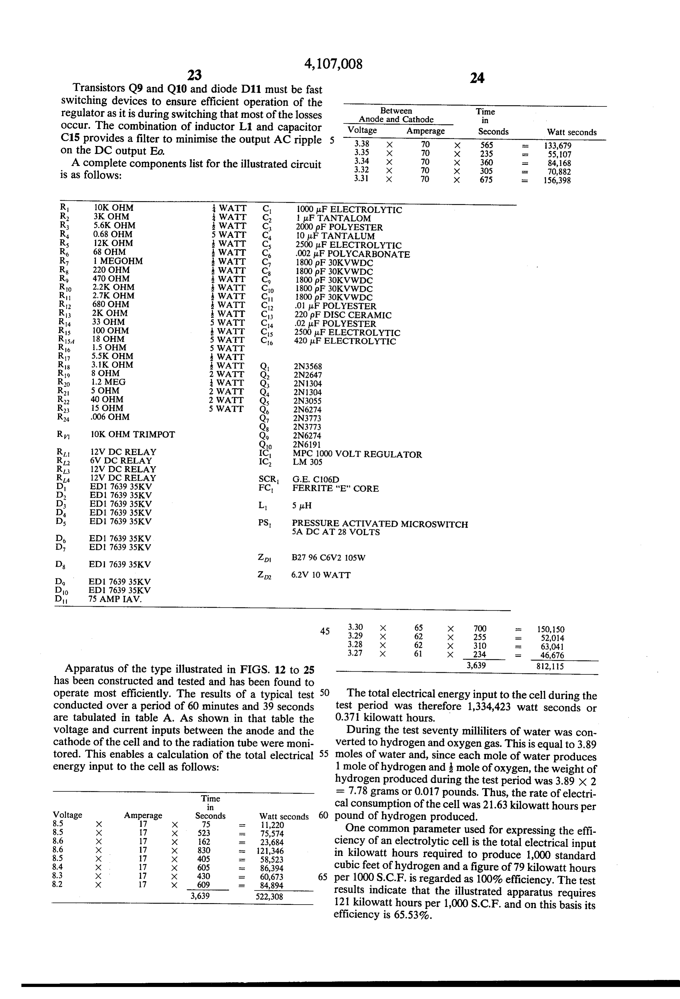
Page 27
Another basis for measuring the performance of elec TABLE A-continued trolytic cells is to calculate the thermal efficiency de Voltage to Voltage fined as
Inverter Circuit between Anode/Cathode
Time Volts Time Volts higher heating value of hydrogen produced X 100 5 1 min 15 8.5 3 min 25 3.38 electrical energy consumed 9 min 58 8.6 9 min 25 3.35 12 min 40 8.6 13 Inin 20 3.34 16 min 30 8.6 9 min 20 3.32
The higher heating value of hydrogen is defined as 286 20 min 20
kjoules per mole. Therefore, the thermal efficiency 33 min 15 8.4 35 min 50 3.30 demonstrated in the test was: 10 37 min 25 8.4 41 min 40 3.30 43 min 20 8.3 47 min 20 3.29 49 min 30 8.3 51 min 35 3.28 286 kix 70 moles 50 min 30
ki 58 min 25 8.2
The above results compare very favourably with the 15 Current to Inverter Circuit
Current between Anode/Cathode performance of the most efficient electrolysers which Time
Amps
Time
Amps
are at present commercially available. A comparison steady 9 min 06 70 with known electrolysers is set out in table B. It will be 60 min 32 7 12 min 40 70 seen that the only known electrolyser which operates at 20 18 min 05
the same efficiency levels is one produced by Life Sys High Voltage on Radiation Tube 29 min 55 70 tems Inc. However, this operates at very high pressure Time KV 36 min 30 68 and high temperature and is not available commercially. 11 min 25
Compared with the existing systems the present appara 20 min 15 40 53 min 30 62 tus operates at very low pressure and temperature and 28 min 10 40 56 min 20 62 has a high output for its size. It is also relatively cheap 25 3934 min 35 min 05
to produce. 42 min 50
TABLE A 53 min 05 37
RESULTS OF TEST ON APPARATUS OF FIGURES 12 - 26 Current between tube filament and anode varied 4.72 to Electrolyte . 25% of KOH 4.9 milliamps
Electrolyte volume at start of test period 600 ml Filament current varied 1.56 to 1.58 amps Electrolyte volume at end of test period 530 ml Filament voltage varied 2.68 to 2.65 volts Water converted during test period 70 m Maximum electrolyte temperature 54 C
Total duration of test period 60 mins 39
MAIN INFORMATION TAKEN FROMA PAPER TO OTHENTERSOCIETY ENERGY CONVERSON CONFERENCE
AUGUST 1975 BY KNOPIC & GREGORY OF INSTITUTE OF GAS TECHNOLOGY
Company and Commercially Weight Size Output Model Available bs. L' X W' X H' Rate Electrode
TELEDYNE ISOTOPES
Small Yes 80 O' x 14' x 26' .177c.ft. Porous per min.
Medium Yes 1000-2000 33' x 74' x 64' 177 to Porous lbs. per 7.06 c.ft.
Large (Multiple Yes 260s.ft. floor -4 tons Porous System Packages) space per basic per day
GENERAL ELECTRIC CO.
package
Solid Polymer Electrolyte Yes 30 <1 c.ft. Platinum
ELECTROLYSER CORP. - CANADA
Modular Stuart Cell 665 - 44' x 12-33' x 63.6 - Nickel Plated Steel
Stuart Package Hydrogen 25' x 48' x0 58' 20 c.ft. Nickel Plated Steel Generator per hour LITE SYSTEMS INC. No Noble Metal DE NORA Yes X96' x 63'
(Gold plated nickel)
Low Carbon Steel -rr- N.P. Anode COMINCO 41 tons Mild Steel (one of largest plants in world) per day N.P. Anode HORVATH SYSTEMS 1.45 liters per min.
Company and Operating Operating H. Thermal 1000 Model Pressure Temp. Produced Efficiency SCF
TELEDYNE ISOTOPES
Smal 130 F 55.4 31.8 310 Medium 70-100 30.4 58 170
Large (Multiple 100 p.s. i.g. 25.2 70 140 System Packages)
GENERAL ELECTRIC CO.
Solid Polymer Electrolyte 23.8 74 133.3
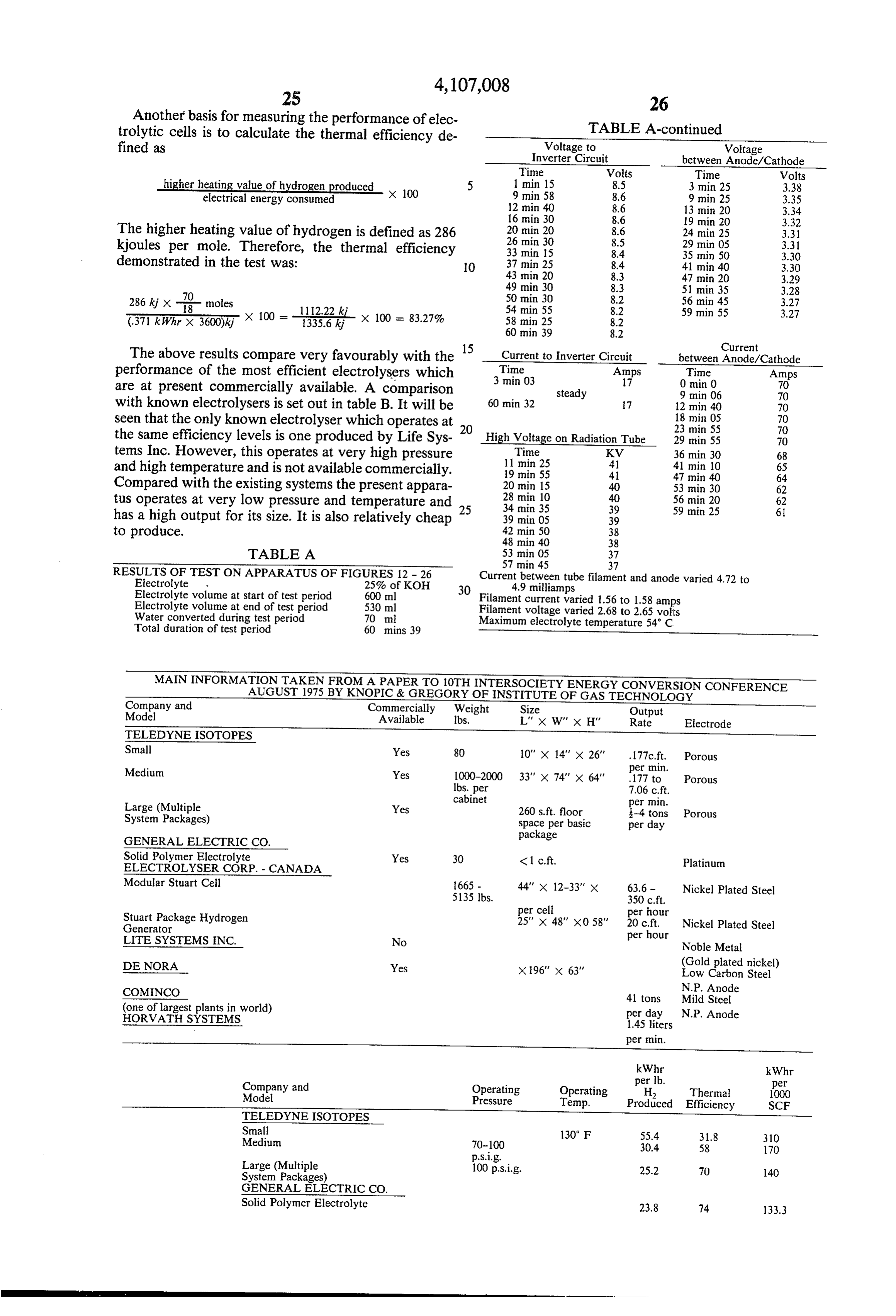
Page 28
MAIN INFORMATION TAKEN FROMA PAPER TO 10TH INTERSOCIETY ENERGY CONVERSION CONFERENCE
AUGUST 1975 BY KNOPIC & GREGORY OF INSTITUTE OF GASTECHNOLOGY
ELECTROLYSER CORP. - CANADA
Modular Stuart Cell 10' WG 70° C 24.5 72 28 Stuart Package Hydrogen
Generator 26.8 66 150 LIFE SYSTEMS INC. 600 p.s.i. 220 F 20.3 87 17 DE NORA 22.0 80 123.2 COMINCO 40 F 28.6 62 160 (one of the largest plants in world)
HORVATH SYSTEM Low 54 C 2.6 83.3 121
What I claim is: also produces a pulsed stream of neutrons associated 1. A method of decomposition of water to produce with said beam of electromagnetic radiation which hydrogen and oxygen comprising the steps of . " 15 stream of neutrons also enters the irradiated electrolyte placing an electrically conductive aqueous solution in and the hydrogen and the oxygen are collected as a vessel in contact with a pair of separated elec highly ionised gases in which the hydrogen comprises a trodes, higher proportion of deuterons than in naturally occur causing electric current to flow between said elec ring hydrogen.
trodes while simultaneously irradiating the aque 20 7. A method as claimed in claim 5 wherein said elec ous solution with electromagnetic radiation of tron bombardment is produced by applying between wave length less than 100 meters and a stream of the anode and a filament of said radiation tube a pulsat neutrons, and ing DC voltage of at least 17,000 volts and pulse fre collecting hydrogen and oxygen which accumulates quency of at least 3,000 pulses per second. at the electrodes as highly ionised gases in which 25 8. A method as claimed in claim 5 wherein there is the hydrogen contains a higher proportion of deu generated within the said vessel a magnetic field which trons than in naturally occurring hydrogen. in the vicinity of the irradiated electrolyte extends be 2. A method as claimed in claim 1 wherein said elec tween said electrodes and which in the vicinity of the trodes are cylindrically arranged about a common cen radiation tube is directed so as to accelerate the bom tre line and wherein the electromagnetic radiation and 30 bardment electrons.
said stream of neutrons are generated in a radiation 9. A method of decomposition of water to produce generator disposed within the inner electrode and radi hydrogen and oxygen comprising the steps of ate outwardly through the inner electrode into said placing an electrically conductive aqueous solution in aqueous solution. a vessel in contact with a pair of separated elec 3. A method as claimed in claim 2, wherein a mag 35 trodes netic field is applied to said aqueous solution in field irradiating the aqueous solution with electromagnetic directions extending between said electrodes which radiation of wavelength less than 100 meters magnetic field produces a "spin-flip' effect on protons while causing electric current to flow between said released from the aqueous solution. electrodes and collecting hydrogen and oxygen 4. A method as claimed in claim 1, wherein the stream 40 gases which accumulate therefrom. of neutrons is a pulsed stream of neutrons associated 10. A method as claimed in claim 9, wherein a pulsed with said electromagnetic radiation and wherein the stream of neutrons is associated with said electromag highly ionised hydrogen and oxygen gases are collected netic radiation and wherein the hydrogen and oxygen as a gaseous mixture. gases are collected as a highly ionized gaseous mixture 5. A method of decomposition of water to produce 45 in which the hydrogen contains a higher proportion of hydrogen and oxygen comprising the steps of deuterons than naturally occurring hydrogen. placing an electrically conductive aqueous solution in 11. A method as claimed in claim 10, wherein a mag a vessel in contact with a pair of separated elec netic field is applied to said aqueous solution in field trodes arranged cylindrically one within the other, directions extending between said electrodes. producing by electron bombardment of an anode in a 50 12. A method as claimed in claim 11, wherein the radiation tube disposed within the inner electrode a magnetic field produces a "spin flip' effect on portons beam of electromagnetic radiation of wave length released within the aqueous solution.
less than 100 meters which radiates outwardly 13. A method as claimed in claim 12, wherein said through the inner electrode to irradiate the aque magnetic field is generated by permanent magnets. ous electrolyte between the electrodes, 55 14. A method as claimed in claim 9, wherein said causing an electric current to flow between the elec electrodes are cylindrically arranged about a common trodes and through the irradiated electrolyte, and centre line and wherein the electromagnetic radiation is collecting hydrogen and oxygen gases which accu generated in a radiation generator disposed within the mulate at the electrodes. inner electrode and radiates outwardly through the 6. A method as claimed in claim 5, wherein the elec 60 inner electrode into said aqueous solution. tron bombardment of the anode in the radiation tube k k k sk. k.
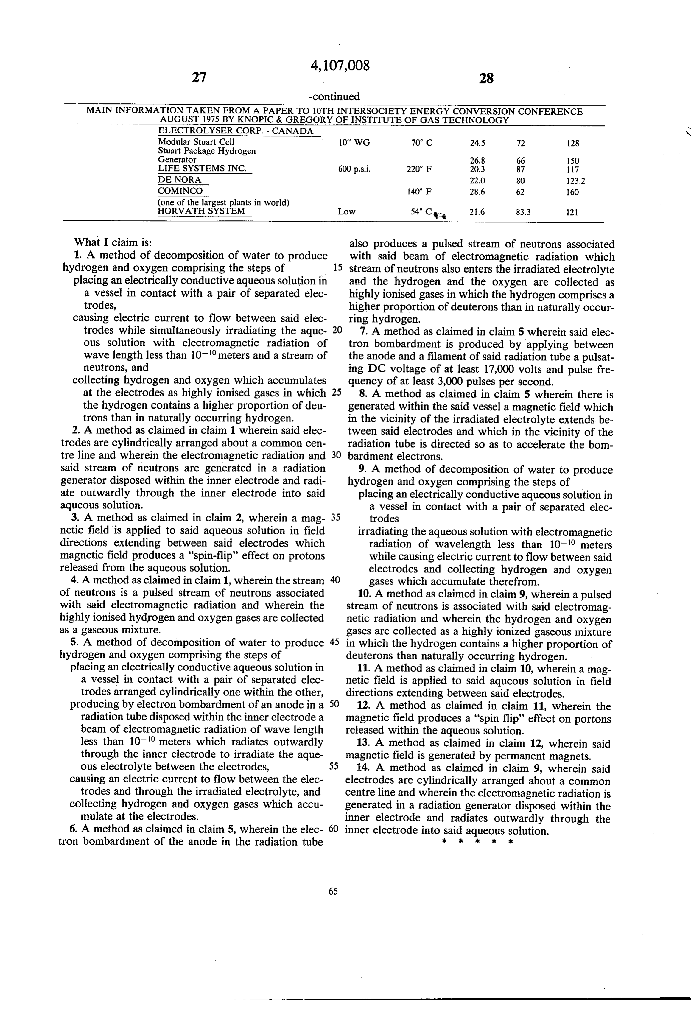
Page 29
UNITED STATES PATENT AND TRADEMARK OFFICE
CERTIFICATE OF CORRECTION
PATENT NO. : 4,107,008 Page l of 2
INVENTOR(S) : Stephen Horvath
It is Certified that error appears in the above-identified patent and that said Letters Patent are hereby COrrected as shown below:
Column l, line 44, "it" should be --It--.
Column 12, line 2l, "this" should be --This--.
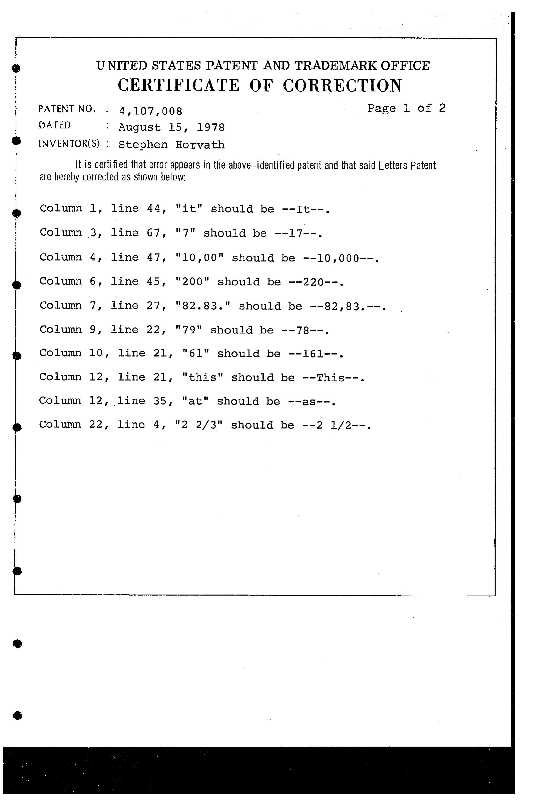
Page 30
UNITED STATES PATENT AND TRADEMARK OFFICE
CERTIFICATE OF CORRECTION
PATENT NO. : 4, 107,008 Page 2 of 2
INVENTOR(S) : Stephen Horvath
It is certified that error appears in the above-identified patent and that said Letters Patent are hereby corrected as shown below:
In the table spanning Columns 25 & 26, the height dimension for "Modular Stuart Cell" is missing. A height of -- 49"-- should be inserted.
Column 28, line 5l, "portons" should be --protons- . eigned and Sealed this
Tenth Day of April 1979
SEAL
Attest:
DONALD W. BANNER
RUTH C. MASON
Attesting Officer Commissioner of Patents and Trademarks
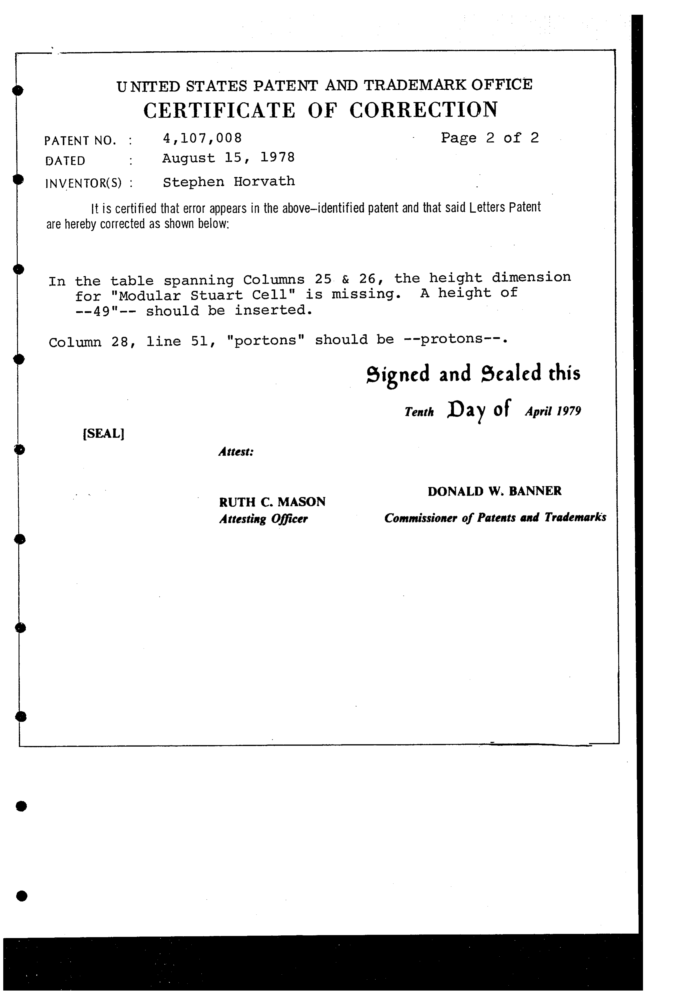
Provenance
- Collection
- Cited prior art
- Original PDF
- patentimages.storage.googleapis.com →
- Filed
- 1976-12-22
- Pages
- 30
- Method
- pdftotext (the PDF's own text layer) + pdftoppm 300dpi page scans
- Source
- Google Patents bibliographic record
- Granted
- 1978-08-15
- Inventors
- Stephen Horvath; Beeston Co Ltd
- Transcribed from
- patentimages.storage.googleapis.com →