patent · US6357223
Method and apparatus for enhancing the rate and efficiency of gas phase reactions
19 March 2002
Page 1 — bibliographic record
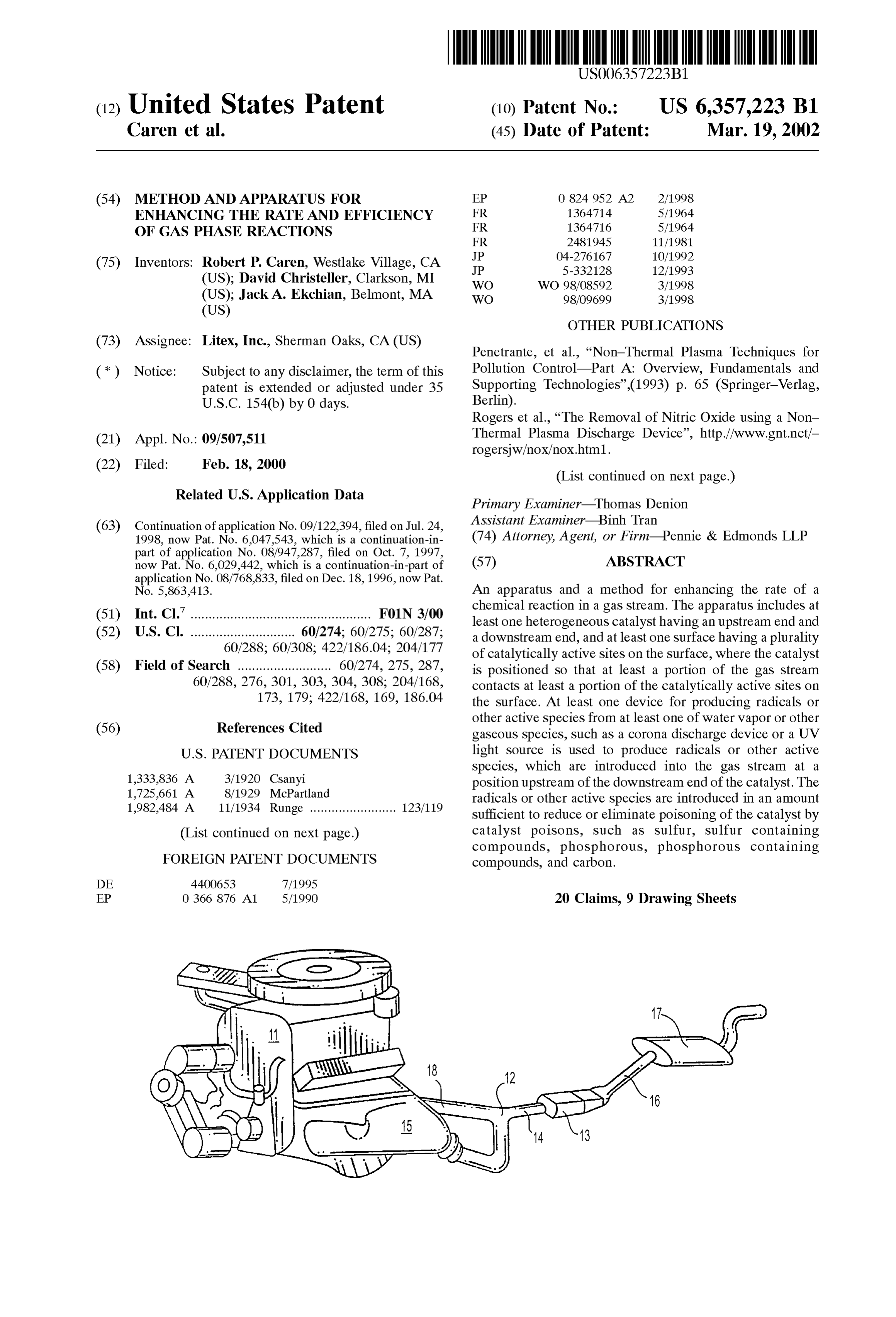
(12) United States Patent (10) Patent No.: US 6,357,223 B1 Caren et al. (45) Date of Patent: Mar. 19, 2002
(54) METHOD AND APPARATUS FOR EP
ENHANCING THE RATE AND EFFICIENCY
OF GAS PHASE REACTIONS FR 1364716 5/1964
(75) Inventors: Robert P. Caren, Westlake Village, CA JP 5-332128 12/1993 (US); David Christeller, Clarkson, MI WO WO 98/08592 3/1998
(US); Jack A. Ekchian, Belmont, MA WO 98/09699 3/1998
OTHER PUBLICATIONS
(73) Assignee: Litex, Inc., Sherman Oaks, CA (US)
Penetrante, et al., “Non-Thermal Plasma Techniques for (*) Notice: Subject to any disclaimer, the term of this Pollution Control-Part A. Overview, Fundamentals and patent is extended or adjusted under 35 Supporting Technologies”.(1993) p. 65 (Springer-Verlag, U.S.C. 154(b) by 0 days. Berlin).
Rogers et al., “The Removal of Nitric Oxide using a Non (21) Appl. No.: 09/507,511 Thermal Plasma Discharge Device', http://www.gnt.nct/-
(List continued on next page.)
Related U.S. Application Data Primary Examiner Thomas Denion
ASSistant Examiner Binh Tran (63) Continuation of application No. 09/122,394, filed on Jul. 24, (74) Attorney, Agent, or Firm-Pennie & Edmonds LLP 1998, now Pat. No. 6,047,543, which is a continuation-in part of application No. 08/947,287, filed on Oct. 7, 1997, (57) ABSTRACT now Pat. No. 6,029,442, which is a continuation-in-part of
No. 5,863,413. An apparatus and a method for enhancing the rate of a (51) Int. Cl." .................................................. F01N 3700 chemical reaction in a gas Stream. The apparatus includes at least one heterogeneous catalyst having an upstream end and (52) U.S. Cl. ............................. 60/274; 60/275; 60/287; a downstream end, and at least one Surface having a plurality 60/288; 60/308; 422/186.04; 204/177 of catalytically active sites on the Surface, where the catalyst (58) Field of Search .......................... 60/274, 275, 287, is positioned So that at least a portion of the gas Stream 60/288, 276,301, 303, 304, 308; 204/168, contacts at least a portion of the catalytically active sites on 173, 179; 422/168, 169, 186.04 the Surface. At least one device for producing radicals or
other active Species from at least one of water vapor or other gaseous Species, Such as a corona discharge device or a UV
Species, which are introduced into the gas Stream at a 1,333,836 A 3/1920 Csanyi position upstream of the downstream end of the catalyst. The 1,725,661 A 8/1929 McPartland radicals or other active Species are introduced in an amount 1982,484 A 11/1934 Runge ........................ 123/119 Sufficient to reduce or eliminate poisoning of the catalyst by (List continued on next page.) catalyst poisons, Such as Sulfur, Sulfur containing compounds, phosphorous, phosphorous containing
FOREIGN PATENT DOCUMENTS compounds, and carbon.
EP O 366 876 A1 5/1990 20 Claims, 9 Drawing Sheets
Page 2
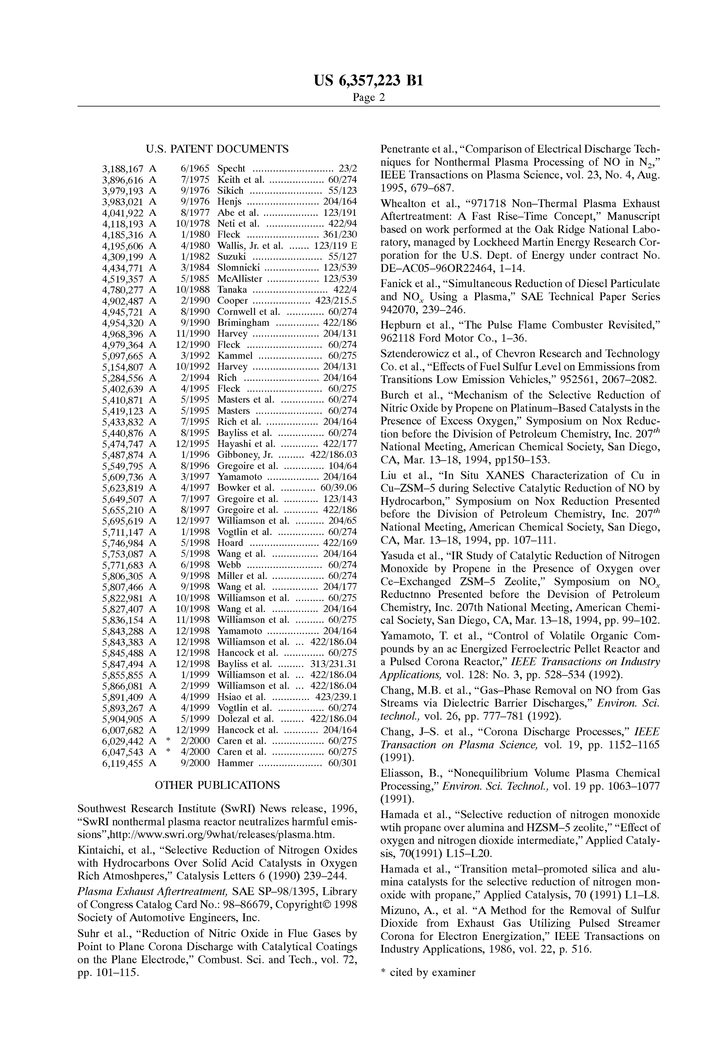
3,188,167 A 6/1965 Specht ............................ 23/2 niques for Nonthermal Plasma Processing of NO in N.” 3.896,616 A 7/1975 Keith et al. . ... 60/274 IEEE Transactions on Plasma Science, vol. 23, No. 4, Aug. 3,979,193 A 9/1976 Sikich ......................... 55/123 1995, 679-687.
3,983,021 A 9/1976 Henjs ..... ... 204/164 Whealton et al., “971718 Non-Thermal Plasma Exhaust 4,041.922 A 8/1977 Abe et al. ... ... 123/191 Aftertreatment: A Fast Rise-Time Concept,” Manuscript 4,118,193 A 10/1978 Neti et al. .................... 422/94 4,185.316 A 1/1980 Fleck ............... ... 361/230 based on work performed at the Oak Ridge National Labo 4,195,606 A 4/1980 Wallis, Jr. et al. 123/119 E ratory, managed by Lockheed Martin Energy Research Cor 4,309,199 A 1/1982 Suzuki ........................ 55/127 poration for the U.S. Dept. of Energy under contract No. 4,434,771 A 3/1984 Slomnicki. ... 123/539 DE-ACO5-96OR22464, 1-14.
4,519,357 A 5/1985 McAllister . ... 123/539 Fanicket al., “Simultaneous Reduction of Diesel Particulate 4,780.277 A 10/1988 Tanaka .......................... 422/4 4.902,487 A 2/1990 Cooper .......... 423/215.5 and NO. Using a Plasma,” SAE Technical Paper Series 4.945,721 A 8/1990 Cornwell et al. .... ... 60/274 942070, 239-246.
4.954,320 A 9/1990 Brimingham ..... ... 422/186 Hepburn et al., “The Pulse Flame Combuster Revisited.” 4968,396 A 11/1990 Harvey ...... ... 204/131 962 118 Ford Motor Co., 1-36.
4,979,364 A 12/1990 Fleck .......................... 60/274 5,097.665 A 3/1992 Kammel ...................... 60/275 Sztenderowicz et al., of Chevron Research and Technology 5,154,807 A 10/1992 Harvey ....................... 204/131 Co. et al., “Effects of Fuel Sulfur Level on Emmissions from 5,284,556 A 2/1994 Rich .......................... 204/164 Transitions Low Emission Vehicles,” 952561, 2067-2082. 5,402,639 A 4/1995 Fleck .......................... 60/275 5,410,871 A 5/1995 Masters et al. ... 60/274 Burch et al., “Mechanism of the Selective Reduction of 5,419,123 A 5/1995 Masters ......... ... 60/274 Nitric Oxide by Propene on Platinum-Based Catalysts in the 5,433,832 A 7/1995 Rich et al. ..... 204/164 Presence of Excess Oxygen,” Symposium on Nox Reduc
tion before the Division of Petroleum Chemistry, Inc. 207"
National Meeting, American Chemical Society, San Diego, 5,549.795 A 8/1996 Gregoire et al. .............. 104/64 CA, Mar. 13–18, 1994, pp 150–153. 5,609,736 A 3/1997 Yamamoto ........ ... 204/164 Liu et al., “In Situ XANES Characterization of Cu in 5,623,819 A 4/1997 Bowker et al. ... ... 60/39.06 Cu-ZSM-5 during Selective Catalytic Reduction of NO by 5,649,507 A 7/1997 Gregoire et al. ..... ... 123/143 Hydrocarbon,” Symposium on Nox Reduction Presented 5,655,210 A 8/1997 Gregoire et al. ..... 422/186 before the Division of Petroleum Chemistry, Inc. 207' 5,695,619 A 12/1997 Williamson et al. . ... 204/65 5,711,147 A 1/1998 Vogtlin et al. ....... ... 60/274 National Meeting, American Chemical Society, San Diego, 5,746,984 A 5/1998 Hoard ........... ... 422/169 CA, Mar. 13–18, 1994, pp. 107-111. 5,753,087 A 5/1998 Wang et al. ... ... 204/164 Yasuda et al., “IR Study of Catalytic Reduction of Nitrogen 5,771,683 A 6/1998 Webb ............ ... 60/274 Monoxide by Propene in the Presence of Oxygen over 5,806,305 A 9/1998 Miller et al. ... ... 60/274 Ce-Exchanged ZSM-5 Zeolite,” Symposium on NO 5,807466 A 9/1998 Wang et al. ......... 204/177 Reductinno Presented before the Devision of Petroleum 5,822,981 A 10/1998 Williamson et al. . ... 60/275 5,827.407 A 10/1998 Wang et al. ......... 204/164 Chemistry, Inc. 207th National Meeting, American Chemi 5,836,154 A 11/1998 Williamson et al. . ... 60/275 cal Society, San Diego, CA, Mar. 13-18, 1994, pp. 99-102. 5,843.288 A 12/1998 Yamamoto .................. 204/164 Yamamoto, T. et al., “Control of Volatile Organic Com
5,845.488 A 12/1998 Hancock et al. .............. 60/275 pounds by an ac Energized Ferroelectric Pellet Reactor and 5,847,494. A 12/1998 Bayliss et al. ......... 313/231.31 a Pulsed Corona Reactor," IEEE Transactions. On Industry 5,855,855 A 1/1999 Williamson et al. ... 422/186.04 Applications, vol. 128: No. 3, pp. 528–534 (1992). 5,866,081 A 2/1999 Williamson et al. ... 422/186.04 Chang, M.B. et al., “Gas-Phase Removal on NO from Gas
5,893,267 A 4/1999 Vogtlin et al. ................ 60/274 Streams via Dielectric Barrier Discharges,” Environ. Sci. 5,904.905 A 5/1999 Dolezal et al. ........ 422/186.04 technol, vol. 26, pp. 777–781 (1992). 6,007,682 A 12/1999 Hancock et al. ............ 204/164 Chang, J.-S. et al., “Corona Discharge Processes,” IEEE 6,029.442 A 2/2000 Caren et al. ...... ... 60/275 Transaction on Plasma Science, vol. 19, pp. 1152–1165 6,047,543 A * 4/2000 Caren et al. ... ... 60/275 (1991).
Eliasson, B., “Nonequilibrium Volume Plasma Chemical
OTHER PUBLICATIONS Processing," Environ. Sci. Technol, vol. 19 pp. 1063–1077
Southwest Research Institute (SwRI) News release, 1996, Hamada et al., “Selective reduction of nitrogen monoxide “SwRI nonthermal plasma reactor neutralizes harmful emis wtih propane over alumina and HZSM-5 zeolite,” “Effect of Sions'.http://www.SWri.org/9what/releases/plasma.htm. oxygen and nitrogen dioxide intermediate, Applied Cataly Kintaichi, et al., “Selective Reduction of Nitrogen Oxides sis, 70(1991) L15–L20.
with Hydrocarbons Over Solid Acid Catalysts in Oxygen Hamada et al., “Transition metal-promoted Silica and alu Rich Atmoshperes,” Catalysis Letters 6 (1990) 239-244. mina catalysts for the Selective reduction of nitrogen mon Plasma Exhaust After treatment, SAE SP-98/1395, Library oxide with propane," Applied Catalysis, 70 (1991) L1-L8. of Congress Catalog Card No. 98-86679, CopyrightC) 1998 Mizuno, A., et al. “A Method for the Removal of Sulfur Society of Automotive Engineers, Inc. Dioxide from Exhaust Gas Utilizing Pulsed Streamer Suhr et al., “Reduction of Nitric Oxide in Flue Gases by Corona for Electron Energization.” IEEE Transactions on Point to Plane Corona Discharge with Catalytical Coatings Industry Applications, 1986, vol. 22, p. 516. on the Plane Electrode,” Combust. Sci. and Tech., vol. 72, pp. 101-115. * cited by examiner
Page 3
Drawing sheet — no readable text.
Page 4
Drawing sheet — no readable text.
Page 5
Drawing sheet — no readable text.
Page 6
Drawing sheet — no readable text.
Page 7
Drawing sheet — no readable text.
Page 8
Drawing sheet — no readable text.
Page 9
Drawing sheet — no readable text.
Page 10
Drawing sheet — no readable text.
Page 11
Drawing sheet — no readable text.
Page 12
METHOD AND APPARATUS FOR and oxygen are combined at the electrodes, producing water ENHANCING THE RATE AND EFFICIENCY and an electric current. In addition to water, fuel cells that OF GAS PHASE REACTIONS utilize catalytic reactors to produce hydrogen gas from hydrocarbon fuels also release carbon dioxide, and may also
CROSS-REFERENCE TO RELATED release very Small amounts of carbon monoxide. APPLICATIONS Theoretically, a fuel cell is capable of producing electrical energy for as long as the fuel and oxidant are Supplied to the
This application is a continuation of Ser. No. 09/122,394 electrodes. However, pure hydrogen is difficult to Store, Jul. 24, 1998 U.S. Pat. No. 6,047,543. particularly in a vehicle, and its use may not be practical in The present application is a continuation-in-part of U.S. many applications. In those cases, a catalytic fuel reformer patent application Ser. No. 08/947,287, filed Oct. 7, 1997 may be used to produce hydrogen gas from a hydrocarbon now U.S. Pat. No. 6,029,442 which is a continuation-in-part fuel, and, thus, the life and performance of the fuel cell is of U.S. patent application Ser. No. 08/768,833, filed Dec. 18, limited by the performance and efficiency of the catalytic 1996 now U.S. Pat. No. 5,863,413, the teachings of which reactor. AS discussed above, if one or more catalyst poisons are incorporated herein in their entirety by reference. 15 are present in the fuel used to produce hydrogen in the catalytic fuel reformer, the performance of the reformer will
FIELD OF THE INVENTION be degraded, thereby reducing the performance of the fuel cell.
The present invention is directed to a method and appa In addition, fuel cells are Sensitive to carbon monoxide, ratus for improving and maintaining the performance of and, thus, the amount of carbon monoxide is typically catalytic reactors and catalytic convertors, particularly cata minimized lytic reactors used in fuel cells for producing electricity and to achieve inoptimum the fuel gas by removal by the catalytic reactor efficiency of the fuel cell. However, vehicle catalytic convertors used to reduce the emission of where the catalyst is contaminated or poisoned, carbon pollutants. More particularly, the invention is directed to a monoxide will remain in the fuel gas after passing through method and apparatus where the improved performance of 25 the catalytic reactor. Therefore, for the fuel cell to function the catalysts is achieved by producing highly oxidizing free efficiently, the catalyst should be substantially free of poi radicals, Such as hydroxyl radicals, OH, hydroperoxyl radicals, HO, atomic hydrogen, H, and atomic oxygen, O, sons fuel that prevent the removal of carbon monoxide from the gas.
and other active species, including related oxidizing gaseous Similarly, in Virtually all modern gasoline engines used in Species, Such as hydrogen peroxide, H2O, nitrogen dioxide, vehicles, Such as automobiles and light trucks, the exhaust NO, and OZone, O, by any means known in the art, but gases produced preferably with a corona discharge, and introducing these an exhaust pipeduring to a combustion of fuel are conveyed by catalytic converter where pollutants, active Species into the gas Stream flowing into and through such as carbon monoxide (CO), hydrocarbons (HC), and a catalyst, such as the catalytic reactor fuel reformer used to oxides of nitrogen (NO), are Substantially converted to produce hydrogen gas from a hydrocarbon fuel for use in a non-polluting Species, and, thus, are removed from the
fuel cell, a catalytic combuster, or a catalytic convertor exhaust gas. In addition, it is expected that catalytic con asSociated with an internal combustion engine. Vertors will Soon be developed for use with diesel engines. BACKGROUND OF THE INVENTION Most modern engines employ three way catalytic converters (“TWC), which simultaneously oxidize CO and HC to CO.
Heterogeneous catalysts have been shown to be useful in 40 and H2O, and reduce NO and NO to N. The amount of CO, enhancing the rate and/or efficiency of gas phase reactions in HC, NO, and other pollutants produced will vary with the a number of applications. These applications include emerg design and operating conditions of the engine and the fuel ing technologies, Such as catalytic reactors or fuel reformers and air used. In particular, as with fuel cell catalytic reactors, that are used to produce hydrogen gas, H, from hydrocar the presence of catalyst poisons in the fuel will result in a bon fuels, Such as gasoline, natural gas, and alcohols, as well 45 degradation of the performance of the catalytic convertor, as relatively mature technologies, Such as the catalytic and, thus, an increase in the amount of pollutant released convertors used to reduce the emission of pollutants from into the air.
automobile and truck engines. The performance of hetero In general terms, a catalytic convertor used with an geneous catalysts may be Severely degraded by exposure to internal or external combustion engine may be considered to catalyst poisons, Such as the Sulfur and phosphorous com 50 be a Sophisticated catalytic combuster, which is typically pounds that are found in varying amounts in automotive used to enhance the oxidation of a fuel to produce heat. The fuels, Such as gasoline. AS gasoline is expected to be used, heterogeneous catalyst in a catalytic combuster provides a at least initially, in automotive applications of fuel cells, the Surface on which a fuel and an oxidizer react. In a typical possible poisoning of both fuel cell catalytic reactors, auto catalytic combuster, a vaporized fuel and air are passed over motive catalytic convertors, and other catalytic combusters 55 the Surface of the catalyst. By providing a catalytic Site for by fuel contaminants is a major concern regarding the the reaction of the fuel and oxidizer, the catalyst lowers the effectiveness of these devices. activation energy of the reaction, allowing the reaction to Fuel cells are electrochemical devices that convert the occur at a lower temperature with greater efficiency. chemical energy of a fuel directly into electrical and thermal However, the presence of catalyst poisons that may be energy, and have been used for a number of years in 60 adsorbed onto the catalyst Surface in any of the fuel, aerospace applications, Such as the Space Shuttle, where oxidizer, or reaction products will degrade the performance hydrogen and oxygen gas are combined to produce electric and the efficiency of the catalytic combuster by occupying power. In a typical fuel cell, a gaseous fuel, e.g., hydrogen, active sites on the catalyst Surface. This reduces the number H, is fed continuously to an anode or negative electrode of Sites available to the fuel and oxidizer, decreasing the compartment, and an oxidant, e.g., OXygen or an oxygen 65 reaction rate.
containing gas, which is typically air, is fed continuously to In general terms, the heterogeneous catalysts, used in fuel a cathode or positive electrode compartment. The hydrogen cell catalytic fuel reformers or reactors, vehicle catalytic
Page 13
convertors, and catalytic combusters, provide a catalytic performance of catalytic convertors, catalytic fuel reformers Surface that enhances the reaction rate and efficiency of or reactors, catalytic combustors of various types, and various gas phase reactions. Although a number of different heterogeneous catalysts in general are affected by Such heterogeneous catalysts are known, the heterogeneous cata poisons. Poisons, even in Small concentrations, Strongly lysts used in catalytic reactors and catalytic convertors bond to catalytic Sites on the Surface of the catalyst, and usually utilize a noble metal catalyst. The structure of the block the completion of the chemical processes that the catalyst Support may vary, depending on the application, catalyst is intended to promote. The poisoning of vehicular e.g., ceramic beads that are coated with the catalytic material catalytic convertors by Sulfur in gasoline has been a may be used. However, where a large throughput of gas is problem, and is expected to also be a Severe problem in fuel required, the noble metal catalyst is preferably held in a cell catalytic reactors that are proposed for automotive honeycomb monolithic Structure, which has excellent applications, where the required hydrogen gas will, in all Strength and crack-resistance under physical and thermal likelihood, initially be produce from gasoline. Shock. The issue of catalyst poisoning is not new. For example, The honeycomb construction and the geometries chosen the effectiveness of automotive catalytic convertors is provide a relatively low pressure drop and a large total 15 Severely degraded by the presence of lead in gasoline. Surface area that enhances the mass transfer controlled Therefore, the introduction of catalytic convertors on pro reactions that produce fuel for the fuel cell or remove duction automobiles in the mid-1970's required the elimi pollutants from the exhaust of an engine. The honeycomb is nation of tetra-ethyl lead as an octane enhancer in fuels. often Set in a Steel container, and protected from Vibration by Although the elimination of the lead based octane enhancer a resilient matting where needed. Although a Single catalyst required research into alternative octane enhancers, it did not may be use, a typical modern three way catalytic convertor require any major changes in the manner in which the fuel comprises an outer Steel shell that contains at least two itself is refined, and, thus, the cost of eliminating tetra-ethyl honeycomb catalyst “bricks', i.e., honeycomb monolithic lead from gasoline was not prohibitive. However, the elimi Structures holding the noble metal catalyst, as described nation of Sulfur, a naturally occurring element in crude oil, above, where one of the brickS is mounted at the upstream, 25 from fuel may be far more expensive. inlet end of the catalytic convertor, and the Second is Now that lead has been essentially eliminated from motor mounted at the downstream, outlet end of the catalytic vehicle fuel in the United States, sulfur is the key component COnVertOr. in gasoline responsible for the poisoning of catalysts. Sulfur, An adherent washcoat, frequently made of Stabilized typically adsorbed in the form of oxides of sulfur, attaches gamma alumina or corderite into which the catalytic com or binds to catalytically active areas on the Surface of the ponents are incorporated, is deposited on the walls of the catalyst, Such as those used in catalytic combusters, catalytic honeycomb. Modern three way catalytic converters for convertors, and catalytic fuel reformerS or reactors. The Simultaneously converting all three pollutants typically uti adsorption of at least one of Sulfur and Sulfur compounds lize the precious or noble metals platinum (Pt) and rhodium 35 prevents the resulting poisoned areas from participating in (Rh), where the Rh is most responsible for the reduction of the gas phase reaction, Such as the oxidation of HC and CO, NO, while also contributing to CO oxidation, which is and the reduction of NO in an automotive catalytic primarily performed by Pt. Recently palladium, Pd, which is convertor, and thereby reduces the efficiency of the catalyst. leSS expensive, has been Substituted for or used in combi AS a result, the emission of pollutants is increased where the nation with Pt and Rh. The active catalyst generally com catalyst is used in an internal combustion engine catalytic prises about 0.1 to 0.15% of these metals. For other 40 convertor. Similarly, it is expected that the presence of Sulfur applications, where reduction of NO is not required, so that in gasoline will degrade the performance of catalytic reac only the oxidation of CO or HC are required, rhodium is tors used to produce hydrogen from gasoline to be used as typically not present in the catalyst. Instead the catalyst is fuel in a fuel cell.
platinum, palladium, or a combination of platinum and 45 The Sulfur content of gasoline presently varies from State palladium. to state and from refinery to refinery. Where California has Because the exhaust gases of the combustion proceSS in a limit on gasoline Sulfur content of approximately 30 parts most modern automotive gasoline engines tend to oscillate per million by weight (ppm), other States have much from Slightly rich to slightly lean, an oxygen Storage higher limits on Sulfur, and, as a result, Sulfur levels in fuel medium is added to the Washcoat of vehicular catalytic 50 can exceed 900 ppm. Therefore, there has been a push within convertors to adsorb oxygen onto the Surface of the wash the Environmental Protection Agency ("EPA") to set a coat during any lean portion of the cycle, and release the national Standard for gasoline Sulfur content. However, even oxygen for reaction with exceSS CO and HC during any rich at the proposed level of 80 ppm, a degradation of the portion of the cycle. Cerium Oxide (CeO) is frequently performance and efficiency of catalytic convertors and cata used for this purpose due to its desirable reduction-oxidation 55 lytic reactors using a fuel containing that level of Sulfur is response. expected.
The conversion efficiency of a gas phase reaction hetero Alternative methods for reducing Sulfur poisoning of geneous catalyst is measured by the ratio of the rate of mass heterogeneous catalysts are available. For example, the conversion or removal of a particular constituent of interest catalyst may be heated to a temperature significantly higher to the mass flow rate of that constituent into the catalytic. 60 than the normal operating temperature to decompose and/or The conversion efficiency of a catalyst is a function of many drive off certain poisons, and thereby recover the poisoned parameters including aging, temperature, Stoichiometry, the catalyst. However, the high temperature required can Sig presence of any catalyst poisons, Such as lead, Sulfur, carbon nificantly reduce the life expectancy of a catalytic device, and phosphorous, the type of catalyst, and the amount of and is frequently not possible during normal operation. time the gases reside in or on the catalyst. 65 Attempts to remove the Sulfur compounds that poison AS discussed above, catalyst poisons, Such as Sulfur and catalysts from the gas or exhaust Stream before poisoning of phosphorous, degrade the performance of catalysts. The the catalyst occurs by direct filtering or by oxidation of SO
Page 14
S 6 to SOs, either catalytically in the presence of oxygen, i.e., The at least one device for producing radicals or other lean conditions, or in a plasma discharge, have been largely active Species is preferably a corona discharge device, unsuccessful. While each of these methods has been having a power Supply. Preferably, the corona discharge explored for automotive applications, they often fail to device and the power Supply are each designed to have a remove any significant amount of Sulfur or oxides of Sulfur, mechanical natural resonant frequency significantly higher and require significant amount of power. Moreover, these than that produced by the internal combustion engine. methods may not be feasible with fuel cell catalytic fuel Preferably, the power Supply is a low power power Supply, reformers at all. typically producing no more than about 200 watts of power, Therefore, a need exists for a simple, inexpensive means preferably no more than about 100 watts of power, most of maintaining the efficiency of gas phase heterogeneous preferably no more than about 30 watts of power. catalysts, Such as those used in automotive catalytic The corona discharge device may be positioned Such that convertors, fuel cell catalytic reactors, and catalytic com naturally occurring pressure fluctuations in the exhaust busters. The present invention provides Such a means. Stream provide a pumping action that forces exhaust gas into SUMMARY OF THE INVENTION the corona discharge device, and Scavenges gases containing 15 radicals produced in the corona discharge from the corona
The present invention is directed to an apparatus for enhancing the rate of a chemical reaction in a gas Stream. discharge device. To increase the benefit obtained from these The apparatus comprises at least one heterogeneous catalyst preSSure fluctuations, a plenum may be positioned adjacent having an upstream end, a downstream end, and at least one to the corona discharge device, Such that exhaust gas pass from the exhaust pipe, through the corona discharge, into the
Surface having a plurality of catalytically active sites on the plenum, and back into the exhaust pipe. Surface, and at least one device for producing radicals or other active species from water vapor and/or other gaseous The apparatus of the invention may also comprise a Species, Such as an ultra Violet light Source, a corona device for injecting air into the exhaust Stream during fuel discharge device, or any other means known in the art for rich cold Start operating conditions, Such that the corona discharge causes the combustion of residual fuel in the forming radicals or other active Species in a gas Stream. The 25 exhaust catalyst is positioned So that at least a portion of the gas Stream.
Stream contacts at least a portion of the catalytically active The apparatus of the invention may also utilize a remote Sites on the Surface, and the radicals or other active Species device for generating the radicals and other active species. are introduced into the gas Stream at a position upstream of With an internal combustion engine, this embodiment fur the downstream end of the catalyst. The at least one device ther comprises an exhaust pipe attached to the inlet of the for producing radicals or other active Species from water catalytic convertor, a tailpipe attached to the outlet of the Vapor and/or other gaseous species may be positioned within catalytic convertor, Such that at least a portion of the exhaust the gas Stream, Such that radicals are produced directly in the Stream passes from the exhaust pipe to and through the gas Stream, or it may be positioned remotely, producing the catalytic convertor and through the tailpipe. The tailpipe has radicals or other active Species either from a portion of the 35 an exhaust gas takeoff for conveying a portion of the exhaust gas Stream that has been diverted to the remote device or Stream to a remote radical generator, which comprises the at from Some other Source of gas. least one device for producing radicals or other active Preferably, the radicals or other active Species are intro Species in the exhaust gas in the portion of the exhaust duced in an amount Sufficient to reduce or eliminate poi Stream conveyed to the remote radical generator. An output Soning of the catalyst by catalyst poisons, Such as Sulfur, 40 from the remote radical generator returns the exhaust gas Sulfur containing compounds, phosphorous, phosphorous containing radicals or other active Species from the remote containing compounds, or carbon. radical generator to the exhaust Stream at a point upstream Typically, the catalyst is a part of a fuel cell catalytic of the downstream end of at least one catalyst in the catalytic reactor, an automotive catalytic convertor, or a catalytic convertor, where the exhaust gas containing radicals is combuster. Where, the gas Stream is an exhaust Stream from 45 injected into the exhaust Stream.
an internal combustion engine. The internal combustion In a further embodiment, the invention is directed to an engine may be a Stoichiometric engine, a lean burn engine, apparatus for reducing at least one pollutant in an exhaust a diesel engine, or any other known type of engine. gas Stream containing an exhaust gas formed from the For use with an internal combustion engine, the apparatus combustion of fuel in a combustion gas Stream, which of the invention may further comprise a catalytic convertor, 50 comprises a precombustion gas Stream and the exhaust gas having an inlet and an outlet, and comprising the at least one Stream. The combustion gas Stream may be that of a catalytic catalyst, where the catalytic convertor is positioned Such that combuster, internal or external combustion engine, furnace, at least a portion of the exhaust Stream from the engine boiler, fuel cell catalytic fuel reformer, electrical power passes through the catalytic convertor. Typically, an exhaust generator, or any other device that obtains energy from the pipe is attached to the inlet of the catalytic convertor, Such 55 combustion of fuel to which a catalyst can be adapted to that at least a portion of the exhaust gas Stream passes reduce the emission of pollution.
through the exhaust pipe to and through the catalytic con The apparatus comprises at least one catalyst, having an Vertor and the at least one catalyst, and at least one of the upstream end and a downstream end, where the at least one catalytic convertor or the exhaust pipe comprises a fitting for catalyst is positioned Such that at least a portion of the positioning a device for producing radicals or other active 60 exhaust gas Stream passes through the at least one catalyst, Species in the exhaust Stream or a portion thereof, So that a and at least one device for producing radicals or other active radicals or other active Species are produced in the exhaust Species from water vapor or other gaseous Species posi Stream upstream of the downstream end of at least one tioned in the combustion gas Stream, wherein the radicals are catalyst in the catalytic convertor. To prevent water that may introduced into the combustion gas Stream upstream of the condense during cool down, the at least one device for 65 downstream end of the at least one catalyst. Preferably, the producing radicals or other active Species may be positioned device for producing radicals or other active Species is a on top of the exhaust pipe or catalytic convertor. corona discharge device.
Page 15
In a further embodiment, the apparatus is directed to a fuel "upstream” refers to a position in the gas Stream located cell catalytic reformer comprising a partial oxidation Stage, relative to a Second position in the gas Stream in the direction a catalytic reactor Stage, and a preferential oxidation Stage, opposite to the flow of the gas Stream, i.e., in the direction wherein the radicals or other active Species are introduced of the Source of the gas Stream, and the term "downstream” into at least one of the partial oxidation Stage, catalytic refers to a position in the gas Stream located relative to a reactor Stage, or preferential oxidation Stage comprises a Second position in the gas Stream in the direction of the flow catalyst. As with the embodiments described above, the at of the gas Stream. Therefore, where a point is located least one device for producing radicals or other active upstream of, e.g., a catalyst or a part of a catalyst, the point Species is preferably a corona discharge device. The device is positioned in the gas Stream between the catalyst or part for producing radicals or other active Species is positioned of the catalyst and the Source of the gas, and, where a point within the gas Stream, or may be positioned remotely.
The present invention is also directed to a method of is locatedthedownstream of, e.g., a catalyst or a part of a enhancing a gas phase chemical reaction in a gas Stream. The catalyst, catalyst or part of the catalyst it is positioned in method comprises contacting the gas Stream with at least the gas Stream between the Source of the gas and the point. one heterogeneous catalyst having an upstream end, a down 15 AS used herein, the term “pre-combustion gas Stream” Stream end, and at least one Surface having a plurality of refers to the flow of air or of the air/fuel mixture to the catalytically active sites, Such that at least a portion of the combustion chamber. The terms “postcombustion gas gas Stream contacts at least a portion of the catalytically Stream” and “exhaust gas Stream”, as used herein, refer to active sites, forming radicals or other active gaseous Species the resulting flow of exhaust gases from the combustion either directly in the gas Stream or in a remote generator, and chamber following combustion or oxidation of the air/fuel or introducing the radicals or other active gaseous Species into oxidant/fuel mixture. The pre-combustion and postcombus the gas Stream at a point upstream of the downstream end of tion gas Streams are collectively referred to as the “com the catalyst. Preferably, the radicals or other active Species bustion gas Stream'.
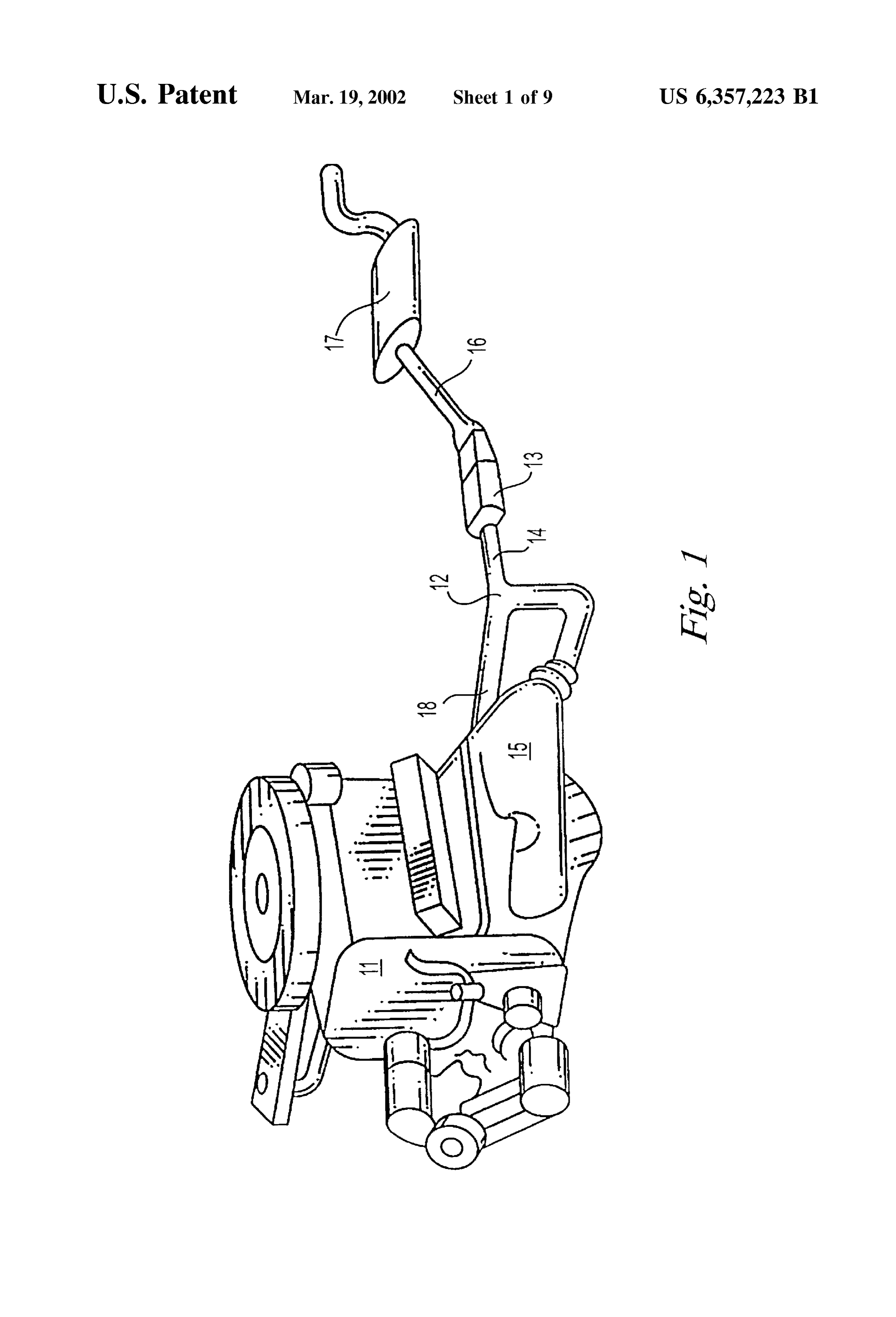
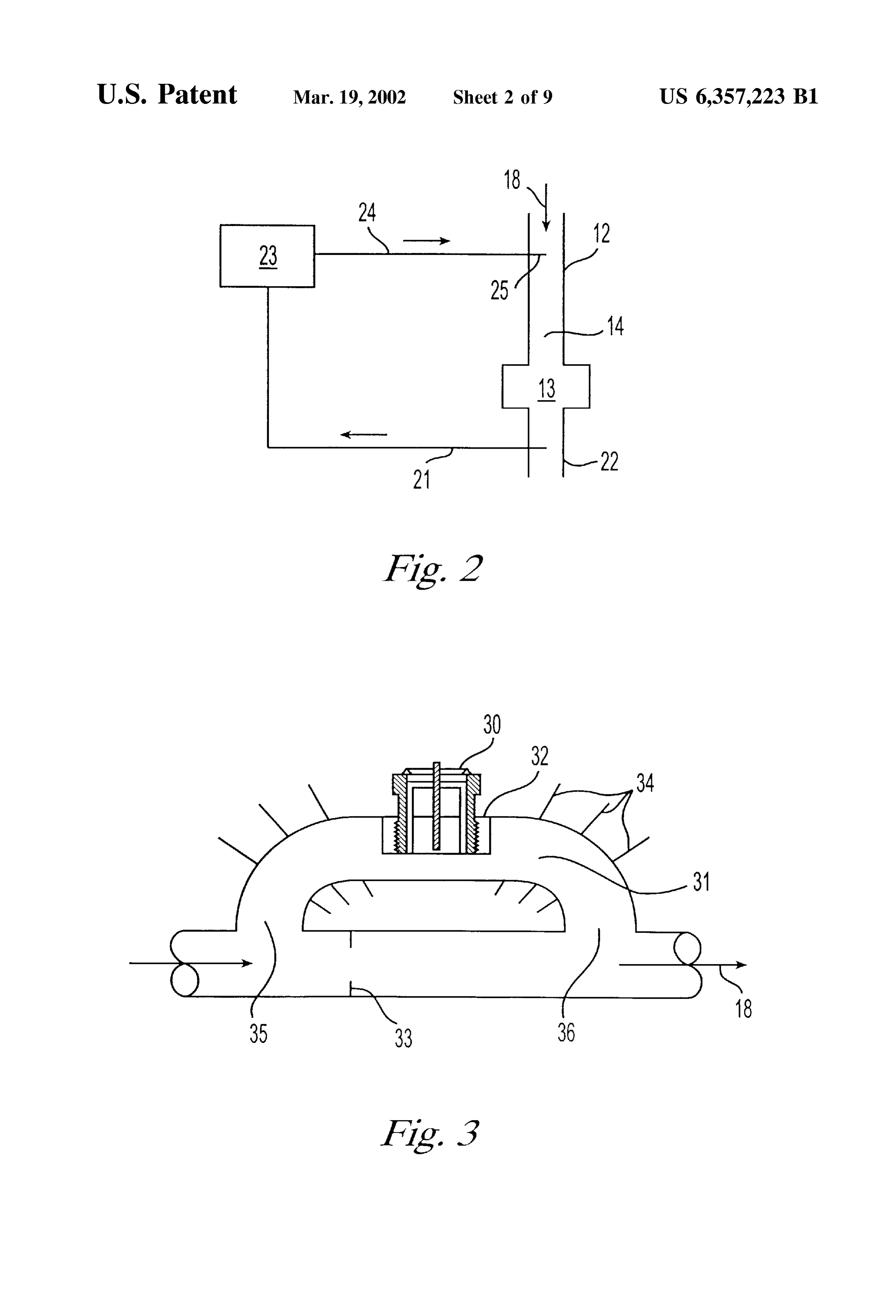
are introduced into the gas Stream whenever the gas Stream As used herein, the term “catalytic combuster” refers to is in contact with the catalyst, i.e., the radicals or other active any device in which a fuel is combusted or oxidized on the Species are introduced Starting with the initial use of the 25 Surface of a heterogeneous catalyst. That is, any device in catalyst. This is known as time Zero injection. which the reaction of a fuel and oxidizer is enhanced by BRIEF DESCRIPTION OF THE DRAWINGS contact with a heterogeneous catalyst. FIG. 1 is a side perspective view of an internal combus radical” In addition, the terms “radical' or “radicals” and “free tion engine having a catalytic converter: or “free radicals' refer to any atom or group of FIG. 2 is a Schematic of an exhaust System incorporating electricalatoms having at least one unpaired electron and no net a remote corona discharge generator of chemically active electricallycharge; i.e., as used herein, these terms refer to neutral Species having equal numbers of elec
Species. trons and protons, Such as hydroxyl radical, OH, and hydro FIG.3 illustrates a corona discharge device mounted in an gen and oxygen atoms, H and O respectively, which may exhaust shunt. 35 also be represented by OH*, H*, and O*, where “*” repre
FIG. 4 illustrates a corona discharge device having con Sents the unpaired electron.
centric electrodes and a dielectric coated inner electrode.
AS used herein, the terms “gas phase heterogeneous
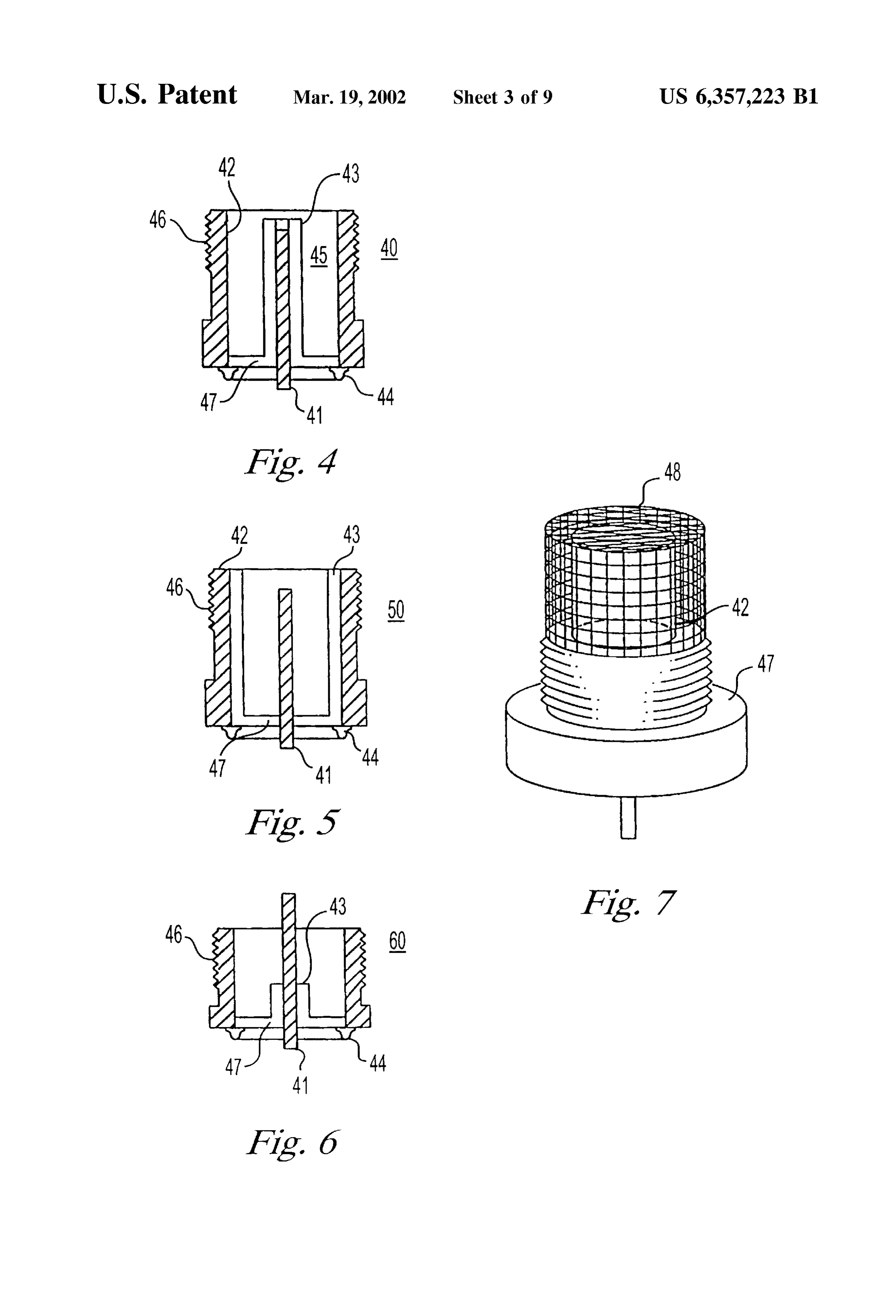
FIG. 5 illustrates a corona discharge device having con catalyst” and "heterogeneous catalyst” refer to any non centric electrodes and a dielectric coated outer electrode. gaseous catalytic material having a Surface that enhances the FIG. 6 illustrates a distant ground corona discharge 40 rate or efficiency of a gas phase reaction. i.e., a chemical device. reaction that alters the chemical Structure of at least one FIG. 7 illustrates a corona discharge device of the type gaseous chemical Species.
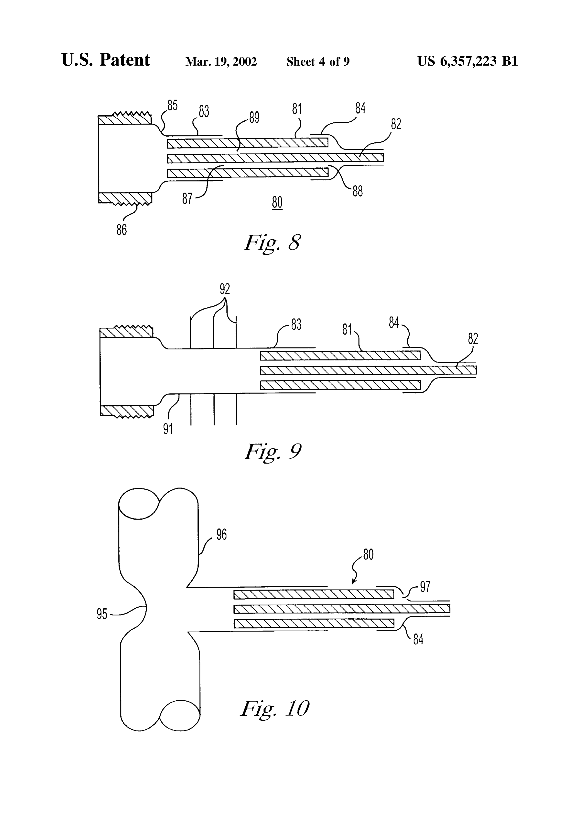
depicted in FIG. 5 equipped with a flame arrester. AS used herein the terms “automotive catalytic convertor” FIG. 8 illustrates a compact corona discharge device. 45 and "vehicular catalytic convertor” refer to any catalytic FIG. 9 illustrates a compact corona discharge device device that may be used to reduce the emission of pollutants having an extended skirt. produced by the combustion of fuel in the engine of an FIG. 10 illustrates a compact corona discharge device automobile, truck, or motorcycle, or any other type of equipped with an orifice for injecting air. vehicle or device that uses an internal or external combus FIG. 11 illustrates a corona discharge device mounted in 50 tion engine as a Source of power.
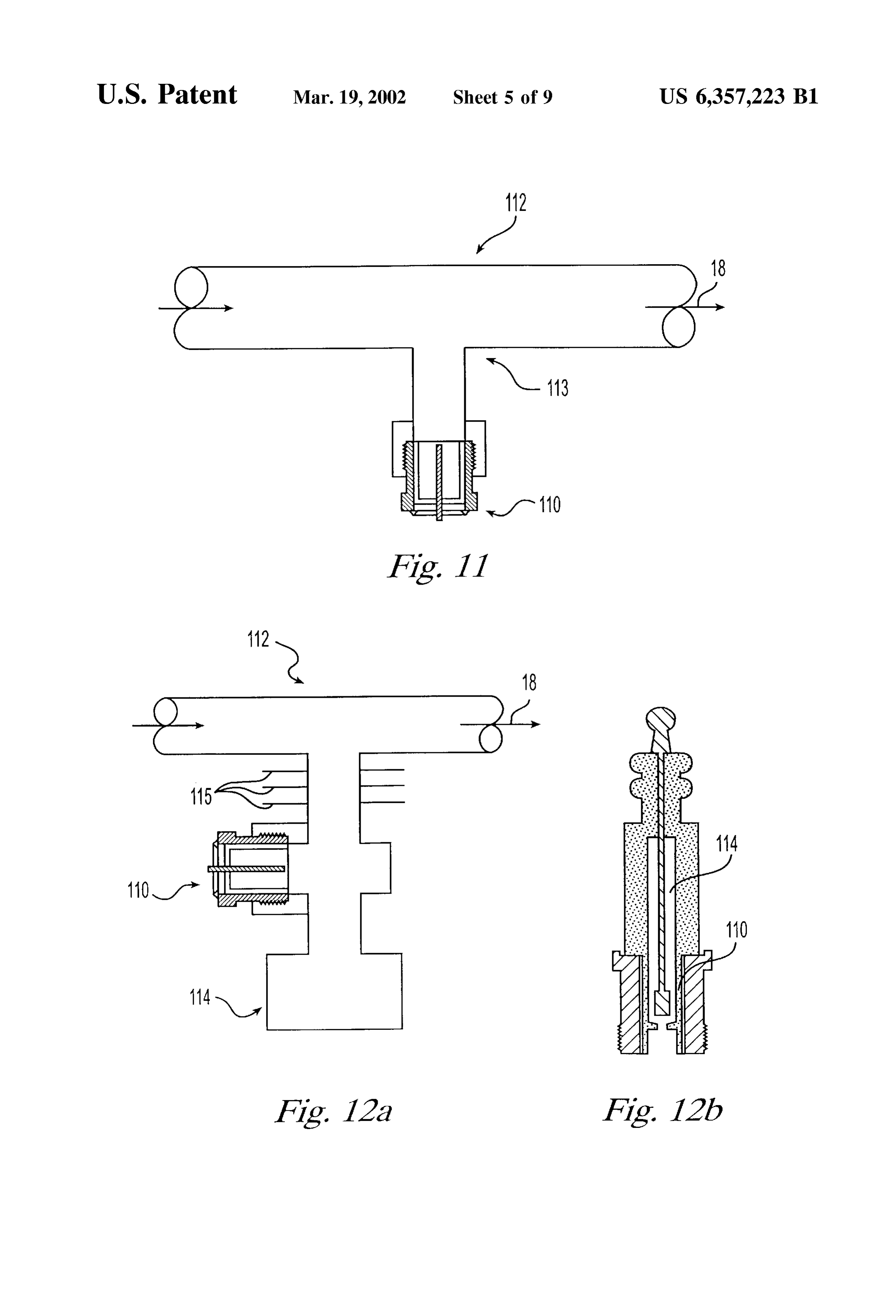
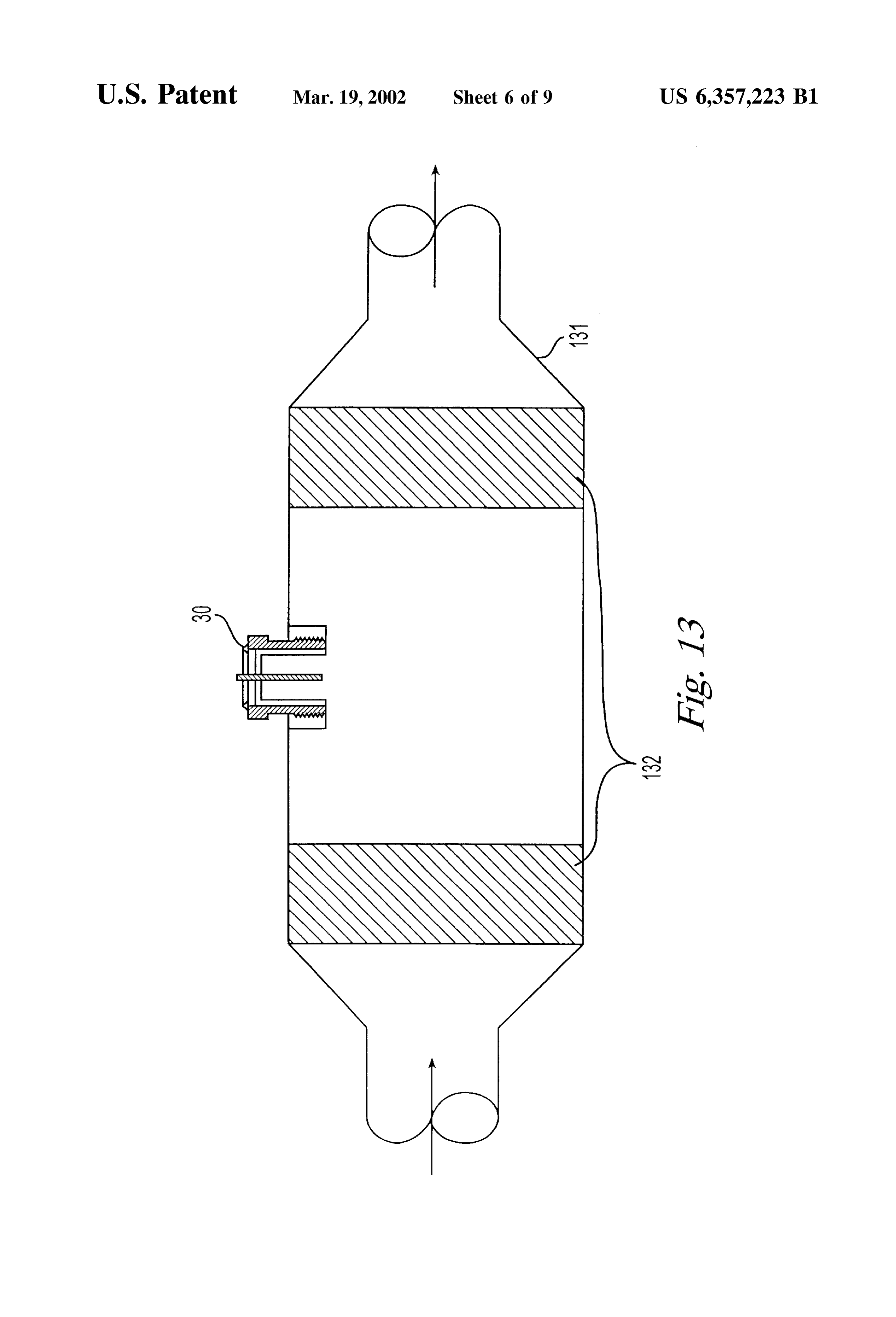
a manner that takes advantage of the pumping action of AS used herein, the term “introduction of radicals into the preSSure variations in the exhaust gas Stream. gas Stream” includes the introduction of radical and/or FIGS. 12a and 12b illustrate corona discharge devices related oxidizing Species that were produced in a remote mounted in conjunction with or incorporating a plenum that radical generator and the direct in Situ production of radicals augments the pumping action of preSSure variations in the 55 and/or oxidizing species directly in the gas Stream. exhaust gas Stream. The present invention is directed to an apparatus and FIG. 13 illustrates the use of a corona discharge device method for enhancing the rate and efficiency of gas phase with a catalytic convertor. reactions within a gas Stream and for maintaining and FIG. 14 is a schematic of a fuel cell catalytic fuel improving the efficiency and performance of the heteroge reformer. 60 neous catalysts used to enhance the rate of Such gas phase FIG. 15 is a Schematic of an example of a power Supply reactions. Typically, the heterogenous catalysts are of the circuit for use with a corona discharge device. type found in catalytic combusters, fuel cell catalytic reformers, and automotive catalytic convertors.
DETAILED DESCRIPTION OF THE In the present invention, highly oxidizing free radicals, PREFERRED EMBODIMENTS 65 Such as hydroxyl radicals, OH, hydroperoxyl radical, HO, As used herein the term “gas stream” refers to any flow of atomic hydrogen, H, and atomic oxygen, O, and other active gas to, from, through, or over an article or device. The term Species, including related oxidizing gaseous Species, Such as
Page 16
hydrogen peroxide, H2O, nitrogen dioxide, NO, and method and apparatus of the invention are used with an oZone, O, are produced in or added to a gas stream, Such as, internal combustion engine further comprising at least one e.g., the combustion gas Stream of a catalytic combuster or oxygen Sensor upstream of the catalytic convertor. The of an internal combustion engine equipped with a catalytic oxygen Sensor provides data to the fuel injection System of convertor, or the gas Stream of a fuel cell catalytic reformer, the engine that allows the fuel injection System to maintain where the gas Stream passes over or through a heterogeneous a Stoichiometric air/fuel ratio.
catalyst in a manner that allows at least a portion of the gas It has been discovered that the presence of OH, as well as Stream to contact at least a portion of the catalyst. The that of other active or reactive species, Such as other free radicals and oxidizing Species are produced in either a radicals and gaseous molecular intermediates and oxidizers, remote generator, and then introduced into the gas Stream, including O, H, NO2, H2O, HO, and O, in the exhaust or, where the gas Stream contains chemical Species that can gases of a combustion engine in the presence of the requisite be converted into the desired radicals or oxidizing Species oxygen, provides a highly effective catalytic conversion of under the proper conditions, the radicals and oxidizing CO and hydrocarbons to non-polluting gas Species, i.e., CO Species may be formed directly within the gas Stream. The and water vapor. The OH and other related free radical and radicals may be introduced or produced at any point within 15 gaseous molecular oxidizers created by reaction of OH with the gas Stream upstream of the downstream end of the gaseous species in the exhaust Stream act as catalysts catalyst, i.e., the portion of the catalyst farthest from the independent of or in conjunction with the normal catalytic Source of the gas Stream. function of the catalytic converter. The introduction of radicals into the gas Stream results in Thus, the invention employs radicals, Such as hydroxyl at least one of the following: radical and active or reactive Species, Such as O, H, NO, 1. An increase in the rate of the catalytic removal or HO, HO, and O, to provide a catalytic cycle for reducing conversion of certain chemical Species in the gas CO and HC outputs of engines to meet present and future Stream, including the removal of pollutants from an Ultra Low Emissions Vehicle “ULEV' and Low Emissions exhaust Stream by a catalytic convertor, or the conver Vehicle "LEV' standards. Because the OH and other free Sion of a hydrocarbon fuel to hydrogen gas in a fuel cell 25 radicals and active gaseous molecular oxidizing Species act catalytic reactor. as catalysts, relatively Small amounts of radicals need to be 2. The removal of poisons from active Sites on the catalyst injected for orders of magnitude more CO and hydrocarbons Surface, or the prevention of the adsorption of catalyst to be reduced to CO and HO in the presence of oxygen in poison onto the catalyst Surface, which improves and the exhaust gas Stream.
maintains the efficiency of the catalyst. The introduction of radicals and related gaseous oxidizing 3. An increase in the rate and efficiency of oxidation Species into the combustion gas Stream upstream of down reactions within the gas Stream before contact with the Stream end of the catalyst in a catalytic convertor results in catalyst. the catalysis of the oxidation of CO and HC in the exhaust In addition, maintaining the efficiency of the catalyst gas Stream, and provides for the rapid removal of those improves reliability, and obviates the need for catalytic 35 pollutants. The catalytic conversion of CO to CO and overcapacity, thereby reducing Volume and weight. Good hydrocarbon to CO and H2O by these oxidizing Species results have been obtained by introducing the radicals and/or occurs on the large Surface in the catalytic converter, as well oxidizing species anywhere upstream of the downstream end as in the gas phase in the exhaust Stream. The enhanced of the catalyst. conversion of CO and HC to CO and HO by radicals and The radicals and related gaseous oxidizing Species 40 other active Species frees the bulk of the precious metal enhance the oxidation of CO and HC to carbon dioxide catalytic Surface from participating in these competing reac (CO) and water (HO) in a catalytic convertor or tions. The converter's precious metal Sites no longer need to combuster, and, in a fuel cell catalytic reformer, the con play as Strong a role in catalyzing the leSS reactive hydro version of fuel to carbon monoxide and gaseous hydrogen carbon Species, Such as methane, ethane, ethene, benzene (H) in a first step, and then the conversion of the carbon 45 and formaldehyde, and, as a result, the catalytic activity at monoxide formed in the first step to carbon dioxide. In the precious metal Sites can be directed toward reduction of addition, in internal combustion engines equipped with nitrogen oxides to nitrogen and other non-polluting gas catalytic convertors, the introduction of radicals and/or Species.
active gaseous species also enhances the reduction of NO to Because the catalytic action of the radicals and related molecular nitrogen (N). 50 gaseous oxidizing Species, Such as hydroxyl radical, occurs In particular, it has been observed that hydroxyl radical, throughout the Volume of the exhaust gas, as well as on the OH, can react rapidly with CO to produce CO. It has also Surface of the catalytic converter, the present invention is been observed that OH in the presence of oxygen can react Significantly more effective than a catalytic converter oper rapidly with hydrocarbons (HC) to produce formaldehyde or ating in the conventional manner in reducing the emission of other similar intermediary products, which then further react 55 pollutants. The introduction of these radicals for oxidizing with OH to form HO and CO, and regenerate OH. gaseous species upstream of the downstream end of the Therefore, it appears that these reactions do not necessarily catalytic convertor also significantly reduces the emission of consume OH, but, instead, regenerate OH, so that OH acts nitrogen oxides below the level obtained with conventional as a homogeneous catalyst. methods because the precious metal Sites are freed from the In one embodiment, the present invention is directed to a 60 conversion of CO and HC, and, thus, also allows a reduction method and an apparatus for the reduction of the amount of in the amount of precious metals in the catalytic convertor pollutants, Such as carbon monoxide (CO), hydrocarbons or the use of less costly metals or their oxides, while (HC), and oxides of nitrogen (NO), in the exhaust gas maintaining the reductions in NO that are obtained with Stream produced by the high temperature combustion of prior art methods.
fuel. The method and apparatus of the invention are useful 65 In addition, it has been discovered that the generation of with internal combustion engines equipped with at least one radicals and related gaseous oxidizing Species, and their catalytic convertor in the exhaust system. Preferably the introduction into the exhaust Stream upstream of the down
Page 17
Stream end of the catalyst in a catalytic convertor, cleans the Substrates, or Substrates of any kind, and devices with noble catalytic convertor by reacting with and removing poisons metals or any other type of catalytic material. It would also on the active sites of the Surfaces of the catalytic convertor, include, without limitation, devices having Semiconductor as well as preventing the adsorption or deposition of catalyst catalysts, Such as oxides or Sulfides of transition elements, poisons onto the active sites of the catalyst. Catalyst poisons and devices having ceramic-type catalysts, Such as alumina, that the oxidizing action of these free radicals and related Silica-alumina, and Zeolites individually, in combination gaseous oxidizing Species remove or prevent from being with each other and oxygen Storage media Such as cerium adsorbed include, but are not limited to, Sulfur compounds, oxide or in combination with metal catalysts. Such as Sulfates and Sulfides of the noble metals in the In one embodiment of the invention, oxidizing radicals catalyst, as well as SO and elemental Sulfur, which may be and related gaseous oxidizing Species are introduced into the bound to the Surface forming a coating, phosphorous exhaust Stream upstream of the catalytic convertor, 13, and, compounds, Such as phosphides and phosphates of the noble preferably, upstream of the oxygen Sensor 14, which is metals, as well as PO, PO, and elemental phosphorous, installed in most modern cars and light truckS. However, the which may also be bound to the surface of the catalyst oxidizing radicals and related gaseous oxidizing Species may forming a coating, and carbon compounds, Such as carbon 15 be introduced at any point in the exhaust Stream that is monoxide, which is adsorbed onto the Surface, and can upstream of the downstream end of the catalyst of the dissociate into atomic oxygen and carbon, resulting in catalytic convertor, including the introduction or production carbonation. of the radicals and related gaseous oxidizing Species directly The Oxidation of catalytic poisons from the Surfaces of the into the body of the catalytic convertor, 13, at a point catalytic convertor removes the poisons from the catalytic upstream the downstream end of any portion of the catalytic Surfaces So that the efficiency of the catalyst is improved, convertor that contains catalytic material. Hydroxyl radicals, allowing the effective use of a catalyst bed having a Smaller OH, and atomic hydrogen, H, may be produced from water Volume than that used in a typical catalytic convertor today. Vapor in the exhaust gas of the engine by a radical generator Therefore the introduction of free radicals and related gas utilizing any means known in the art for producing radicals, eous oxidizing Species has two independent effects that 25 Such as UV light, but, preferably by an electrical corona reduce the emission of pollutants. First, the catalytic action discharge. Similarly, the radical generator may also produce of the radicals and related gaseous oxidizing Species directly atomic oxygen, O, from residual oxygen, O, in the exhaust removes pollutants from the exhaust gas Stream. In addition, gas. Typically, these radical Species then react with other the removal of all or Some of the poisons on the catalyst bed gaseous Species in the exhaust Stream to form other oxidiz Surfaces, in particular, the Surfaces of the noble metals, ing species, Such as NO2, H2O, HO, and O. improves the efficiency of the removal of pollutants, NO in The exhaust gas used to produce the free radicals may be particular, by the catalytic convertor. taken from the downstream end of the catalytic convertor by Referring to FIG. 1, a typical configuration for a modern diverting a portion of the downstream exhaust to a radical automobile engine 11 having a catalytic converter 13 is generator, and introducing the output of the radical generator illustrated. The catalytic converter 13 is positioned at the 35 into the exhaust upstream of the catalytic convertor, as underbody of the automobile (not shown), and is situated in shown Schematically in FIG. 2. By operating the radical the exhaust gas Stream 18 from the engine, in the exhaust generator in exhaust gas taken from the downstream end of pipe 12 downstream from the exhaust manifold 15, and the catalytic convertor, the generator operates in a cleaner before the muffler 17. Although this is the configuration environment, Substantially free from the pollutants removed commonly used today, it should be noted that a growing 40 by the action of the catalytic convertor and the oxidizing number of automobiles are being produced with closely radicals and active gaseous species, which are produced by coupled catalytic convertors that are positioned closer to the the discharge, and introduced upstream of downstream end engine than shown in FIG. 1, Such that the catalytic con of the catalytic convertor. This results in an improved Vertor is adjacent to or part of the exhaust manifold of the discharge device lifetime, and Substantially eliminates any engine. In most automobiles produced today, an oxygen 45 fouling problems that may occur when the radical generator Sensor 14 is positioned in the exhaust System upstream of the is positioned upstream of the catalytic convertor. However, catalytic convertor 13. Data from the oxygen Sensor 14 are when a corona discharge device is used upstream, the corona used by the electronic controller of the fuel injection System discharge itself should naturally reduce or eliminate its own to maintain a Stoichiometric air/fuel ratio. Often, a Second potential contamination.
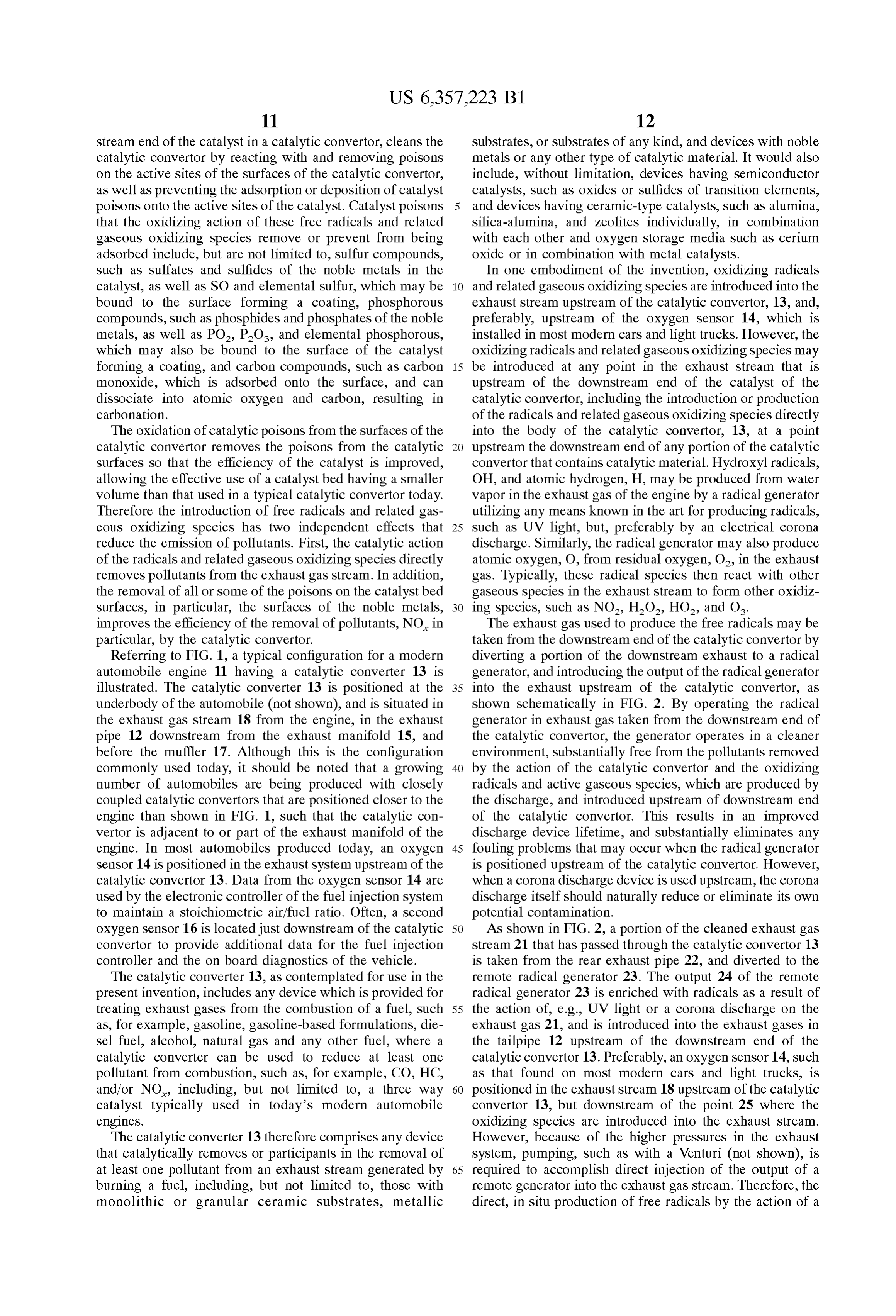
oxygen Sensor 16 is located just downstream of the catalytic 50 AS shown in FIG. 2, a portion of the cleaned exhaust gas convertor to provide additional data for the fuel injection Stream 21 that has passed through the catalytic convertor 13 controller and the on board diagnostics of the vehicle. is taken from the rear exhaust pipe 22, and diverted to the The catalytic converter 13, as contemplated for use in the remote radical generator 23. The output 24 of the remote present invention, includes any device which is provided for radical generator 23 is enriched with radicals as a result of treating exhaust gases from the combustion of a fuel, Such 55 the action of, e.g., UV light or a corona discharge on the as, for example, gasoline, gasoline-based formulations, die exhaust gas 21, and is introduced into the exhaust gases in Sel fuel, alcohol, natural gas and any other fuel, where a the tailpipe 12 upstream of the downstream end of the catalytic converter can be used to reduce at least one catalytic convertor 13. Preferably, an oxygen Sensor 14, Such pollutant from combustion, Such as, for example, CO, HC, as that found on most modern cars and light trucks, is and/or NO, including, but not limited to, a three way 60 positioned in the exhaust Stream 18 upstream of the catalytic catalyst typically used in today's modern automobile convertor 13, but downstream of the point 25 where the engines. oxidizing Species are introduced into the exhaust Stream. The catalytic converter 13 therefore comprises any device However, because of the higher preSSures in the exhaust that catalytically removes or participants in the removal of System, pumping, Such as with a Venturi (not shown), is at least one pollutant from an exhaust Stream generated by 65 required to accomplish direct injection of the output of a burning a fuel, including, but not limited to, those with remote generator into the exhaust gas Stream. Therefore, the monolithic or granular ceramic Substrates, metallic direct, in Situ production of free radicals by the action of a
Page 18
corona discharge on water vapor and residual oxygen in the discharge upstream of the point that the air enters the engine. exhaust Stream is the most preferred method. A drawback of the production or injection of the oxidizing Preferably, the radicals and related gaseous oxidizing Species in the intake manifold is that a significant fraction of Species are produced in the exhaust upstream of the down the highly chemically active Species may be destroyed in the Stream end of the catalytic convertor by a corona discharge combustion process, and only those active species that device, placed in either the main exhaust pipe or in a shunt reside in the crevice regions and at the walls of the com path in parallel with the main exhaust gas Stream, as shown bustion chamber can effectively survive, and enter into the in FIG. 3. As shown in FIG. 3, a corona discharge device 30 exhaust gas Stream. In contrast, generators that inject free is mounted in an exhaust shunt 31 in mount 32. The exhaust radical and gaseous molecular oxidizers directly into or shunt 31 allows a portion of the exhaust gas stream 18 to which create these species in the exhaust (postcombustion) gas Stream can more effectively deliver the active Species bypass a Section of the exhaust pipe 12, by exiting the into the exhaust stream where CO and HC need to be exhaust pipe 12 at a first point 35, typically upstream of the oxidized. Thus, the relative amount of radicals that must be catalytic convertor 13, and re-entering the exhaust pipe at a produced to provide a given amount of radicals at the Second point 36, which is also upstream of the catalytic catalytic convertor is significantly Smaller when the active convertor 13. The exhaust shunt may require a restrictive 15 Species are produced in or introduced into the exhaust gas orifice 33 or other device in the exhaust pipe to regulate or Stream than the amount required for other methods. This control the exhaust gas flow rate. Such a shunt path is useful directly translates into proportionally lower electrical input in that it allows the corona discharge device to be operated demands for the radical generator.
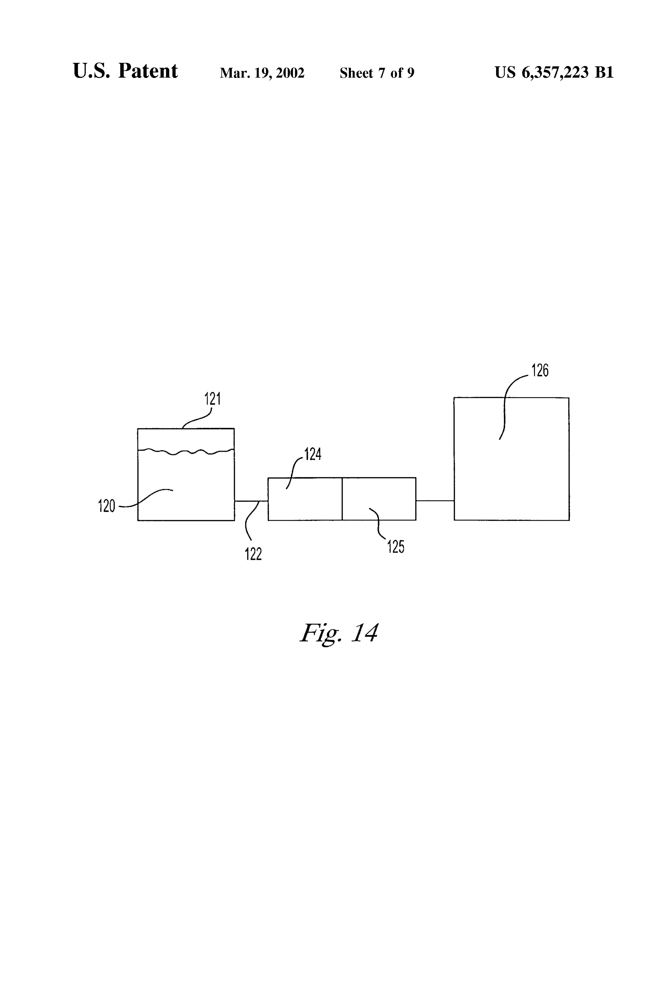
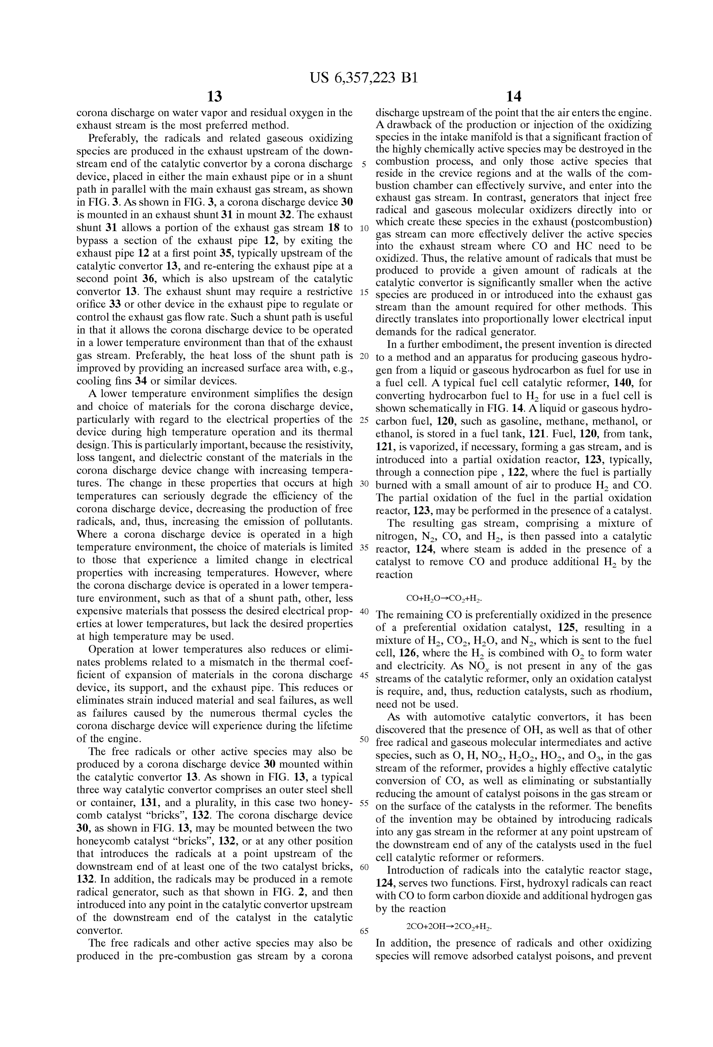
in a lower temperature environment than that of the exhaust In a further embodiment, the present invention is directed gas Stream. Preferably, the heat loSS of the Shunt path is to a method and an apparatus for producing gaseous hydro improved by providing an increased Surface area with, e.g., gen from a liquid or gaseous hydrocarbon as fuel for use in cooling fins 34 or Similar devices. a fuel cell. A typical fuel cell catalytic reformer, 140, for A lower temperature environment simplifies the design converting hydrocarbon fuel to H2 for use in a fuel cell is and choice of materials for the corona discharge device, shown Schematically in FIG. 14. A liquid or gaseous hydro particularly with regard to the electrical properties of the 25 carbon fuel, 120, Such as gasoline, methane, methanol, or device during high temperature operation and its thermal ethanol, is stored in a fuel tank, 121. Fuel, 120, from tank, design. This is particularly important, because the resistivity, 121, is vaporized, if necessary, forming a gas Stream, and is loSS tangent, and dielectric constant of the materials in the introduced into a partial oxidation reactor, 123, typically, corona discharge device change with increasing tempera through a connection pipe, 122, where the fuel is partially tures. The change in these properties that occurs at high burned with a small amount of air to produce H and CO. temperatures can Seriously degrade the efficiency of the The partial oxidation of the fuel in the partial oxidation corona discharge device, decreasing the production of free reactor, 123, may be performed in the presence of a catalyst. radicals, and, thus, increasing the emission of pollutants. The resulting gas Stream, comprising a mixture of Where a corona discharge device is operated in a high nitrogen, N, CO, and H, is then passed into a catalytic temperature environment, the choice of materials is limited 35 reactor, 124, where Steam is added in the presence of a to those that experience a limited change in electrical catalyst to remove CO and produce additional H. by the properties with increasing temperatures. However, where reaction the corona discharge device is operated in a lower tempera ture environment, Such as that of a shunt path, other, leSS expensive materials that possess the desired electrical prop 40 The remaining CO is preferentially oxidized in the presence erties at lower temperatures, but lack the desired properties of a preferential oxidation catalyst, 125, resulting in a at high temperature may be used. mixture of H., CO, HO, and N, which is sent to the fuel Operation at lower temperatures also reduces or elimi cell, 126, where the H is combined with O. to form water nateS problems related to a mismatch in the thermal coef and electricity. AS NO is not present in any of the gas ficient of expansion of materials in the corona discharge 45 Streams of the catalytic reformer, only an oxidation catalyst device, its Support, and the exhaust pipe. This reduces or is require, and, thus, reduction catalysts, Such as rhodium, eliminates Strain induced material and Seal failures, as well need not be used.
as failures caused by the numerous thermal cycles the AS with automotive catalytic convertors, it has been corona discharge device will experience during the lifetime discovered that the presence of OH, as well as that of other of the engine. 50 free radical and gaseous molecular intermediates and active
The free radicals or other active Species may also be Species, Such as O, H, NO2, H2O, HO, and O, in the gas produced by a corona discharge device 30 mounted within Stream of the reformer, provides a highly effective catalytic the catalytic convertor 13. As shown in FIG. 13, a typical conversion of CO, as well as eliminating or Substantially three way catalytic convertor comprises an outer Steel shell reducing the amount of catalyst poisons in the gas Stream or or container, 131, and a plurality, in this case two honey 55 on the surface of the catalysts in the reformer. The benefits comb catalyst “bricks”, 132. The corona discharge device of the invention may be obtained by introducing radicals 30, as shown in FIG. 13, may be mounted between the two into any gas Stream in the reformer at any point upstream of honeycomb catalyst “bricks”, 132, or at any other position the downstream end of any of the catalysts used in the fuel that introduces the radicals at a point upstream of the cell catalytic reformer or reformers.
downstream end of at least one of the two catalyst bricks, 60 Introduction of radicals into the catalytic reactor Stage, 132. In addition, the radicals may be produced in a remote 124, Serves two functions. First, hydroxyl radicals can react radical generator, Such as that shown in FIG. 2, and then with CO to form carbon dioxide and additional hydrogen gas introduced into any point in the catalytic convertor upstream by the reaction of the downstream end of the catalyst in the catalytic
COnVertOr. 65
The free radicals and other active Species may also be In addition, the presence of radicals and other oxidizing produced in the pre-combustion gas Stream by a corona Species will remove adsorbed catalyst poisons, and prevent
Page 19
the adsorption of catalyst poisons onto the Surface of the embodiments, in addition to operating at a temperature on catalyst, providing for better CO to CO conversion. The the order of about 800° C., the corona discharge device must addition of radicals to the preferential oxidation catalyst will meet automotive electromagnetic interference (EMI) convert CO to CO and H, and remove and prevent the requirements, be readily replaceable, and be capable of adsorption of poisons in the Same manner. withstanding thousands of thermal transients of about 800 However, because of the high reactivity of the oxidizing C., Such as those experienced during Start-up and cool down radicals and other active gaseous Species with hydrocarbon of an engine, as well as Several million Smaller thermal fuels, the radicals may be introduced into the partial oxida transients where the change in temperature may be on the tion reactor only when the hydrocarbon fuel is not present. order of about 200 C. In a preferred corona discharge Should the highly reactive radicals be introduced into the device, about 20 to about 50 W of high frequency, high partial oxidation reactor when fuel is present it is likely that Voltage power is required, i.e., from about 1,000 to about most of the radicals would be consumed by reaction with the 250,000 Hz and from about 5,000 to about 20,000 VAC. fuel, and, thus, the radicals would have little effect on However, under Some transient operating conditions, Such as catalyst poisons in this stage of the catalytic reformer. engine cold or warm Starts, more radical production may be Therefore, the radicals are preferably introduced into the 15 desired. In this case the corona device would require opera partial oxidation reactor only during a “cleanup' or “recov tion at higher power levels of up to 200 to 300 watts. This ery' cycle in which any catalyst poisons adsorbed onto a transient power condition can be met by increasing the catalyst in the catalytic reformer, in particular, any catalyst frequency Voltage product to the corona device by a factor used in the partial oxidation reactor, may be oxidized and of 5 to 10 for such periods, which typically range from about removed to clean and recover the catalyst. If a “cleanup’ or 30 to about 100 sec. This can be accomplished through “recovery cycle or mode is required, it may be desirable to proper corona unit high Voltage power System design, and provide a pair of catalytic reformers in parallel for a fuel cell the use of control signals from the engine controller or local that will be used on a substantially continuous basis. In this Startup temperature readings.
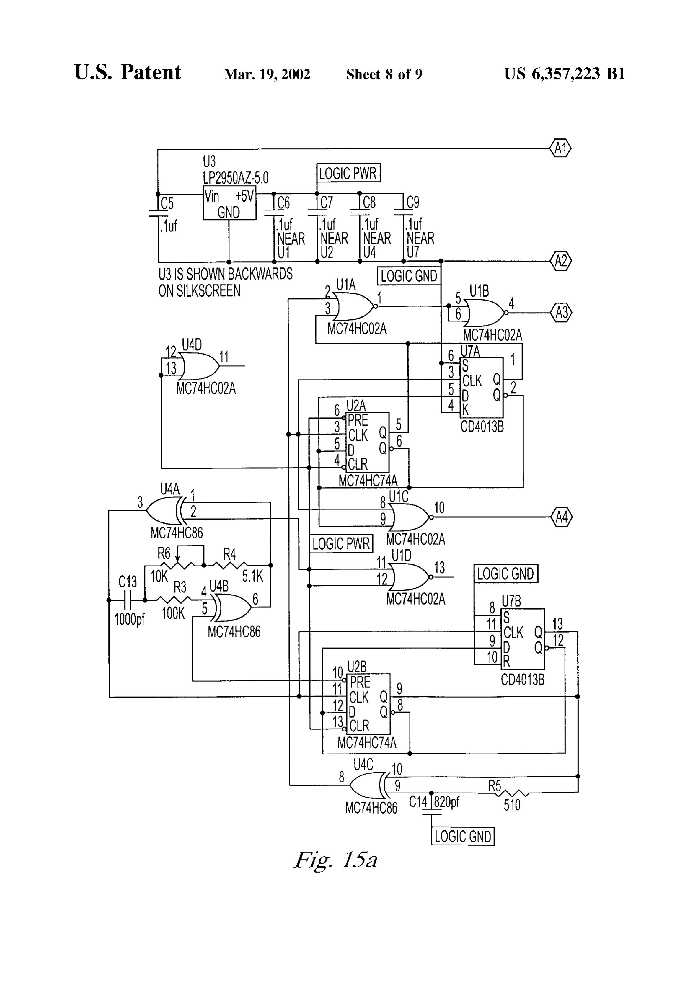
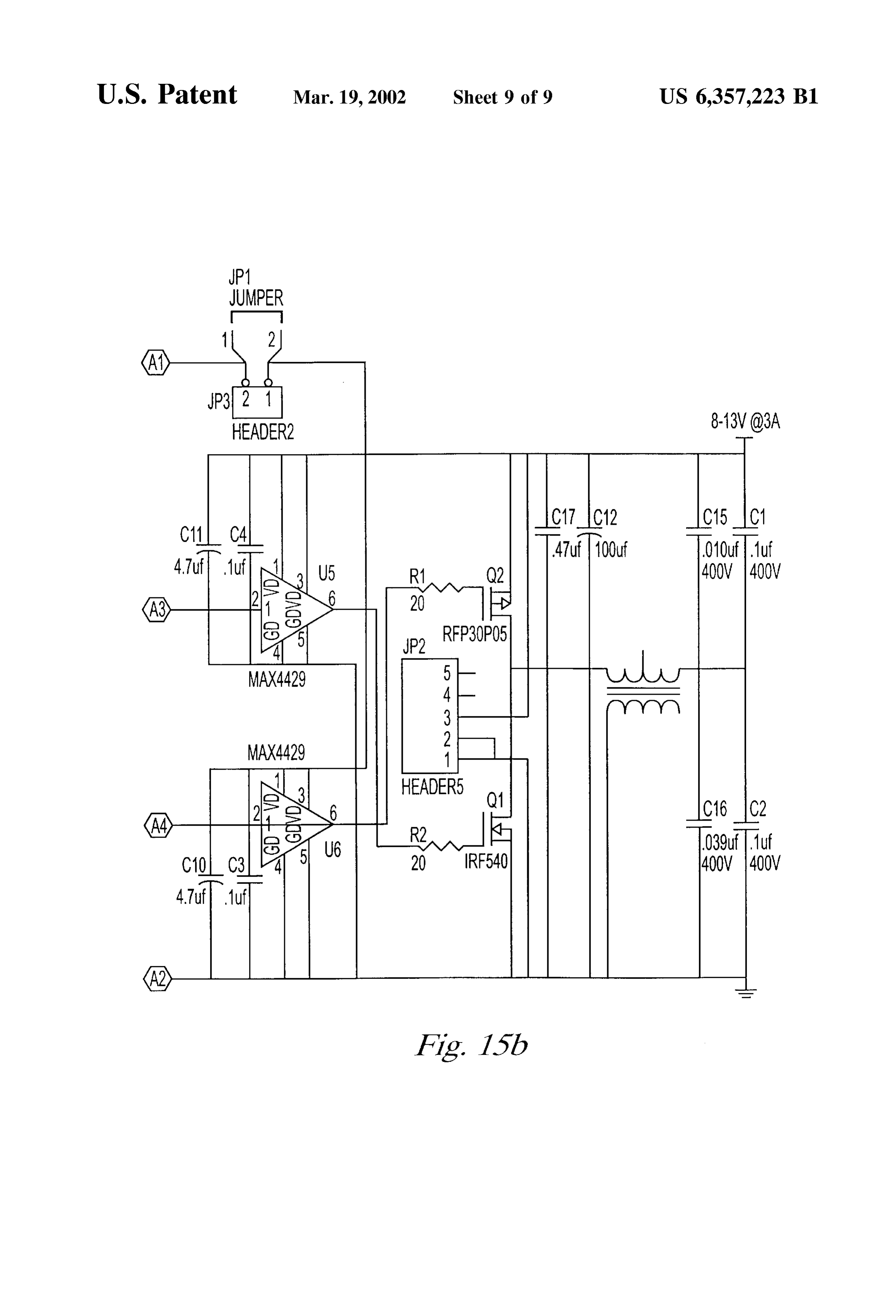
manner, one catalytic reformer may be used to provide An example of the circuitry for a power Supply useful hydrogen fuel for the fuel cell, while the second reformer is 25 with the present invention is shown in FIG. 15. The circuitry in the recovery mode. By cycling between reformers in this shown in FIG. 15 provides a resonant Switch-mode invertor manner, each reformer could always be operated with a capable of converting a 12 VDC nominal input Voltage to an minimum of catalyst poison adsorbed onto the catalyst. approximately 10 kVAC Sine wave output to drive a capaci However, it has also been discovered that the generation tive “silent discharge” device, Such as the corona discharge of radicals and related active gaseous species, and their device of the invention.
introduction into a gas Stream in the catalytic reformer Corona discharge devices useful in the invention include, upstream of the downstream end of a catalyst in either the but are not limited to, those having generally cylindrical catalytic reactor or the preferential Oxidation catalyst during Symmetry and, in most cases, at least two concentric elec operation of the catalytic reformer, cleans the catalyst in trodes. At least three general design alternatives for corona those Stages by reacting with and removing poisons on the 35 discharge devices that have generally cylindrical Symmetry active Sites of the Surfaces of the catalytic convertor, as well exist. These three general design alternatives are illustrated as preventing the adsorption or deposition of catalyst poi in FIGS. 4, 5, and 6. FIG. 4 is a cross-section of a cylindrical Sons onto the active Sites of the catalyst. corona discharge device 40 having concentric cylindrical AS with automotive applications of the invention, electrodes inner electrode 41 and outer electrode 42. The hydroxyl radicals, OH, and atomic hydrogen, H, are pro 40 device 40 typically includes a ferrule 44 in the base 47, duced from water vapor in a gas Stream of the catalytic which provides a gas Seal, and threads 46 or other means for reformer. The radicals may be formed by a radical generator mounting the device 40 in the exhaust pipe 12 or shunt 31. utilizing any means known in the art for producing radicals, The inner electrode 41 is surrounded by a dielectric layer 43, Such as UV light, but, preferably by an electrical corona which prevents breakdown, and maintains the corona dis discharge. Similarly, the radical generator may also produce 45 charge. It is important for the overall efficiency of the device atomic oxygen, O, from residual oxygen, O, in the exhaust to have the predominant Voltage across the "air gap 45 of gas. Typically, these radical Species then react with other the device. Because the dielectric layer 43 in the corona gaseous Species in the exhaust Stream to form other oxidiz discharge device shown in FIG. 4 is located in a region ing species, Such as NO, HO, HO, and O. Where the where high electric fields occur, most of the Voltage is acroSS radicals are produced during the operation of the catalytic 50 the “air gap of the corona discharge device, and the reformer, it is preferred that the radicals be produced in at efficiency of the device is maintained. least one of the catalytic reactor, the preferential oxidation However, depending on the design of the corona dis reactor, or within a gas Stream Supplying air or water vapor charge device, the dielectric, due to its conductivity, may act to at least one of the catalytic reactor or the preferential as a shunt conductive path to ground that effectively reduces oxidation reactor. AS with the automotive applications, it is 55 the current to the corona discharge. Where the corona preferred that the radicals be produced with a corona dis discharge device is Subject to shunt capacitive losses in the charge device of the type described below. region of the base 47 that increase proportionally with A corona discharge device for use with the invention increasing dielectric constant, a decision is often required should preferably be capable of functioning for at least about during the design of a corona discharge device of this type, 3,000 to about 4,000 hours in the high temperature envi 60 as to the relative importance of the Voltage drop across the ronment of the exhaust Stream of an internal combustion dielectric and the shunt capacitive losses in the base region. engine before replacement is required. Because of Space In practice, the careful design of the corona discharge device limitations in modern automobiles and in applications using will minimize the effective area of the shunt capacitance, fuel cells, it is preferred that the corona discharge device and provide a low dielectric constant. have a Small physical volume, i.e., on the order of the size 65 Resistive losses also occur in dielectrics at high of a typical Spark plug, and require a power Supply that is no temperatures, and, thus, a dielectric material must be larger than about 300 to about 400 cubic cm. In certain Selected in which the resistive losses are acceptably low, or
Page 20
the corona discharge device must be operated in a chamber can be provided through controlled injection of air, either by or shunt path off of the exhaust System to allow operation at Self pumping, Such as through the pumping action of a a lower temperature. Other design issues include EMI, Venturi Section in the exhaust pipe, or by an upstream air resistance to corrosion in the corrosive, high temperature pump. With a Venturi, a fast acting valve, Such as an environment, contamination, condensation of water during electro-mechanical valve or a valve based on MEMS (Micro engine cool down, and vibration. For EMI, the corona Mechanical-Electronic Systems) technology would be discharge device and its power Supply and leads must have required to terminate the air injection after the cold Start Sufficient shielding to meet automotive System EMI require period was complete. The rate of air injection is limited with mentS. a Venturi, and, thus, only partial combustion of residual fuel Material Selection should be based on high temperature is possible with Venturi pumping. However, an air pump is behavior and the ability to withstand a corrosive environ not Subject to Such a limitation, and can provide Sufficient air ment that could limit the design life or performance of the for complete combustion of any residual fuel in the exhaust device, e.g., high temperature diffusion of contaminants into gas Stream.
the dielectric that could lower the resistivity of the dielectric Where the ignition of exhaust gases by the corona dis below the required value for maximum efficiency, and 15 charge is desired, it may also be desirable to use flame possibly result in the formation of a partial or complete short arresters, Such as wire Screen to control or limit the regions circuit in the device. However, the corona discharge itself of the exhaust Stream in which corona assisted combustion should naturally reduce or eliminate contamination of the could occur to any of, e.g., upstream of the corona discharge device. device, downstream of the device, both upstream and down The need for a high dielectric constant can be reduced or Stream of the device, or in a limited Volume in and around eliminated by placing the dielectric layer 43 on the inner the corona discharge device.
Surface of the outer electrode 42. Such a device 50 is Corona discharge devices useful in the present invention illustrated in FIG. 5. Because the electric fields that occur in may be of any type that produces a corona Sufficient to form the region of the outer electrode 42 are relatively low an effective amount of active chemical Species, Such as compared to those in the region of the center electrode 41, 25 hydroxyl radical. For example, representative corona dis a dielectric material having a lower dielectric constant may charge devices, such as those shown in FIG. 4 and FIG. 5, be used for the dielectric layer. This reduces shunt capacitive may be modified Sparkplug-like devices, having a Small losses, while maintaining a limited Voltage drop acroSS the center electrode 41 with a diameter of about 0.1 to about 0.3 dielectric layer. cm. The inner electrode 41, is inserted into and held in place It is also possible to use, for example, the exhaust pipe 12 by a hole in the dielectric layer 43 in the base 47. In devices or exhaust shunt 31 as a distant ground for the corona where the dielectric layer 43 is positioned on the inner discharge device, eliminating the need for an outer elec surface of the outer electrode 42, the dielectric layer 43 trode. Such a distant ground corona discharge device 60 is basically forms a cup having a hole in its base to position the shown in FIG. 6, and only requires an inner electrode 41, inner electrode. The outer electrode has an inner diameter of preferably, with a sharp or Small radius tip to promote 35 about 1 to about 2 cm and a length of about 1.5 to 3 cm. The breakdown, a dielectric insulator 43, and a base 47, which dielectric layer has a base and wall thickness of about 1 to typically includes a ferrule 44 to provide the required Seal about 3 mm, which is chosen to provide the desired dielec and Strain relief. Because a distant ground device is only tric Strength at the operating Voltage of the corona discharge Subject to base loSS considerations, Such a device also allows device.
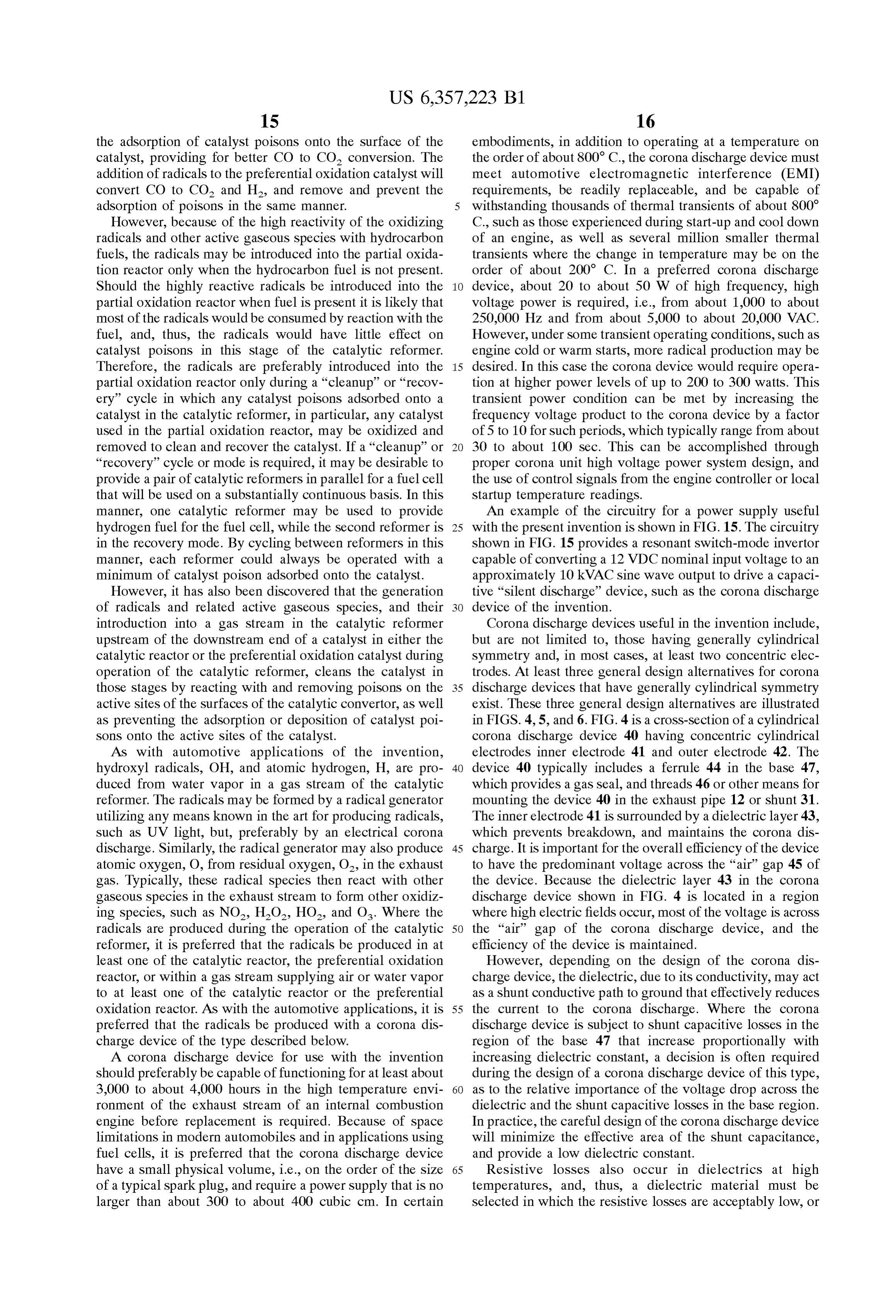
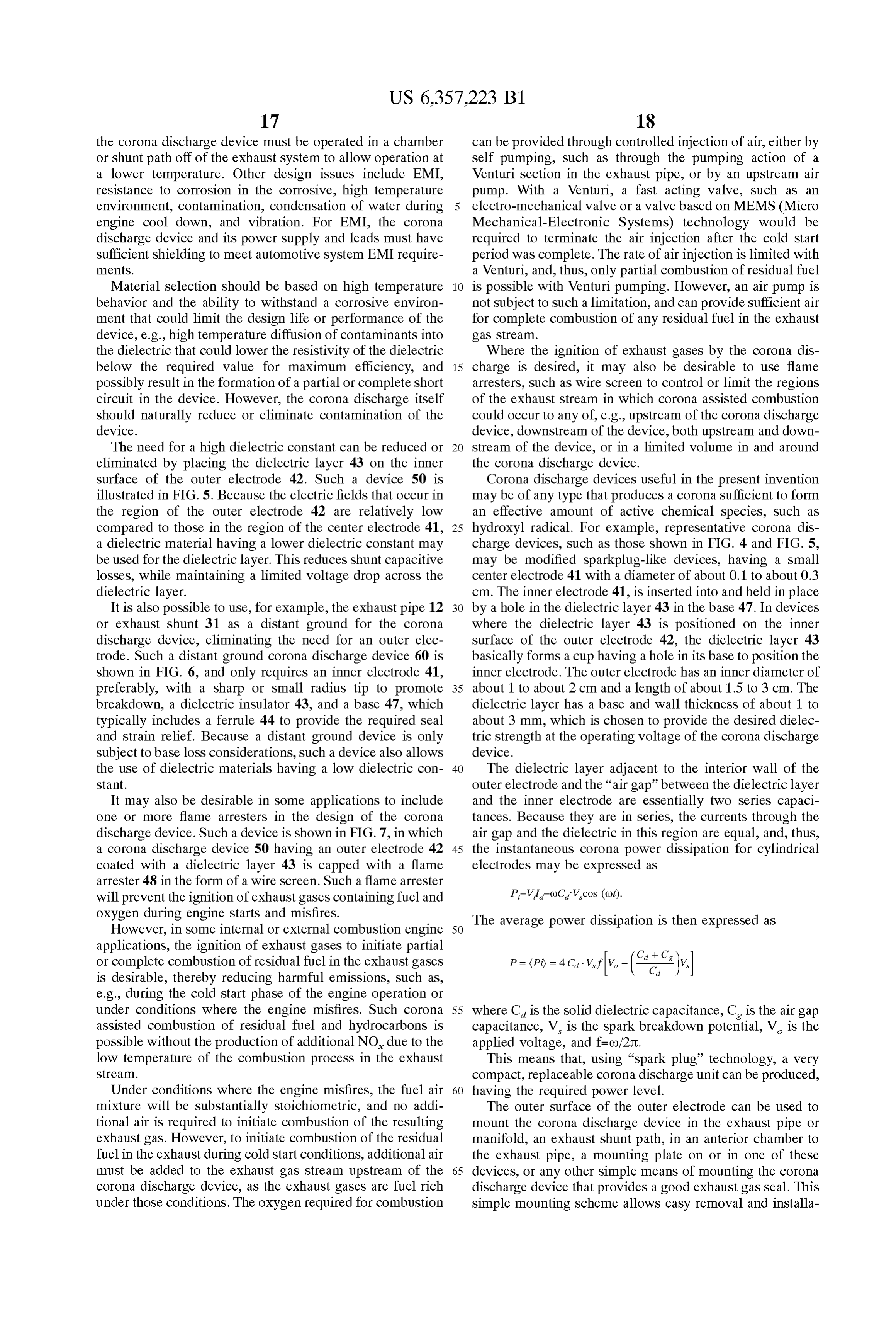
the use of dielectric materials having a low dielectric con 40 The dielectric layer adjacent to the interior wall of the Stant. outer electrode and the “air gap' between the dielectric layer It may also be desirable in Some applications to include and the inner electrode are essentially two Series capaci one or more flame arresters in the design of the corona tances. Because they are in Series, the currents through the discharge device. Such a device is shown in FIG. 7, in which air gap and the dielectric in this region are equal, and, thus, a corona discharge device 50 having an Outer electrode 42 45 the instantaneous corona power dissipation for cylindrical coated with a dielectric layer 43 is capped with a flame electrodes may be expressed as arrester 48 in the form of a wire Screen. Such a flame arrester will prevent the ignition of exhaust gases containing fuel and P=VI =(OC, Vcos (ot).
oxygen during engine Starts and misfires. The average power dissipation is then expressed as However, in Some internal or external combustion engine 50 applications, the ignition of exhaust gases to initiate partial or complete combustion of residual fuel in the exhaust gases P = (Pi) = 4 C. V. V. (i. v. is desirable, thereby reducing harmful emissions, Such as, e.g., during the cold Start phase of the engine operation or under conditions where the engine misfires. Such corona 55 where C is the Solid dielectric capacitance, C is the air gap assisted combustion of residual fuel and hydrocarbons is capacitance, V is the Spark breakdown potential, V is the possible without the production of additional NO due to the applied Voltage, and f=()/2t.
low temperature of the combustion process in the exhaust This means that, using “spark plug technology, a very Stream. compact, replaceable corona discharge unit can be produced, Under conditions where the engine misfires, the fuel air 60 having the required power level.
mixture will be Substantially Stoichiometric, and no addi The outer Surface of the outer electrode can be used to tional air is required to initiate combustion of the resulting mount the corona discharge device in the exhaust pipe or exhaust gas. However, to initiate combustion of the residual manifold, an exhaust shunt path, in an anterior chamber to fuel in the exhaust during cold Start conditions, additional air the exhaust pipe, a mounting plate on or in one of these must be added to the exhaust gas Stream upstream of the 65 devices, or any other simple means of mounting the corona corona discharge device, as the exhaust gases are fuel rich discharge device that provides a good exhaust gas Seal. This under those conditions. The oxygen required for combustion Simple mounting Scheme allows easy removal and installa
Page 21
tion of the corona discharge device in the exhaust System, A typical compact discharge device 80 may have an outer and with a shunt path or slight receSS in the exhaust System electrode 83 with a length of about 1 to about 2 cm, represents little or no interference to the main exhaust flow. preferably about 1.5 cm, and an inner electrode 82 with a In each case, the corona discharge device is placed in the length of about 4 to about 8 cm, preferably about 5 to about exhaust gas of the engine, So that the desired free radicals are 7 cm, most preferably about 6 cm. The dielectric insulator 81 produced directly from water vapor, residual oxygen, and of Such a device can be constructed from a ceramic material other constituents of the exhaust gas. Such as Fosterite, and will have a diameter of about 0.7 to The condensation of water during cool down could result about 1.3 cm, preferably about 1 cm, a length of about 3 to in a short out of the corona discharge device, and, thus, the about 5 cm, preferably about 4 cm, and a thickness of about device is preferably mounted in the top of the exhaust pipe, 0.1 to about 0.2 cm, preferably about 0.15 cm, can be used So that the electrodes face down, minimizing the exposure to at a temperature of up to about 900 C. with resistive power water during those times when the temperature is too low to losses drive off any water. In addition, vibration problems may be voltageofofless than about 10% at a maximum operating at least about 5,000 V. In a relatively low avoided by designing the device and its power Supply and wiring to have natural resonant frequencies well above 15 temperature environment, Such as that in an exhaust shunt, automobile vibrational frequencies. and because of the temperature variation along the ceramic AS discussed above, the resistive and capacitive shunt dielectric insulator 81, an even higher operating Voltage is losses of the dielectric layer used to provide an insulating possible, while maintaining an acceptable power loss. A Support between the two electrodes of a corona discharge corona discharge device of this design would provide about device are a major consideration in the design of Such a 30 to about 50W of power operating at a frequency of about device. Any reduction in shunt capacitance allows operation 100 kHz. However, under some transient operating of the discharge at higher frequencies at a given capacitive conditions, Such as engine cold or warm starts, more radical power loSS, and, according to basic design principles for a production may be desired. In this case, the corona device corona device having a power output proportional to the would require operation at higher power levels of up to 200 frequency of the applied Voltage, would allow a more to 300 watts. This transient power condition can be met by compact design. A more compact design is advantageous in 25 increasing the frequency Voltage product to the corona that it allows the use of a Smaller corona gap, which, in turn, device by a factor of 5 to 10 for such periods, which results in a lower breakdown Voltage acroSS the gap, and, typically range from about 30 to 100 sec. This can be thus, allows the use of a lower operating Voltage. The lower accomplished through proper corona unit high Voltage operating Voltage results in lower resistive and capacitive power System design and the use of control Signals from the losses, increasing the efficiency of the corona discharge engine controller or local Startup temperature readings. The device. The Smaller, more efficient corona discharge device long insulating path and thin walls of the insulator 81, will thus require a Smaller power Supply, which is a major minimize the capacitive shunt losses to less than about 10%, advantage in modern Vehicles where Space is at a premium. even for insulators having a dielectric constant of more than A representative design for Such a compact corona dis 10 at operating frequencies on the order of about 100 kHz. charge device is shown in FIG. 8. FIG. 8 illustrates the 35 Such a high operating frequency allows the use of a very physical components of an efficient compact corona dis compact high Voltage power Supply.
charge device 80, as well as the important device operating AS discussed above, the expression for the power dissi and device design regions. The illustration, as well as the pation in a corona is given by dimensions given below, is merely representative of a generic design, and one of ordinary skill in the art will 40 recognize that many variants that fall within the Scope of the where C, and C are respectively the capacitance of the general design principles illustrated and discussed here. dielectric and the gap in the corona region, V and V are The key features of the embodiment illustrated in FIG. 8 respectively the Spark breakdown voltage of the gap and the include a long, thin-walled dielectric insulator 81 that, along applied Voltage to the corona device, and f is the frequency with the proper Selection of materials, provides a path of 45 of the Voltage applied to the device. Taking values of these high resistance between the inner 82 and outer 83 electrodes quantities of as V=5,000 V, V-3,000 V, C=6x10' farad, that are supported by the insulator 81. A thin metal cap 84 C=1x10' farad; then at a frequency of 3x10 Hz, the is provided as a gas Seal. The inner electrode 82 may be power in the corona is about 27 W. The output can be scaled substantially longer than the outer electrode 83. In one such by frequency, applied Voltage, or capacitance (primarily the embodiment, the inner electrode 82 typically has a length 50 length of the corona discharge region). The output can be that is at least about twice that of the outer electrode 83, and, controlled by the frequency and/or Voltage of the corona preferably, at least about 4 times the length of the outer device power Source.
electrode 83, and the length of the inner electrode 82 is The Spark breakdown voltage is almost directly propor typically about at least about 4 times, preferably at least tional to the density of the exhaust gas in the corona gap about 6 times, the diameter of the corona discharge device 55 region, which is almost directly proportional to the tempera 80, as determined from the diameter of the dielectric insu ture in the gap region. This breakdown Voltage will vary in lator 81. The outer electrode 83 is mechanically and elec proportion to the temperature of the gas in the corona unit, trically connected to the base 85 of the compact corona and, therefore, its operating temperature. If, for example, the discharge device 80, where the base includes threads 86 or design were Such that the gas temperature in the corona unit other Similar mounting means to mount the device 80, Such 60 were half of the exhaust temperature, then the lower break that exhaust gases may enter into the air gap 89. As a result down voltage would increase to 6,000 V. of the difference in the length of the inner and outer FIGS. 9 and 10 show two design variants on the above electrodes 82 and 83, the air gap 89 is divided into a corona design. In FIG. 9 the skirt section 91 is lengthened and discharge region 87, i.e., that part of the air gap 89 where the extended Surfaces 92 are employed to augment heat inner and outer electrodes overlap, and a lullage Volume 88, 65 eXchange to the ambient environment. The longer conduc i.e., that portion of the air gap 89 that extends from the outer tion path along with the heat eXchangers provide for cooler electrode 83 to the metal cap 84. operation of the dielectric material 81 in particular, thus
Page 22
providing for a wider Selection of materials or better per now be obvious to those skilled in that art, and, therefore, the formance for this application with Satisfactory resistance and scope of the invention should not be limited by the specific capacitance at the resulting operating temperature. It has disclosure herein, but only by the appended claims. also been observed in tests that the injection of small What is claimed:
amounts of air (<10 cc/sec) in a manner that modifies the 1. An apparatus for enhancing the rate of a chemical engine Stoichiometry to permit the operation of the catalyst reaction in a gas Stream of a mobile vehicle, the apparatus at a desired equivalence ration, e.g., by injecting air comprising:
upstream of the engine Side oxygen Sensor, results in no a passageway for channeling the gas stream; adverse engine performance or engine/catalyst emission at least one device for producing radicals or other active performance. In FIG. 10 a pumping action is provided by the Species from at least one of water vapor or other low pressure produced in a Venturi section 95 added to the gaseous Species present in the gas Stream located in the exhaust system 96. This low pressure in conjunction with the passageWay, orifice 97 in the metal cap 84 of the compact corona a power Supply including a Switch-mode inverter capable discharge device 80 provides for an air flow of less than of converting DC input into AC output, the power about 10 cc/sec, which limits the temperature, cooling the 15 Supply adapted and configured to provide electrical ceramic dielectric Section of the corona device, and aids in power having a frequency of at least about 1,000 Hz to the injection of radicals generated in the corona discharge. the at least one device; and Under normal operating conditions, the engine produces at least one heterogenous catalyst having an upstream end exhaust gas pressure oscillations having a frequency of and a downstream end, and at least one Surface having about 30 to about 100 Hz and a peak to peak variation of a plurality of catalytically active Sites on the Surface positioned in the passageway Such that at least a portion about 20 to about 80%, depending upon the location in the of the heterogenous catalyst is located downstream exhaust System. These pressure oscillations in conjunction from the at least one device and at least a portion of the with the ullage volume 88 provide an effective, continuous gas Stream is exposed to the at least one device prior to pumping action of the radicals and other species produced in the downstream end of the heterogenous catalyst. the corona discharge into the exhaust Stream. The pumping 25 2. The apparatus according to claim 1, further comprising effect of the exhaust gas pumping OScillations for any of the at least one Sensor for monitoring the gas Stream located corona discharge devices described above, where the dis downstream from the downstream end of the heterogenous charge device 110 is installed at a point on the exhaust pipe catalyst.
112 where the oscillations occur, in the manner shown in 3. The apparatus according to claim 2, wherein the power FIG. 11, where the discharge device 110 is mounted on a Supply is adapted and configured to provide electrical power simple “T” 113 off the side of the exhaust pipe 112. The of variable current and Voltage.
pumping effect and the total gas motion can be augmented 4. The apparatus according to claim 3, further comprising with a plenum 114 as shown in FIGS. 12a and 12b. As a feedback loop connecting the at least one sensor to the shown in FIG. 12a, the plenum 114 may be a separate vehicle's onboard diagnostics.
extension of the exhaust pipe that is adjacent to the corona 35 5. The apparatus according to claim 1, wherein the discharge device. Alternatively, the plenum 114 may be radicals or other active Species are introduced in an amount incorporated into the corona discharge device, as shown in Sufficient to reduce or eliminate poisoning of the catalyst by catalyst poisons.
FIG.12b, such that high pressure oscillations in the exhaust 6. The apparatus according to claim 5, wherein the force a portion of the exhaust gas past the corona discharge catalyst poison is at least one of the group consisting of into the plenum, and low pressure oscillations in the exhaust 40 Sulfur, a Sulfur containing compound, phosphorous, a phos force exhaust result in the exhaust gas in the plenum phorous containing compound, carbon and a carbon con returning to the main exhaust gas Stream enriched with taining compound.
radicals and other active species. In addition, cooling fins 7. The apparatus according to claim 1, wherein the gas 116 may be added to lower the operating temperature for the Stream is an exhaust Stream from an internal combustion discharge device 110. AS noted above, a cooler operating 45 engine.
environment improves the efficiency of the corona dis 8. The apparatus according to claim 7, wherein the charge. internal combustion engine is a Spark ignition engine. It should be noted that the only requirement of the 9. The apparatus according to claim 7, wherein the preceding embodiments of the present invention is that free internal combustion engine is a diesel engine. radicals or gaseous and active oxidizing Species, in 50 10. The apparatus according to claim 1, wherein the at particular, hydroxyl radical, are added to the combustion gas least one device, comprises,
Stream at a point upstream of or at the catalytic converter, for at least one first electrode, example, the air intake duct to the carburetor or fuel at least one Second electrode; and injection Systems of the combustion chamber, the air/fuel at least one dielectric positioned between the first and intake manifold to the combustion chamber, the combustion 55 Second electrodes.
chamber directly or the exhaust manifold of the combustion 11. The apparatus according to claim 10, wherein the at chamber, or the exhaust pipe. least one Second electrode is concentric about the at least one Moreover, while the present invention has been described first electrode.
in one embodiment with reference to a catalytic converter, it 12. The apparatus according to claim 10, wherein the is contemplated that only the high Surface area provided by 60 dielectric is a layer on either the first or Second electrode. those catalysts in conjunction with the introduction of 13. The apparatus according to claim 1 adapted and hydroxyl radicals and other active Species would be required configured Such that no additional reducing agent is added to to reduce the pollutants in the exhaust gases of a combustion the gas Stream.
engine. 14. The apparatus according to claim 1, wherein the at Although the present invention has been described with 65 least one device and the at least one heterogenous catalyst particular reference to its preferred embodiments, it should are separated by a pre-determined distance in the passage be understood that many variations and modifications will way.
Page 23
15. The apparatus according to claim 1, wherein the wherein the apparatus is adapted and configured Such that heterogenous catalyst is a three-way catalyst. no additional reducing agent is added to the exhaust gas 16. The apparatus according to claim 1, wherein the Stream.
heterogenous catalyst is a ceramic or Zeolite catalyst. 20. An apparatus for enhancing the rate of a chemical 17. The apparatus according to claim 1, further compris 5 reaction in an exhaust gas Stream containing exhaust gases ing a particulate trap located in the passageway. of a mobile vehicle, the apparatus comprising: 18. The apparatus according to claim 17, wherein the a passageway for channeling the gas stream; device is continuously powered whenever the internal com at least one device for producing radicals or other active bustion engine is operating. Species from at least one of water vapor or other 19. An apparatus for enhancing the rate of a chemical gaseous Species present in the gas Stream located in the reaction in an exhaust gas Stream containing exhaust gases passageway, wherein the device is adapted and config of a mobile vehicle, the apparatus comprising: ured to produce the radicals or other active species a passageway for channeling the gas Stream; Substantially whenever the mobile vehicle is producing the exhaust gases, at least one device for producing radicals or other active 15 a power Supply including a Switch-mode inverter capable Species from at least one of water vapor or other of converting DC input into AC output, the power gaseous Species present in the gas Stream located in the Supply adapted and configured to provide electrical passageway, wherein the device is adapted and config power having a frequency of at least about 1,000 Hz to ured to produce the radicals or other active species the at least one device;
Substantially whenever the mobile vehicle is producing at least one heterogenous catalyst having an upstream end the exhaust gases, and a downstream end, and at least one Surface having a power Supply including a Switch-mode inverter capable a plurality of catalytically active Sites on the Surface of converting DC input into AC output, the power positioned in the passageway Such that at least a portion Supply adapted and configured to provide electrical of the heterogenous catalyst is located downstream power having a frequency of at least about 1,000 Hz to 25 from the at least one device and at least a portion of the the at least one device; and gas Stream is exposed to the at least one device prior to at least one heterogenous catalyst having an upstream end the downstream end of the heterogenous catalyst; and and a downstream end, and at least one Surface having at least one Sensor for monitoring the exhaust gas Stream a plurality of catalytically active Sites on the Surface located downstream from the downstream end of the positioned in the passageway Such that at least a portion heterogenous catalyst, wherein the apparatus is adapted of the heterogenous catalyst is located downstream and configured Such that no additional reducing agent from the at least one device and at least a portion of the is added to the exhaust gas Stream. gas stream is exposed to the at least one device prior to the downstream end of the heterogenous catalyst,
Provenance
- Collection
- Cited prior art
- Original PDF
- patentimages.storage.googleapis.com →
- Filed
- 2000-02-18
- Pages
- 23
- Method
- pdftotext (the PDF's own text layer) + pdftoppm 300dpi page scans
- Source
- Google Patents bibliographic record
- Granted
- 2002-03-19
- Inventors
- Robert P. Caren; David Christeller; Jack A. Ekchian; Litex Inc
- Transcribed from
- patentimages.storage.googleapis.com →