(Va)
(Va)
Where it is first named
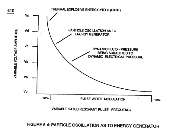
… applied traveling voltage wave-form (57) of Figure (6-2) of opposite electrical polarity (E9-66/ ElO-67) initiates the voltage-triggering process (600) of Figure (6-3) once maximum voltage deflection (VO - Va - Vb - Vc - Vn) of Figure (6-4) is achieved at Activation-Point (E9d) of Figure (6-2) ... releasing thermal Explosive Energy (gtnt) from the atomic level of the water molecule.
How it is written
- (VO - Va - Vb - Vc - Vn) 1× with (Vo) Applied Voltage Amplitude, (Vb) VIC Voltage Enhancement Circuit, (VC) Vacuum Gap, (Vn) Voltage Potential
- (Vo - Va -Vb - Vn) 1× with (Vo) Applied Voltage Amplitude, (Vb) VIC Voltage Enhancement Circuit, (Vn) Voltage Potential
Drawings 6
-
610 of Figure 6-4 · In Application of Usage
-
Figure (6-4) · In Application of Usage
-
The figure it sits on · WFC 425 - Illustrations
-
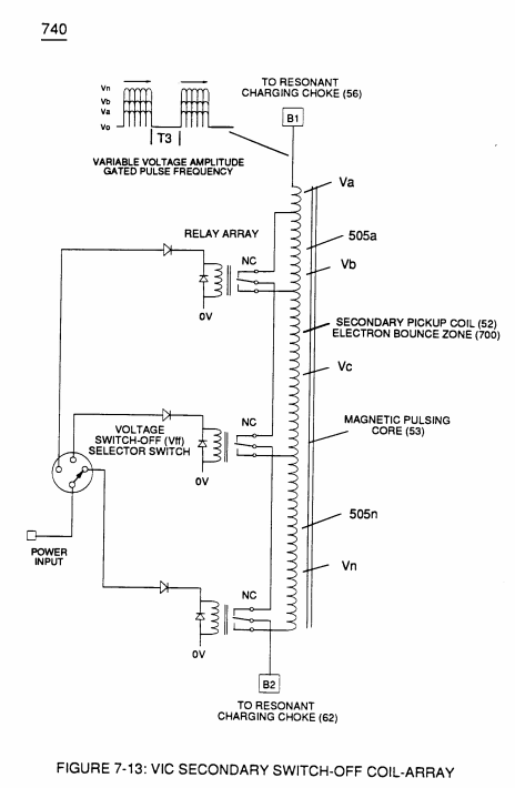
Figure (7-13) · Inductance (FL)
-
(see 740 of Figure 7-13) · Voltage Amplitude Switch-Off
-
The figure it sits on · WFC 426 - Illustrations
Where it is named · 2
In Application of Usage 1×
-
… applied traveling voltage wave-form (57) of Figure (6-2) of opposite electrical polarity (E9-66/ ElO-67) initiates the voltage-triggering process (600) of Figure (6-3) once maximum voltage deflection (VO - Va - Vb - Vc - Vn) of Figure (6-4) is achieved at Activation-Point (E9d) of Figure (6-2) ... releasing thermal Explosive Energy (gtnt) from the atomic level of the water molecule.
Inductance (FL) 1×
-
Component Interaction promotes Component Reactance during D.C. pulsing operations while allowing variable voltage amplitude (Vo - Va -Vb - Vn) of Figure (7-13) to be attenuated independently of Voltage Pulse frequency (49a xxx 49n), as so illustrated in (600) of Figure (6-3).