patent · US6314919B1
Method for preparing an air-fuel mixture for an internal combustion engine, device for realizing the same and heat-exchanger
13 November 2001
Page 1 — bibliographic record
(12) United States Patent (10) Patent No.: US 6,314,919 B1 Pugachev (45) Date of Patent: Nov. 13, 2001
(54) METHOD FOR PREPARING AN AIR-FUEL FOREIGN PATENT DOCUMENTS
MIXTURE FOR AN INTERNAL
COMBUSTION ENGINE, DEVICE FOR 24 08 462 8/1975 (DE). REALIZING THE SAME AND HEAT 26 13348 7/1980 (DE).
EXCHANGER
(76) Inventor: Alexandr Vasilevich Pugachev, ul.
D. Davydova, d.3, kV. 101, Moscow (List continued on next page.) (RU), 121170 Primary Examiner Willis R. Wolfe
ASSistant Examiner-Benton Jason (*) Notice: Subject to any disclaimer, the term of this patent is extended or adjusted under 35 (57) ABSTRACT
U.S.C. 154(b) by 0 days. The present invention pertains to the field of engine con (21) Appl. No.: 09/424,389 Struction and may be used in the inlet Systems of internal combustion engines for processing a portion of the rich (22) PCT Filed: Mar. 22, 1999 air-fuel mixture fed into the main flow, wherein the liquid (86) PCT No.: PCT/RU99/00087 fuel is pulverised and converted into gas. The purpose of this invention is to increase fuel Savings, to reduce the exhaust
S371 Date: Nov. 23, 1999 gas toxicity and to enable the use of a cheaper low-octane S 102(e) Date: Nov. 23, 1999 fuel. The method for preparing the air-fuel mixture com prises using the heat from the hot gases produced for heating (87) PCT Pub. No.: WO98/49204 the excessively rich mixture flow that contains between 10 and 100% of petrol to be used by the engine, wherein said
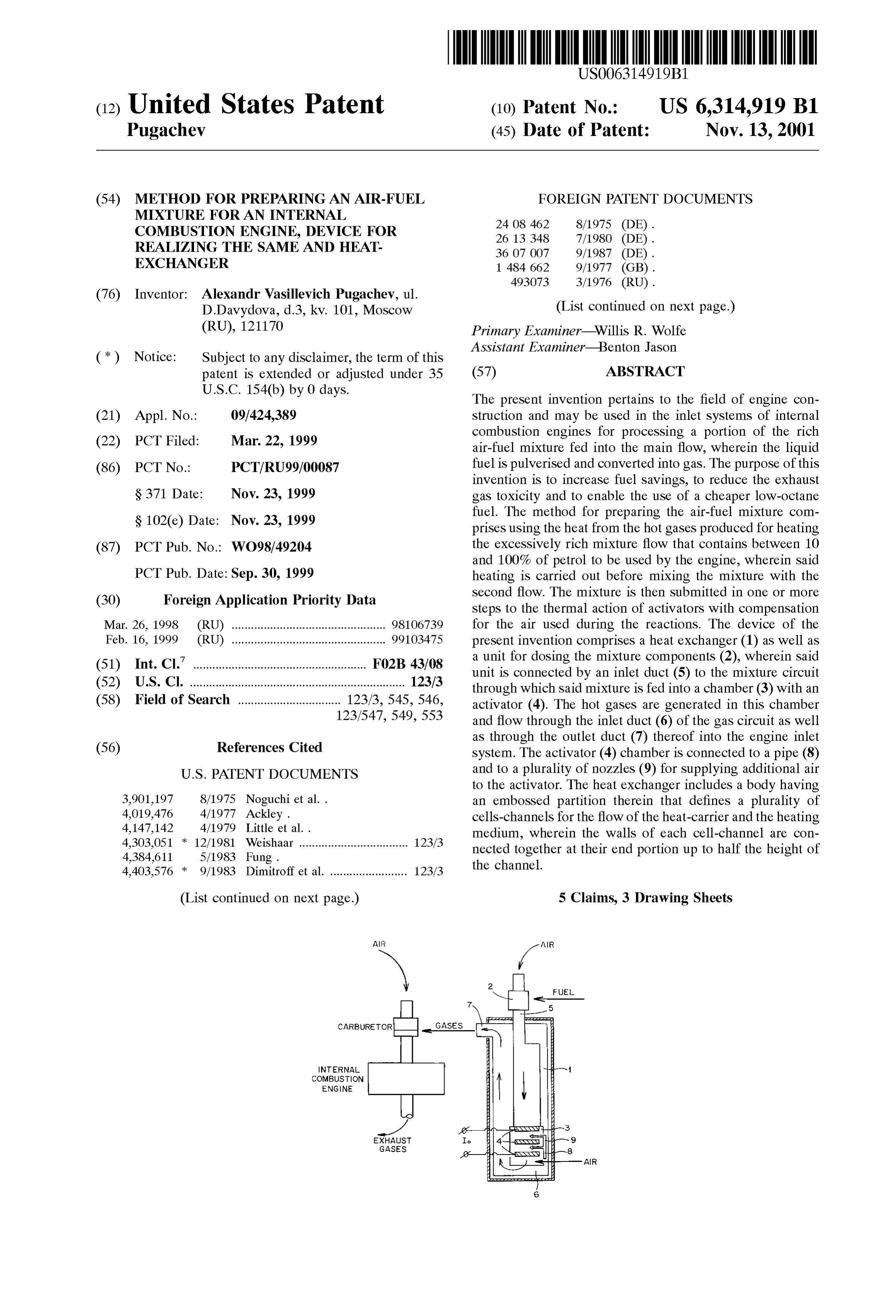
PCT Pub. Date: Sep. 30, 1999 heating is carried out before mixing the mixture with the Second flow. The mixture is then Submitted in one or more (30) Foreign Application Priority Data Steps to the thermal action of activators with compensation Mar. 26, 1998 (RU) ................................................ 98106739 for the air used during the reactions. The device of the Feb. 16, 1999 (RU) ................................................ 99.103475 present invention comprises a heat exchanger (1) as well as (51) Int. Cl." ............................................ FO2B 43/08 a unit for dosing the mixture components (2), wherein said (52) U.S. Cl. ................................................................... 123/3 unit is connected by an inlet duct (5) to the mixture circuit through which said mixture is fed into a chamber (3) with an (58) Field of Search ................................ 123/3, 545, 546, activator (4). The hot gases are generated in this chamber 123/547,549, 553 and flow through the inlet duct (6) of the gas circuit as well
as through the outlet duct (7) thereof into the engine inlet
System. The activator (4) chamber is connected to a pipe (8)
to the activator. The heat eXchanger includes a body having 3,901,197 8/1975 Noguchi et al.. an embossed partition therein that defines a plurality of 4,019,476 4/1977 Ackley. cells-channels for the flow of the heat-carrier and the heating 4,147,142 4/1979 Little et al. . medium, wherein the walls of each cell-channel are con 4,303,051 12/1981 Weishaar .................................. 123/3 nected together at their end portion up to half the height of 4,384,611 5/1983 Fung. the channel.
4,403,576 9/1983 Dimitroff et al. ........................ 123/3
(List continued on next page.) 5 Claims, 3 Drawing Sheets
FUE
CARBURETOR - GASES- n
COMBUSTION
ENGINE
AIR
Page 2
4,475,483 10/1984 Robinson ................................. 123/3 5,373,825 * 12/1994 Stephens et al. .................... 123/549 4,588,659 * 5/1986 Abens et al. ... 123/3 5,410,990 5/1995 Firey ........................................ 123/3 4,625,681 * 12/1986 Sutekiyo ... ... 123/3 5,746,188 * 5/1998 Cooke ... ... 123/3 4,716,859 1/1988 Konig et al. ... 123/3 4,735,186 * 4/1988 Parsons ....... ... 123/3 FOREIGN PATENT DOCUMENTS 4,862,836 * 9/1989 Chen et al. ... 123/3 4,884,531 * 12/1989 Degnan, Jr. et al. . ... 123/3 661227 5/1979 (RU).
4,926,830 * 5/1990 McNelley .......... 123/549 2008494 2/1994 (RU).
5,007,381 * 4/1991 Kakegawa et al. ...................... 123/3 2008495
5,092.304 * 3/1992 McNelley. ... 123/549 5,293.857 * 3/1994 Meyer ...................................... 123/3 * cited by examiner
Page 3
Drawing sheet — no readable text.
Page 4
Drawing sheet — no readable text.
Page 5
Drawing sheet — no readable text.
Page 6
METHOD FOR PREPARING AN AIR-FUEL temperature drops abruptly in the direction away from Said MIXTURE FOR AN INTERNAL are towards the end face of the piping being heated. COMBUSTION ENGINE, DEVICE FOR One prior-art device for preparing fuel-air mixture is REALIZING THE SAME AND HEAT known to comprise an additional heating arrangement with EXCHANGER an ignition Spark and a burner to which the fuel-air mixture
TECHNICAL FIELD
is fed and burns therein in an open fire, after which Said mixture is fed to the reactor with a catalyst, wherein part of
The present invention relates in general to mechanical the liquid fuel molecules get decomposed (DE B2 2,613, engineering, more Specifically to engine-building industry 348).
and can find application in fuel Systems of internal combus However, the use of an open fire and of expensive and tion engines. Short-lived catalysts, as well as diseconomy of Said methods and devices render their application in the engine-building
BACKGROUND ART industry inefficient.
At present routine methods for preparing fuel-air mixture 15 AS regards heat-exchangers used particularly in the for internal combustion engines consists in producing a engine-building industry, they should meet the requirements as to minimizing aerodynamic drag or loSS of head of hydrogen-containing gas from liquid fuel and adding Said running flows. Such requirements is of Special importance gas to the fuel-air mixture.
However, the liquid fuel decomposing reaction according Vacuumized for for devices gas heat-exchanging between low-pressure or flows.
to the heretofore-known methods occurs in the presence of Known in the art are devices for heat eXchange between highly expensive platinum-based catalysts at rather high temperatures (cf. U.S. Pat. No. 4,147,142). The catalysts exhaust gases of an internal combustion engine and fuel-air mixture, as well as devices for liquid-gas fuel conversion need regular replacement in the course of operation. Pres directly on a vehicle (FRG Pat. #3,607,007, USSR Inven ence of antiknocking additives are detrimental to catalysts. tor's Certificate #493,073, Russian Federation Pat. #2,008, And use of only the heat of exhaust gases for fuel decom 495). 25 position is inadequate to attain an efficient and Stable run Liquid-fuel converting Systems operate in internal com ning of the fuel decomposition process.
bustion engines concurrently with the existing routine fuel
Therefore higher temperature of the fuel-air mixture is air preparing Systems featuring low aerodynamic drag. attained by burning part of the fuel, thus increasing its Hence when said drag in the conversion System increases consumption (cf. U.S. Pat. No. 3,901,197). Then the thus considerably, efficiency of the System is very low. preheated mixture is fed to the catalytic chamber and Closest to the method proposed herein is the one known whence to the internal combustion engine. However, use of from Pat. #2,008,494 of the Russian Federation, consisting an open fire is hazardous under conditions of an internal combustion engine. A danger of flame travel and an outbreak in that two flows of fuel-air mixture are established and get of fire arises when engine runs unsteadily or misses, as the 35 overrich,heated one of which is heated with exhaust gases and then
Velocity of flame travel in the fuel-air mixture may exceed further
by being passed through a promoter preheated temperature above the mixture ignition point, where the flow velocity of the mixture itself. upon fuel thermal cracking is effected in the boundary layer Moreover, unburnt hydrocarbons of the CnHn+2 type are of Said activator by many-times repeated bringing Said layer left after burning an enriched mixture, which are deposited 40 in contact with the activator Surface. in the catalyst pores as Soot and coke, thus putting the The closest to the proposed device is the one according to catalyst out of order. On the other hand, the use of only the Pat. #2,008,495 of the Russian Federation, comprising a heat of ICE exhaust gases for fuel decomposition is inad double-loop heat-exchanger having an inlet and an outlet equate to attain an efficient and Stable running of the fuel piping, a first loop of the heat-exchanger being a gas one, decomposition process. 45 and a Second loop of Said heat-exchanger comprises a Therefore a higher temperature of the mixture is attained mixer-proportioner of the components of the mixture being by burning part of the fuel, thus adding to its consumption handled and a mixing connector, an incandescent element (U.S. Pat. No. 3,901,197). Then the thus preheated mixture provided at the heat-exchanger outlet, and an exhaust pipe of is fed first to the catalytic chamber, then to the engine. the engine, while the inlet and outlet pipes of the heat However, use of an open fire in an internal combustion 50 eXchanger gas loop are connected to the engine exhaust pipe engine is hazardous. A danger of flame travel and an and to the atmosphere, respectively, the proportioner mixing outbreak of fire arises when an engine runs unsteadily or pipe communicates, via a control member, with the heat misses, as the Velocity of flame travel in the fuel-air mixture eXchanger mixing loop, while the incandescent member is of may exceed the flow velocity of the mixture itself. the nonigniting type and appears as a promoter having a AS an enriched mixture cannot be burnt completely, it 55 well-developed heatable surface and located in the outlet comprises unburnt hydrocarbons of the CnHn+2 type which pipe of the heat-exchanger mixture loop. are deposited in the catalyst pores as Soot and coke, thus Closest to the heat-exchanger proposed herein is the one putting the catalyst out of order. as per FRG Application #2,408,462, IPC F 28 D 9/00, DE Pat. A1 #3,607.007 provides for heating one of the wherein used as a heat-exchanging element is a corrugated mixture flows on a hot blind end of a Special piping, which 60 plate isolating the flows of the matter being handled from is of low efficiency due to a Steam-and-gas cushion forming one another. The corrugations define alternating cells or flow on Said end face, as well as a considerable aerodynamic drag passages for the heat transfer agent and the Substance being offered to the running flow of mixture. Furthermore, the fuel preheated to run there along.
decomposition reaction runs as an endothermic one and at a However, said flows of the matter are fed and withdrawn high temperature which is not provided by the method in 65 by being twice turned through 90 degrees both at the question, whereas use of exhaust gases having a temperature heat-exchanger inlet and outlet, thus adding much to the of 750° C. in the area of the valve seat is impossible as said aerodynamic drag and increasing local head loSS Hll:
Page 7
With a non-igniting incandescence element appearing as a promoter with a well-developed heatable Surface area, according to the invention, the inlet of the mixer-handling where E is the drag coefficient (1.129) at the flow turn loop communicates with the proportioner of the mixture through 90 deg.; components and with the promoter chamber, and the inlet and outlet pipings of the heat-exchanger gas-handling loop
V is the flow velocity; and are connected to the promoter chamber and to the fuel-air g is gravitational acceleration. mixture duct of the engine, respectively, whereas the pro With the four times repeated turn of one flow, E=1.625. moter chamber communicates with the air duct and air To overcome Said aerodynamic drag requires an addi 1O nozzles downstream of the promoter.
tional amount of energy which involves, under conditions of A more efficient operation of the device is attained due to a vehicle, higher fuel consumption and affects adversely the the fact that the promoter is of the multi-stage design and efficiency of the fuel conversion System. Such a construction appears as a number of consecutively arranged Sections and arrangement of input/output devices renders the heat the air nozzles are So positioned as to feed air to the mixture eXchanger bulky, whereby it cannot always be arranged on 15 flow being handled after each of the promoter Stage. a vehicle.
Use of construction members adding to the heat-exchange attained Enhanced characteristics of the heat-exchanger are due to the fact that the heat-exchanger comprising
Surface area in heat-exchangers for fuel conversion Systems a shell accommodating a corrugated partition defining Slit is also restricted as increasing the aerodynamic drag. AS a shaped cells-ducts for the heat transfer agent and the fluid rule, heat-exchangers of Such Systems operates at a low being heated to run there along is So configured that the end rarefaction (or pressure) thereinside (0.2-0.8 kPa) which in faces of each cell in the top portion of a corrugation are turn imposes its own construction requirements on the joined together air-tightly as far as half the cell longer Side, heat-exchanger components. Thus, for instance, the shell thus causing the flows entering or leaving the heat and corrugations of a heat-exchanger may be made of metal sheets 0.2-0.3 mm thick which simplifies production 25 eXchanger to run along the axis of the Slit-shaped cells-ducts. techniques, improves heat-transfer conditions, and reduces eXchanger makes itconstruction
The proposed possible to arrangement of the heat do away with devices caus thermal lag of the heat-exchanger. ing the mixture flows to repeatedly turn through 90 degrees. DISCLOSURE OF THE INVENTION The proposed method is based on the concept that an overrich mixture having an exceSS air coefficient below 0.4
The present invention has for its principal object to add to is incapable of igniting; that part of the molecules of the the production efficiency and economy of hydrogen hydrocarbon fuel component get partially oxidized after containing gases in order to increase their share in the having been brought in contact with the preheated Surface of fuel-air mixture fed to the engine, to simplify the construc the promoter or with the boundary layer thereof; that the fuel tion arrangement of the device carrying out the herein 35 becomes decomposed most completely after its having inter proposed method and to avoid its rigid and bulky binding acted repeatedly with the promoter or with a number of its together with the output portion of a particular engine, as well as to attain higher operating efficiency and economy of Stages arranged in Succession (or else with a number of promoters).
the heat-exchanger, including its operation in fuel conver The process runs under oxidant deficiency conditions and Sion Systems of transport vehicles. 40 results in decomposition of the organic fuel (CH) mol The proposed method consists in that there are formed ecules. The separated molecules of C and H are combined two flows of the fuel-air mixture one of which is overrich with oxygen, that is, the partial oxidation reaction proceeds below the ignition range, preheated to obtain carbon mon as follows:
oxide and hydrogen-containing gases, and mixed with the other flow of said fuel-air mixture before being fed to the 45 internal combustion engine, wherein according to the The original molecule turns into a lighter Structure, invention, the flow of overrich fuel-air mixture containing whereupon gaseous CO and H2 are disengaged Thus, an from 10 to 100% of the amount of fuel consumed by the endothermic decomposition reaction occurs. Exhaust gases internal combustion engine is Subjected to a single- or and water may participate in the thermal decomposition multistage thermal action exerted by activators arranged 50 process. However, when the amount of oxidant is inadequate Successively along the direction of the flow, and the air for carbon oxidizing to CO (with k), Soot-bearing consumed for reactions is compensated for partially or (disperse) carbon starts releasing. Since air oxygen is con completely by adding more air to the flow being handle after tinuously consumed in the mixture being handled, its each Stage of the activator heating. amount is recommended to be replenished without increas Further increase in efficiency and economy of the pro 55 ing the exceSS air coefficient, whereby the running of the posed method is attained due to the fact that the fuel-air above proceSS proceeding in the promoter Zone can be mixture is preheated by the heat of hot oil gases. prolonged So as not only to obtain more hydrogen Moreover, Said hot gases are cooled without making containing gases but also additional amount of heat disen resort to Special additional procedures which otherwise gaged in oxidation reactions. To this end air is added to the should be carried out for fear of their possible Self-igniting 60 fuel-air mixture involved past the promoter. When using a upon having been mixed with the other flow of the fuel-air promoter having a number of Stages arranged in Succession mixture in the internal combustion engine manifold. along the direction of running of the mixture flow, air is Enhanced characteristics of the proposed device are added after each promoter Stage.
attained due to the fact that the device for preparing the After having been treated with the promoter, the fuel-air fuel-air mixture, comprising a double-loop heat-exchanger 65 mixture contains the following high-octane oil gases: CH, having an inlet piping and an outlet piping, a proportioner of CH, CH, and CH, as well as CO and H. Thus, the the components of the mixture being handled, a chamber fuel be handled turns into a lighter gaseous phase.
Page 8
S 6
The aforementioned oil gases feature high octane number The device makes provides for a possibility for using (125), whereas the presence of hydrogen in the fuel-air promoters made up of a number of Sections arranged in mixture extends its ignition range. This in turn allows of Succession as along the direction of motion of the flow of leaning the mixture and to burn the entire amount of fuel fed mixture being handled. Such being the case, the air nozzles to the internal combustion engine. AS far as new engines are are provided after each promoter Section. concerned, use of Such high-octane oil gases increases The promoter is heated by electric current Supplied compression ratio, thus enhancing their technical and per through terminals 10. Promoters may have various construc formance characteristics. Using the proposed method for tion arrangement and be made from any materials used for preparing fuel-air mixture, one can run a motor vehicle on electric heating elements. The principal requirement to be both high- and low-octane fuel. Furthermore, the content of met promoter construction arrangements is well developed toxic gases of exhaust gases is reduced, use of antiknocking heating Surface.
fuel additives is dispensed with, and the operating tempera The device makes no use of engine exhaust gases for tures of an internal combustion engine are decreased. heating purposes, whereby it is not constructionally linked To promote understanding of the present invention given below are Some specific exemplary embodiments thereof to 15 with the engine exhaust System and can be installed in any convenient place which is of importance when the device is be read with reference to the accompanying drawings, used in a motor vehicle.
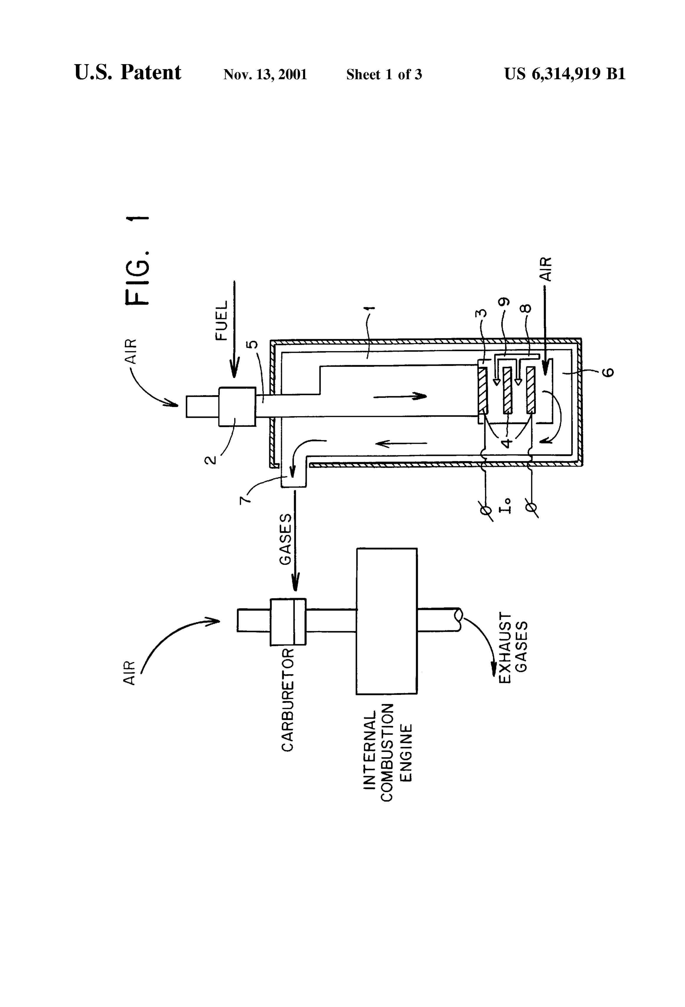
wherein:
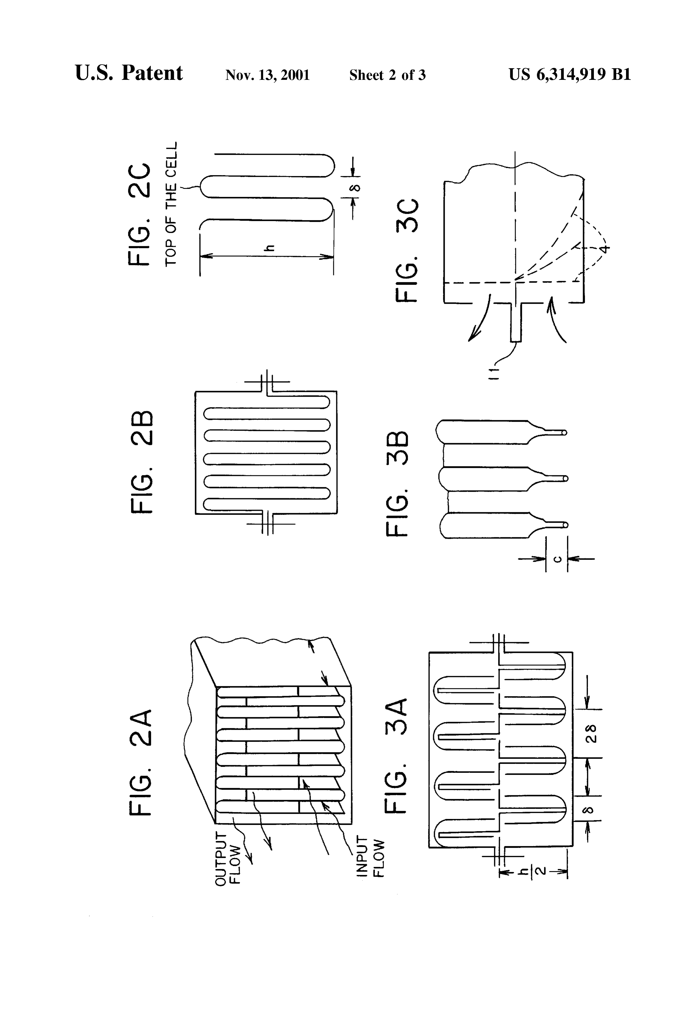
FIG. 1 is a schematic functional diagram of the device for The proposed construction arrangement of the heat carrying out the proposed method; eXchanger makes it possible to do away with devices caus FIG. 2 illustrates variants of a heat-exchanger element: ing the mixture flows to repeatedly turn through 90 degrees. A with a solid-design (welded) shell; When a cell portion is compressed the width of the same B-with a Sectional/nonsectional shell, portion of the adjacent cells increases. Thus, cross-sectional area S of the passage of the outlet (inlet) portion of each cells
C-elements of a cell-duct defined by the corrugated remains unaffected (FIGS. 3, A, B):
partition.
FIG. 3 illustrates the end portions of the heat-exchanger 25
A joined-together (compressed) portions of the walls of where h is the height of a cell, b is the width of a cell.
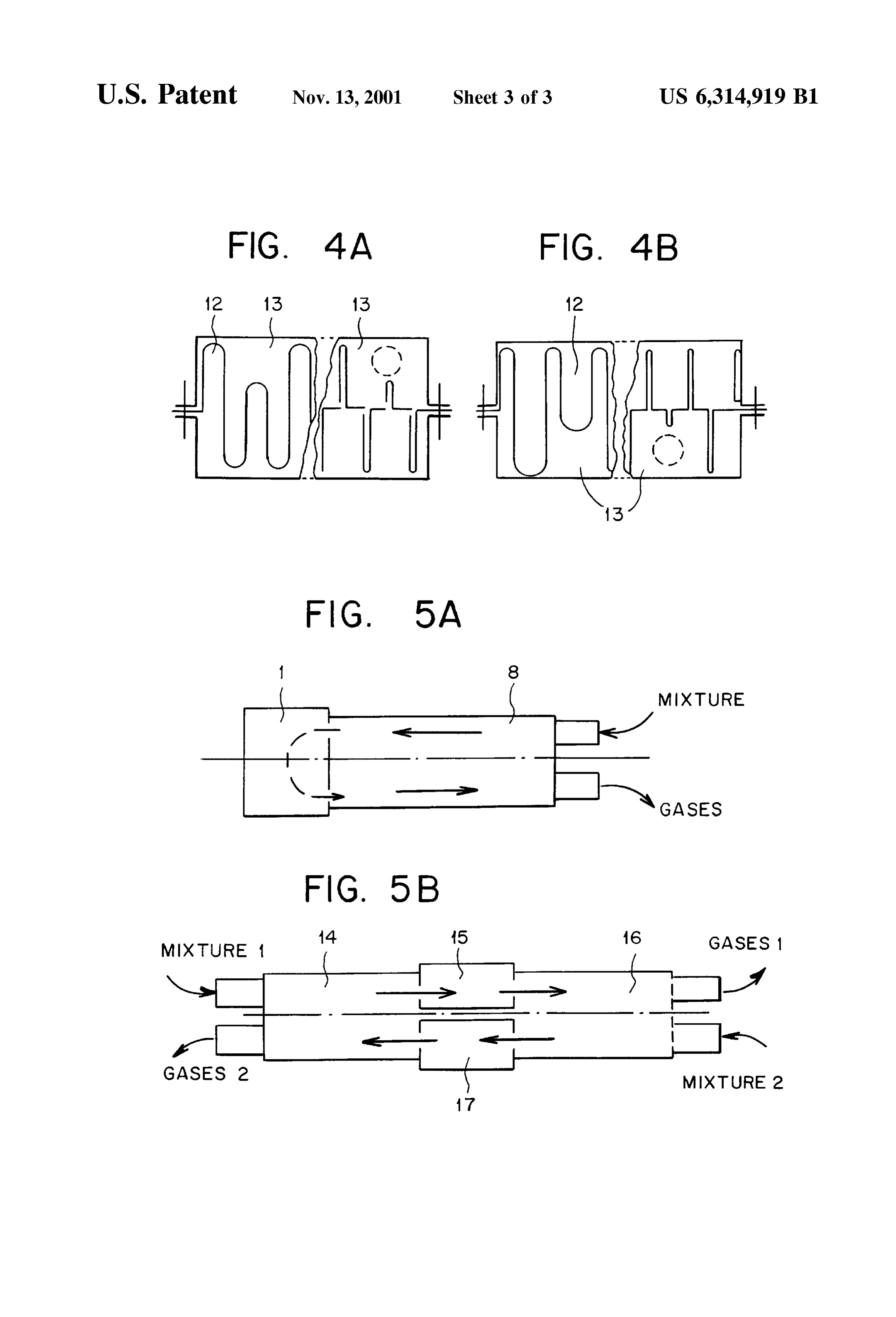
the cells-ducts (front view); Whenever it becomes necessary and depending on the B-same (plan view); construction arrangement of the devices connected to the C-same (side view). heat-exchanger, Such as reactor or promoter chamber, the FIG. 4 illustrates shortened cells-ducts and auxiliary cells grouped according to their inputs/outputs may be Spaces: provided with an additional flow divider 11 (FIG. 3, C). The A-equal-width cells, narrower a cell-duct the better heat eXchange between the B-different-width cells. 35 flows of matter.
FIG. 5 illustrates connection of heat-exchangers to the When the heat-exchanger communicates with a device reactor (promoter) chamber: wherein reactions of liquid fuel decomposition into oil gases A-single (as along the flow) heat-exchanger; occur, the Volume of hot gases at the heat-exchanger outlet B-two Serially connected heat-exchanger elements. is much higher So that the Slit-like ducts for Said gases to
BEST METHOD OF CARRYING OUT THE
40 pass can be wider (FIG. 4, B).
INVENTION Thus, the width of the ducts of both flows is optimized with due account of the aerodynamic drag of each of them.
The device for carrying the proposed method into effect When the cells-ducts are of a small-width the heat comprises a double-loop heat-exchanger 1, a proportioner 2 eXchanger may have an adequately large heat-exchange of the mixture components (fuel and air), a promoter cham 45 Surface area and may operate appropriately, with the lami ber 3 accommodating a promoter 4, an inlet S for fuel-air narity of the flows and their low aerodynamic drag remain mixture communicating the proportioner with the heat ing unaffected.
eXchanger mixture-handling loop, an inlet 6 of the of the Construction arrangement of electric input terminals in heat-exchanger gas-handling loop connected to the outlet of hermetically Sealed chambers accommodating high the promoter chamber, an outlet 7 of the gas-handling loop 50 temperature electric heaters, especially under conditions of through which the resultant gases are admitted to the engine, restricted overall dimensions of the entire device and when and an extra-air piping 8 provided with air nozzles 9 ever it is necessary to provide a “cool” wire electrode for disposed in the promoter chamber. connection to a current Source which is the case with a motor With the proposed device operating, an overrich gasoline vehicle.
air mixture (having an excess air coefficient below 0.45) is 55 To Supply current to the high-temperature chamber, one or prepared in the proportioner 2, which mixture is fed through more heat-exchanger cells along which hot fluid flows have the inlet 5 to the mixture loop of the heat-exchanger 1 and a reduced height 12 (FIG. 4). A space 13 thus defined over to be exposed to thermal action with the aid of the promoter the reduced-height cell accommodates a wire running along 4 in the chamber 3 thereof. Then hot oil gases obtained in the Said Space throughout the heat-exchanger from the “hot” chamber 3 are passed via the inlet 6 of the gas-handling loop 60 chamber towards the inlet of the “cool” fluid (e.g., fuel-air towards the outlet 7, thus giving up their heat to the fuel-air mixture). While running the “cool” flow cools the electric mixture fed by the proportioner 2 along the mixture conductor, thus providing the outlet of the “cool” wire from handling loop to the promoter chamber 3, whereby said hot the heat-exchanger.
gases are cooled. To compensate for the air spent for the Whenever necessary Such spaces can accommodate wire aboveSaid reactions, additional air is fed along the piping 8 65 conductors for the automatic control System monitors and to the promoter chamber, which air is fed to the mixture transducers situated in the high-temperature Zone, as well as being handled via the nozzles 9 downstream of the promoter. pipings feeding necessary additives to the chamber.
Page 9
The proposed heat-exchanger may comprise a single or ignition range, preheating Said overrich flow to produce more heat-exchanging elements enclosed in a common carbon monoxide and hydrogen-containing gases, and mix casing with heat insulation (both casings and heat insulation ing said flow with the other flow of mixture before feeding being not shown in the drawings). said flows of mixture to the engine cylinders, CHARAC To utilize the heat of hot oil gases generated in the reactor TERIZED in that the overrich flow of the fuel-air mixture the latter is connected through its input and output directly containing 10 to 100% of the fuel consumed by the engine to the respective heat-exchanger flow passages. The flow of is Subjected to Single- or multi-stage thermal action by a the preheated fuel-air mixture running from the heat promoter and the air spent for reactions is compensated for eXchanger to the reactor is therein turned through 180 either partially or completely.
degrees to pass throughout the heat-exchanger in the reverse 2. The method of claim 1, CHARACTERIZED in that the direction (FIG. 5, A).
Enhanced aerodynamic characteristics are attained when mixtureairdownstream spent is compensated for by being fed into the flow of of the promoter.
using cocurrent reactors or promoter chambers. In this case 3. The method of claim 1, CHARACTERIZED in that the it is practicable tandem-connection of two heat-exchanging elements or two heat-exchangers for, e.g., a multicylinder 15 flow of overrich fuel-air mixture is preheated by the heat of internal combustion engines (FIG. 5, B). With such a con the resultant hot oil gases, thereby reducing the temperature Struction arrangement the flow of mixture being preheated of Said gases before feeding them to the engine. passes through a first heat-exchanging element 14, then 4. A device for preparing fuel-air mixture for internal through a chamber 15 and, in the form of a gaseous mixture, combustion engines, comprising a double-loop heat through a Second Series-connected heat-exchanging element eXchanger having an inlet piping and an outlet piping, a 16 without reversing its motion. A second flow of mixture is mixture-handling loop, a gas-handling loop, a promoter established and handled similarly to the first one but running chamber, and a proportioner of the mixture components, the in an opposite direction. The mixture of the first flow is inlet of the mixture-handling loop being connected to the heated, upstream of the promoter, by the hot gases of the proportioner of the mixture components and to the promoter second flow of mixture emerging from a chamber 17, while 25 chamber, CHARACTERIZED in that the inlet and outlet the mixture of the second flow is heated by the hot gases of pipings of the gas-handling loop are connected to the the first flow of mixture emerging from the chamber 15. promoter chamber and the inlet duct of the engine for The loss of head of the running flows can be reduced fuel-air mixture, and the promoter chamber accommodates when using fuel injection devices for preparing an initial additional air feeding nozzles.
(starting) fuel-air mixture. Such devices can be installed promoter5. The device of claim 4, CHARACTERIZED in that the immediately on the inlet heat-exchanger Section. is of the multistage design and appears as Succes What is claimed is: Sively arranged Sections, and the air nozzles are provided 1. A method for preparing fuel-air mixture for internal past each of Said Sections.
combustion engines, consisting in establishing two flows of the fuel-air mixture of which one gets overrich below the
Provenance
- Collection
- Patents citing this work
- Pages
- 9
- Method
- pdftotext (the PDF's own text layer) + pdftoppm 300dpi page scans
- Patent office record
- patents.google.com →
- Source
- Google Patents citing-documents table
- Assignee
- Alexandr Vasillevich Pugachev
- Inventors
- Alexandr Vasillevich Pugachev
- Published
- 2001-11-13
- Transcribed from
- patentimages.storage.googleapis.com →