patent · US4019476
Vaporizer apparatus
26 April 1977
Page 1 — bibliographic record
United States Patent to 11, 4,019,476 Ackley 45 Apr. 26, 1977 54 WAPORIZER APPARATUS FOREIGN PATENTS OR APPLICATIONS 76 Inventor: Donald M. Ackley, 11 15 17th St., 639,309 6/1928 France ............................... 123/14 Hermosa Beach, Calif. 90254
Primary Examiner-C. J. Husar (22 Filed: Mar. 31, 1975 Assistant Examiner-ra S. Lazarus Attorney, Agent, or Firm-William W. Haefliger (21) Appl. No. 563,693 57 ABSTRACT (52) U.S. Cl. ........................ 123/119 DB; 123/141; Apparatus to enhance vaporization of liquid particles 261/78 R; 261/47; 48/180 R entrained in a gaseous carrier comprises:
(51 int. C.’........................................ F02M 23/02 a. means including a chamber defining at least two 58 Field of Search .................... 123/141, 119 DB; flow paths for said carrier and particles, the carrier 48/180 R; 261/78 R, 47, 108, DIG. 1 and particles in each path defining a flow stream, 56) References Cited b. said means including surfaces directing said
UNITED STATES PATENTS
streams alternately to merge with mutual impinge ment and to separate, at different locations there 1,761,692 6f 1930 Stepp ...................... 12311 19 DB X along.
2,100,466 1 1/1937 Bashford et al. ............ 12311 19 DB The apparatus has particular utility with a carburetor 2,153,350 4f 1939 Stimac .... 12311 19 DB for an internal combustion engine. 2,588,474 31 1952 Bellios ........................... 1231.41 X 2,661,269 12/1953 Briggs ............................ 123/141 X 2,977,205 3/1961 Austin ........................... 123/141 X 13 Claims, 6 Drawing Figures
Sé SSGANAS
SSAS
ESSES
ZZZZZZZZZZZZZZZZZZZZZZZZZZZZZZZZYZZZIC
SNCSielefies Sisielizei is:
2 R str N Eas N V
iSSNs. S&ce 2-4est N 28 iXNE-S-NEE-ANN OFCC -
Page 2
Drawing sheet — no readable text.
Page 3
Drawing sheet — no readable text.
Page 4
Drawing sheet — no readable text.
Page 5
means such as gears. Each of these two stages of multi
WAPOREZER APPARATUS ple air-injectors can be adjusted independently in both
BACKGROUND OF THE INVENTION
the low and high volume positions, which establishes proportional variations at all positions between the
This invention relates generally to vaporizers, and 5 high and low volumn settings. The change does not more particularly concerns apparatus for enhancing have to be linear but will be determined by the require the ments of the type of engine and its normal loads. In vaporization of liquid particles entrained in a gase addition,
OS Cae. an air passage conduit conducts air from the There is a need in many fields for economizing in the area immediately beneath the control butterfly valve, usage of liquids dispersed in gaseous carriers. En O on the high side of the butterfly, to control mixture hanced economy can be achieved if the extent of va valves, as will be described.
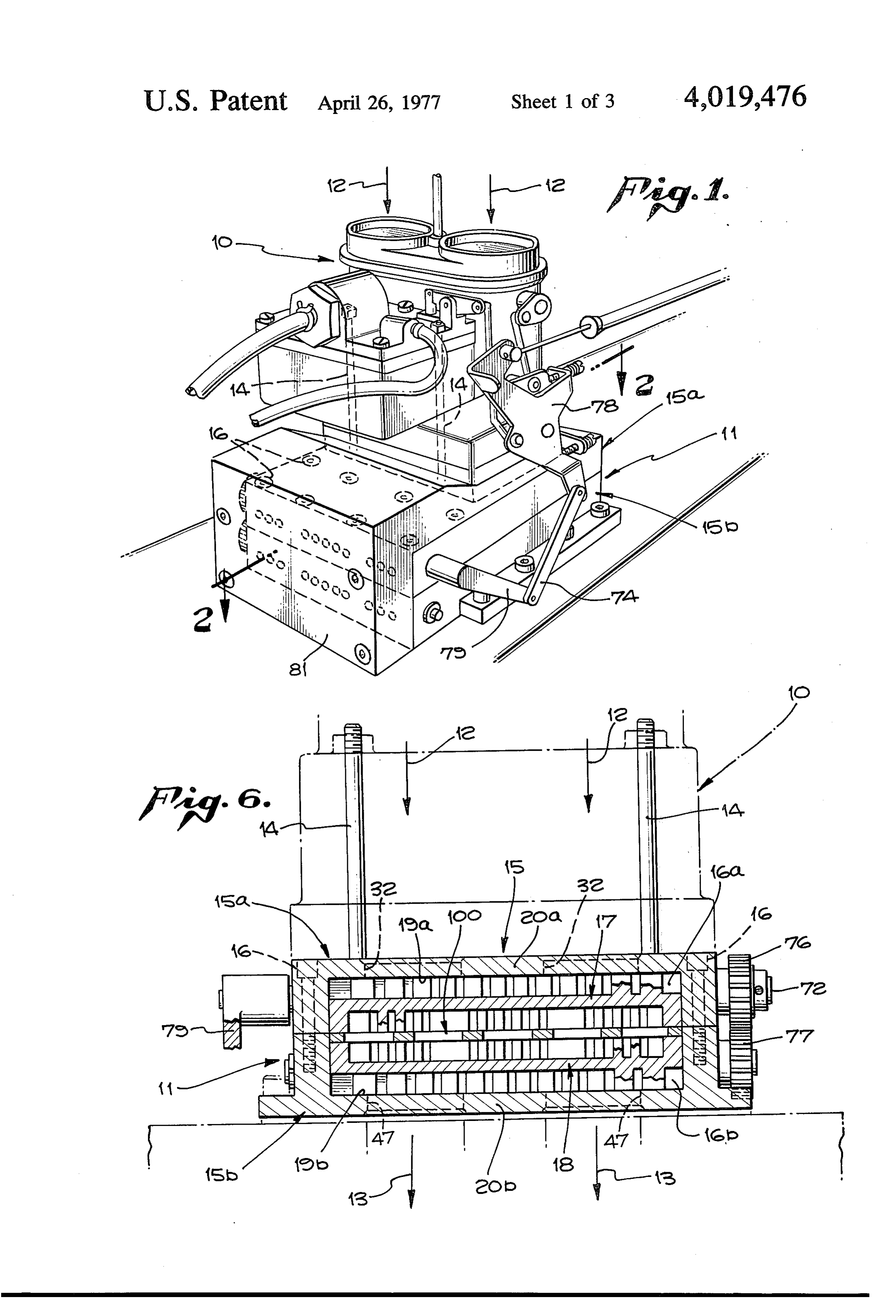
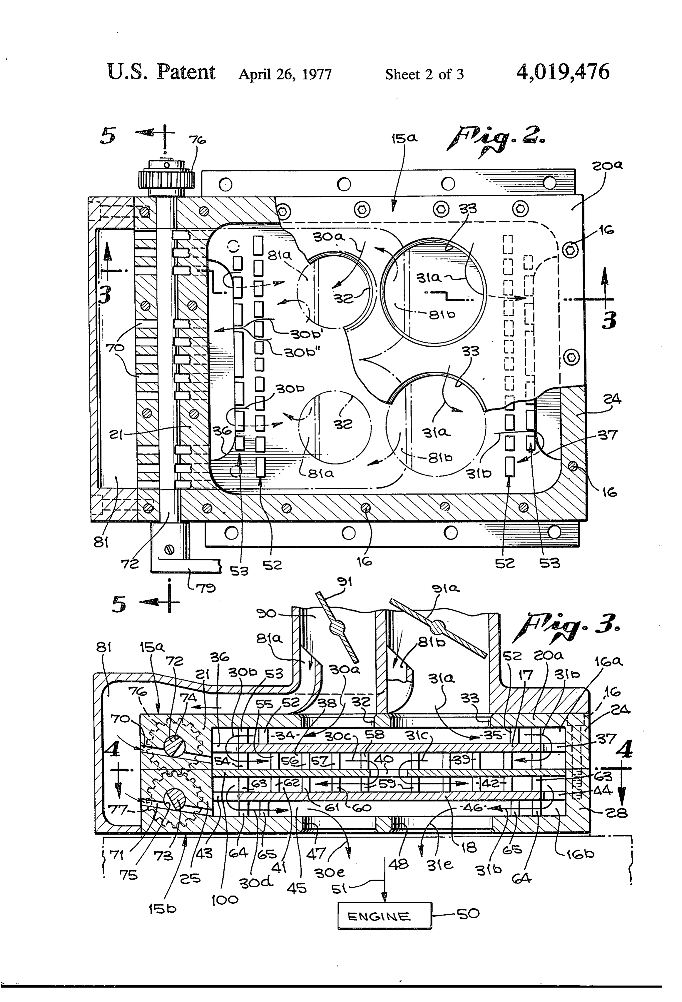
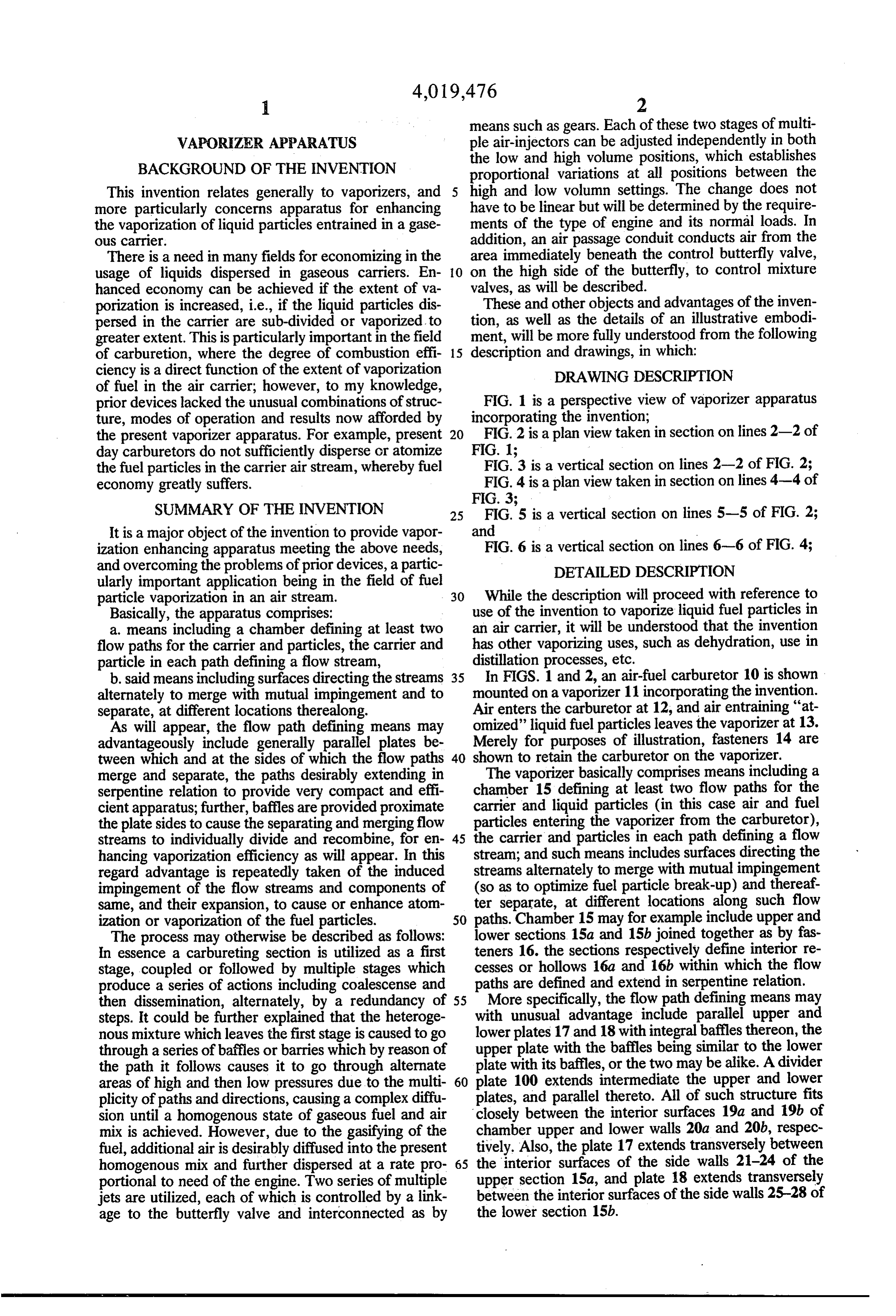
porization is increased, i.e., if the liquid particles dis These and other objects and advantages of the inven persed in the carrier are sub-divided or vaporized to tion, as well as the details of an illustrative embodi greater extent. This is particularly important in the field ment, will be more fully understood from the following of carburetion, where the degree of combustion effi 15 description and drawings, in which: ciency is a direct function of the extent of vaporization DRAWING DESCRIPTION of fuel in the air carrier; however, to my knowledge, prior devices lacked the unusual combinations of struc FIG. 1 is a perspective view of vaporizer apparatus ture, modes of operation and results now afforded by incorporating the invention;
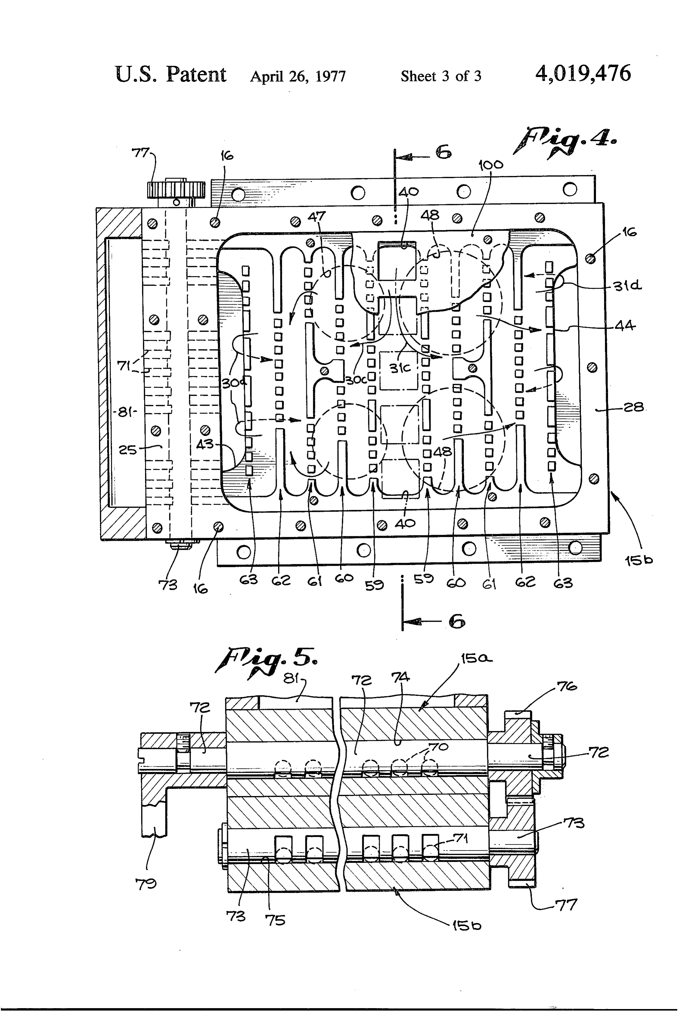
the present vaporizer apparatus. For example, present 20 FIG. 2 is a plan view taken in section on lines 2-2 of day carburetors do not sufficiently disperse or atomize FIG. 1 the fuel particles in the carrier air stream, whereby fuel FiG3 is a vertical section on lines 2-2 of FIG. 2; economy greatly suffers. FIG. 4 is a plan view taken in section on lines 4-4 of FIG. 3
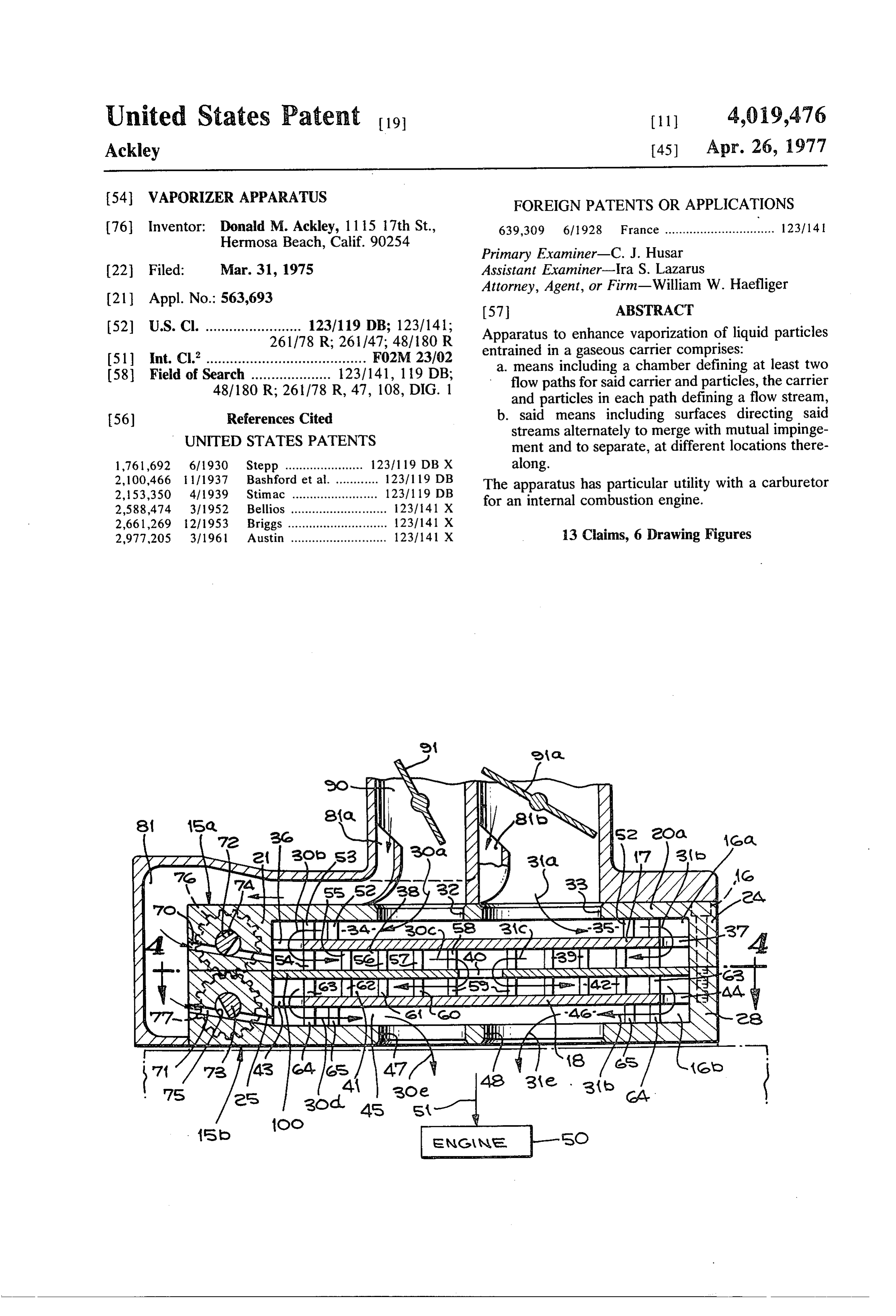
SUMMARY OF THE INVENTION 25 FiG's is a vertical section on lines 5-5 of FIG. 2; It is a major object of the invention to provide vapor and ization enhancing apparatus meeting the above needs, FIG. 6 is a vertical section on lines 6-6 of FIG. 4; and overcoming the problems of prior devices, a partic DETAILED DESCRIPTION ularly important application being in the field of fuel particle vaporization in an air stream. 30 While the description will proceed with reference to Basically, the apparatus comprises: use of the invention to vaporize liquid fuel particles in a means including a chamber defining at least two an air carrier, it will be understood that the invention flow paths for the carrier and particles, the carrier and has other vaporizing uses, such as dehydration, use in particle in each path defining a flow stream, distillation processes, etc. b. said means including surfaces directing the streams 35 In FIGS. 1 and 2, an air-fuel carburetor 10 is shown alternately to merge with mutual impingement and to mounted on a vaporizer 11 incorporating the invention. separate, at different locations therealong. Air enters the carburetor at 12, and air entraining "at As will appear, the flow path defining means may omized' liquid fuel particles leaves the vaporizer at 13. advantageously include generally parallel plates be Merely for purposes of illustration, fasteners 14 are tween which and at the sides of which the flow paths 40 shown to retain the carburetor on the vaporizer. The vaporizer basically comprises means including a merge and separate, the paths desirably extending in serpentine relation to provide very compact and effi chamber 15 defining at least two flow paths for the cient apparatus; further, baffles are provided proximate carrier and liquid particles (in this case air and fuel the plate sides to cause the separating and merging flow particles entering the vaporizer from the carburetor), streams to individually divide and recombine, for en 45 the carrier and particles in each path defining a flow hancing vaporization efficiency as will appear. In this stream; and such means includes surfaces directing the regard advantage is repeatedly taken of the induced streams alternately to merge with mutual impingement impingement of the flow streams and components of (so as to optimize fuel particle break-up) and thereaf same, and their expansion, to cause or enhance atom ter separate, at different locations along such flow ization or vaporization of the fuel particles. 50 paths. Chamber 15 may for example include upper and The process may otherwise be described as follows: lower sections 15a and 15b joined together as by fas In essence a carbureting section is utilized as a first teners 16. the sections respectively define interior re stage, coupled or followed by multiple stages which cesses or hollows 16a and 16b within which the flow produce a series of actions including coalescense and paths are defined and extend in serpentine relation. then dissemination, alternately, by a redundancy of 55 More specifically, the flow path defining means may steps. It could be further explained that the heteroge with unusual advantage include parallel upper and nous mixture which leaves the first stage is caused to go lower plates 17 and 18 with integral baffles thereon, the through a series of baffles or barries which by reason of upper plate with the baffles being similar to the lower the path it follows causes it to go through alternate plate with its baffles, or the two may be alike. A divider areas of high and then low pressures due to the multi 60 plate 100 extends intermediate the upper and lower plicity of paths and directions, causing a complex diffu plates, and parallel thereto. All of such structure fits sion until a homogenous state of gaseous fuel and air closely between the interior surfaces 19a and 19b of mix is achieved. However, due to the gasifying of the chamber upper and lower walls 20a and 20b, respec fuel, additional air is desirably diffused into the present tively. Also, the plate 17 extends transversely between homogenous mix and further dispersed at a rate pro 65 the interior surfaces of the side walls 21-24 of the portional to need of the engine. Two series of multiple upper section 15a, and plate 18 extends transversely jets are utilized, each of which is controlled by a link between the interior surfaces of the side walls 25-28 of age to the butterfly valve and interconnected as by the lower section 15b.
Page 6
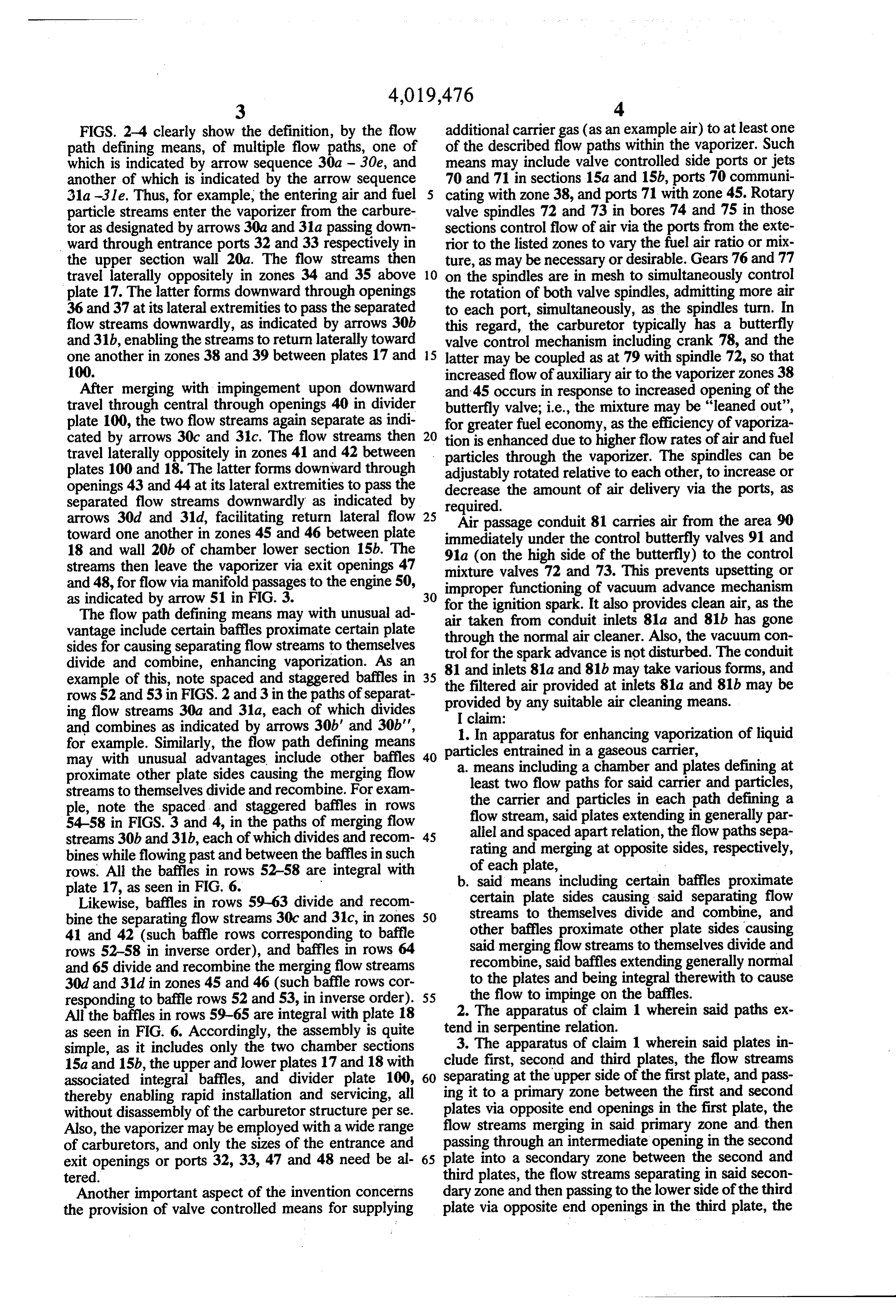
FIGS. 2-4 clearly show the definition, by the flow additional carrier gas (as an example air) to at least one path defining means, of multiple flow paths, one of of the described flow paths within the vaporizer. Such which is indicated by arrow sequence 30a - 30e, and means may include valve controlled side ports or jets another of which is indicated by the arrow sequence 70 and 71 in sections 15a and 15b, ports 70 communi 31a -3 le. Thus, for example, the entering air and fuel cating with zone 38, and ports 71 with zone 45. Rotary particle streams enter the vaporizer from the carbure valve spindles 72 and 73 in bores 74 and 75 in those tor as designated by arrows 30a and 31a passing down sections control flow of air via the ports from the exte ward through entrance ports 32 and 33 respectively in rior to the listed zones to vary the fuel air ratio or mix the upper section wall 20a. The flow streams then ture, as may be necessary or desirable. Gears 76 and 77 travel laterally oppositely in zones 34 and 35 above 10 on the spindles are in mesh to simultaneously control plate 17. The latter forms downward through openings the rotation of both valve spindles, admitting more air 36 and 37 at its lateral extremities to pass the separated to each port, simultaneously, as the spindles turn. In flow streams downwardly, as indicated by arrows 30b this regard, the carburetor typically has a butterfly and 31b, enabling the streams to return laterally toward valve control mechanism including crank 78, and the one another in zones 38 and 39 between plates 17 and 15 latter may be coupled as at 79 with spindle 72, so that 100. increased flow of auxiliary air to the vaporizer zones 38 After merging with impingement upon downward and 45 occurs in response to increased opening of the travel through central through openings 40 in divider butterfly valve; i.e., the mixture may be "leaned out', plate 100, the two flow streams again separate as indi for greater fuel economy, as the efficiency of vaporiza cated by arrows 30c and 31c. The flow streams then 20 tion is enhanced due to higher flow rates of air and fuel travel laterally oppositely in zones 41 and 42 between particles through the vaporizer. The spindles can be plates 100 and 18. The latter forms downward through adjustably rotated relative to each other, to increase or openings 43 and 44 at its lateral extremities to pass the decrease the amount of air delivery via the ports, as separated flow streams downwardly as indicated by required.
arrows 30d and 31d, facilitating return lateral flow 25 Air passage conduit 81 carries air from the area 90 toward one another in zones 45 and 46 between plate immediately under the control butterfly valves 91 and 18 and wall 20b of chamber lower section 15b. The 91a (on the high side of the butterfly) to the control streams then leave the vaporizer via exit openings 47 mixture and 48, for flow via manifold passages to the engine 50, impropervalves 72 and 73. This prevents upsetting or functioning of vacuum advance mechanism
The flow path defining means may with unusual ad air taken from conduitIt inlets for the ignition spark. also provides clean air, as the vantage include certain baffles proximate certain plate through the normal air cleaner.81a and 81b has gone Also, the vacuum con sides for causing separating flow streams to themselves trol for the spark advance is not disturbed. divide and combine, enhancing vaporization. As an 81 and inlets 81a and 81b may take variousThe conduit example of this, note spaced and staggered baffles in 35 the filtered air provided at inlets 81a and 81b mayand forms,
rows 52 and 53 in FIGS. 2 and 3 in the paths of separat provided by any suitable air cleaning means. ing flow streams 30a and 31a, each of which divides I claim:
and combines as indicated by arrows 30b' and 30b', 1. In apparatus for enhancing vaporization of liquid for example. Similarly, the flow path defining means particles entrained in a gaseous carrier, may with unusual advantages include other baffles 40 a means including a chamber and plates defining at proximate other plate sides causing the merging flow least two flow paths for said carrier and particles, streams to themselves divide and recombine. For exam ple, note the spaced and staggered baffles in rows the carrier and particles in each path defining a 54-58 in FIGS. 3 and 4, in the paths of merging flow flow stream, said plates extending in generally par streams 30b and 31b, each of which divides and recom 45 allel and spaced apart relation, the flow paths sepa bines while flowing past and between the baffles in such rating and merging at opposite sides, respectively, rows. All the baffles in rows 52-58 are integral with of each plate, plate 17, as seen in FIG. 6. b. said means including certain baffles proximate Likewise, baffles in rows 59-63 divide and recom certain plate sides causing said separating flow bine the separating flow streams 30c and 31c, in zones 50 streams to themselves divide and combine, and other baffles proximate other plate sides causing 41 and 42 (such baffle rows corresponding to baffle rows 52-58 in inverse order), and baffles in rows 64 said merging flow streams to themselves divide and and 65 divide and recombine the merging flow streams recombine, said baffles extending generally normal 30d and 31d in zones 45 and 46 (such baffle rows cor to the plates and being integral therewith to cause responding to baffle rows 52 and 53, in inverse order). 55 2.the flow to impinge on the baffles. The apparatus of claim 1 wherein said paths ex
All the baffles in rows 59-65 are integral with plate 18 as seen in FIG. 6. Accordingly, the assembly is quite tend in serpentine relation.
simple, as it includes only the two chamber sections 3. The apparatus of claim 1 wherein said plates in 15a and 15b, the upper and lower plates 17 and 18 with clude first, second and third plates, the flow streams associated integral baffles, and divider plate 100, 60 separating at the upper side of the first plate, and pass thereby enabling rapid installation and servicing, all ing it to a primary zone between the first and second without disassembly of the carburetor structure perse. plates via opposite end openings in the first plate, the Also, the vaporizer may be employed with a wide range flow streams merging in said primary zone and then of carburetors, and only the sizes of the entrance and passing through an intermediate opening in the second exit openings or ports 32, 33, 47 and 48 need be al 65 plate into a secondary zone between the second and tered. third plates, the flow streams separating in said secon Another important aspect of the invention concerns dary zone and then passing to the lower side of the third the provision of valve controlled means for supplying plate via opposite end openings in the third plate, the
Page 7
flow streams then merging at said lower side of the of said flow paths downstream of a flow stream en third plate. trance defined by said chamber. 4. The apparatus of claim 3 wherein said apparatus has9.atThe apparatus of claim 3 wherein said chamber includes upper and lower chamber sections enclosing valve meansone least inlet for said flow stream, and including for supplying additional gaseous carrier to said plates, there being two inlet openings in the upper at least one of said flow path downstream of said en section located to pass the carrier in two flow streams, trance and proximate an edge portion of at least one of one stream to the left and the other stream to the right said plates.
at the upper side of the first plate, there being a carbu 10. The apparatus of claim 1 wherein said apparatus retor having two barrels respectively in alignment with 10 comprises a dehydrator.
said two inlet openings and in direct communication comprises distillationofstructure.
11. The apparatus claim 1 wherein said apparatus therewith. 12. The apparatus of claim 6 including a carburetor 5. The apparatus of claim 3 wherein said two flow mounted on the vaporizer apparatus, the carburetor paths are generally symmetrical adjacent plate sur 15 having butterfly valve controlling mechanism, said faces. mechanism coupled with said means to control supply 6. The apparatus of claim 3 including valve con of additional air to at least one of said flow paths to trolled means for supplying additional carrier to at least increase said supply of additional air in response to increased opening of said butterfly valve.
one of said flow path. 13. The apparatus of claim 12 wherein said valve 7. The apparatus of claim 1 including means supply 20 controlled means includes an air valve proximate a side ing said flow to said apparatus and in the form of liquid of said chamber, and a conduit communicating directly fuel particles entrained in air carrier. between the downstream side of the carburetor butter 8. The apparatus of claim 7 including valve con fly valve and said airck valve. k -k sk. k. trolled means for supplying additional air to at least one 25
Provenance
- Collection
- Cited prior art
- Original PDF
- patentimages.storage.googleapis.com →
- Filed
- 1975-03-31
- Pages
- 7
- Method
- pdftotext (the PDF's own text layer) + pdftoppm 300dpi page scans
- Source
- Google Patents bibliographic record
- Granted
- 1977-04-26
- Inventors
- Donald M. Ackley
- Transcribed from
- patentimages.storage.googleapis.com →