patent · US4303051
Fuel economizer
1 December 1981
Page 1
United States Patent (19) 11) 4,303,051 Weishaar 45) Dec. 1, 1981 54 FUEL ECONOMIZER 3,828,736.8/1974 Koch ....................................... 123/3 3,855,980 12/1974 Weisz. 123/122 E 75) Inventor: Rainer E. Weishaar, Mt. Clemens, 4,003,356 1/1977 Naylor. - a - a -- - --- 123/122 E Mich. 4,008,692 2/1977 Shinohara ............................... 123/3 (73) Assignee: Michigan Motor Corporation, Mt. 4,044,742 8/1977 Linder ................................. 261/145 4,083,340, 4/1978 Furr ................................ 123/122 E
Clemens, Mich.
FOREIGN PATENT DOCUMENTS
579942 7/1959 Canada ................................ 219/306
51 Int, C. ............................................. FO2M 31/00 Primary Examiner-Ronald H. Lazarus 52 U.S.C. ......................................... 123/557; 123/3 Attorney, Agent, or Firm-Whittemore, Hulbert & (58) Field of Search ............... 123/122 E, 3, 557, 558, Belknap 123/537, 538,549; 219/206, 207, 306, 307; 57 ABSTRACT
An engine fuel economizer comprising an electric fuel 56) References Cited heating device interposed between the fuel pump and
350,769 10/1886 Ragot............................... 123/122 E buretor, a catalytic vapor condenser and filter inter 745,199. 4/1978 Youngquist ......................... 219/306 posed between the heating device and carburetor, and a 1,065,580 6/1913 Beucus .... ... 123/122 F relief valve interposed between the heating device and 1,532,89 4/1925 Lamont ............................... 219/306 vapor condenser and connected to the fuel line between 2,247,181 6/1941 Berhonda ... ... 123/33 the fuel tank and fuel pump.
2,686,863 8/1954 Chandler ......... 4 we we 89/306
3,717,129 2/1973 Fox .......... w ... 123/3 19 Claims, 5 Drawing Figures
Page 2
Drawing sheet — no readable text.
Page 3
Drawing sheet — no readable text.
Page 4
is to prevent passage of any metal particles from the
FUEL ECONOMIZER condensing chamber to the carburetor.
To prevent development of a pressure of the fuel as - SUMMARY OF THE INVENTION supplied to the vapor condenser, a pressure relief valve The present invention was developed for incorpora is connected between the heater and condenser, which tion into the fuel system of an automotive vehicle using is set to maintain pressure below a predetermined value, a gasoline powered internal combustion engine. Its util as might occur from heating and/or partial vaporization ity is not so limited, and it may be employed in the fuel of the fuel as a consequence of being heated because of supply system of any gasoline powered internal com O a check valve between the fuel pump and heater. The bustion engine. relief valve is connected to the fuel line intermediate the The fuel economizer has been rigorously tested in fuel tank and fuel pump.
automobiles, and fuel savings up to 30% have been ciency The very significant improvement in engine effi obtained. and fuel economy is evidently attributable to a The usual automotive vehicle using a gasoline pow 15. more efficient burning and utilization of the fuel in the ered internal combustion engine comprises a fuel tank, a engine. No completely satisfactory theoretical explana fuel pump, and a carburetor. The carburetor is provided tions for the improved results have been found, but the with a well for receiving gasoline from the fuel pump, improved results have been established by rigorous and a float controlled valve maintains the gasoline at a comparative tests before and after installation of the : constant level in the well. The usual carburetor includes 20 economizer in many different types of automobiles and a venturi through which air for combustion is drawn at under widely varying conditions.
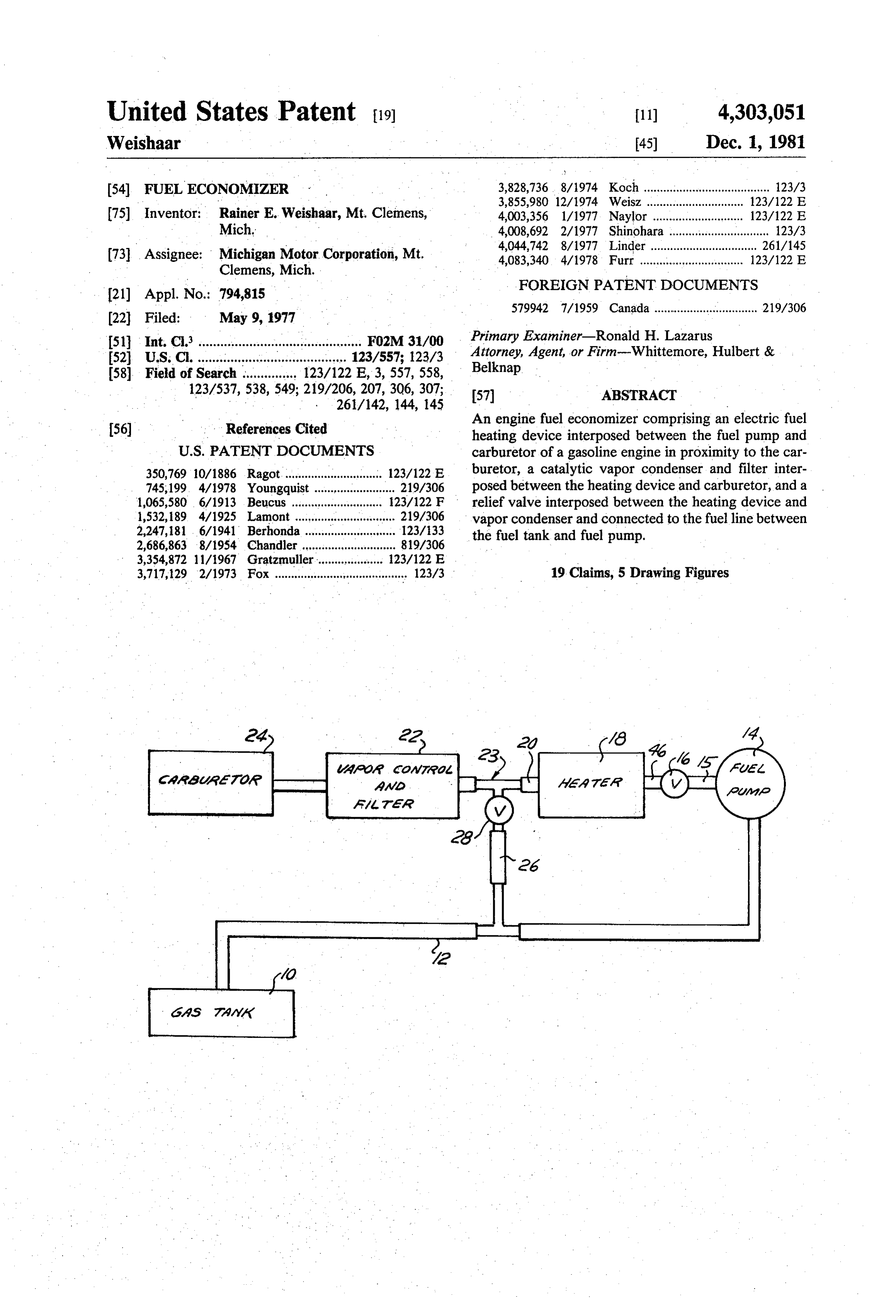
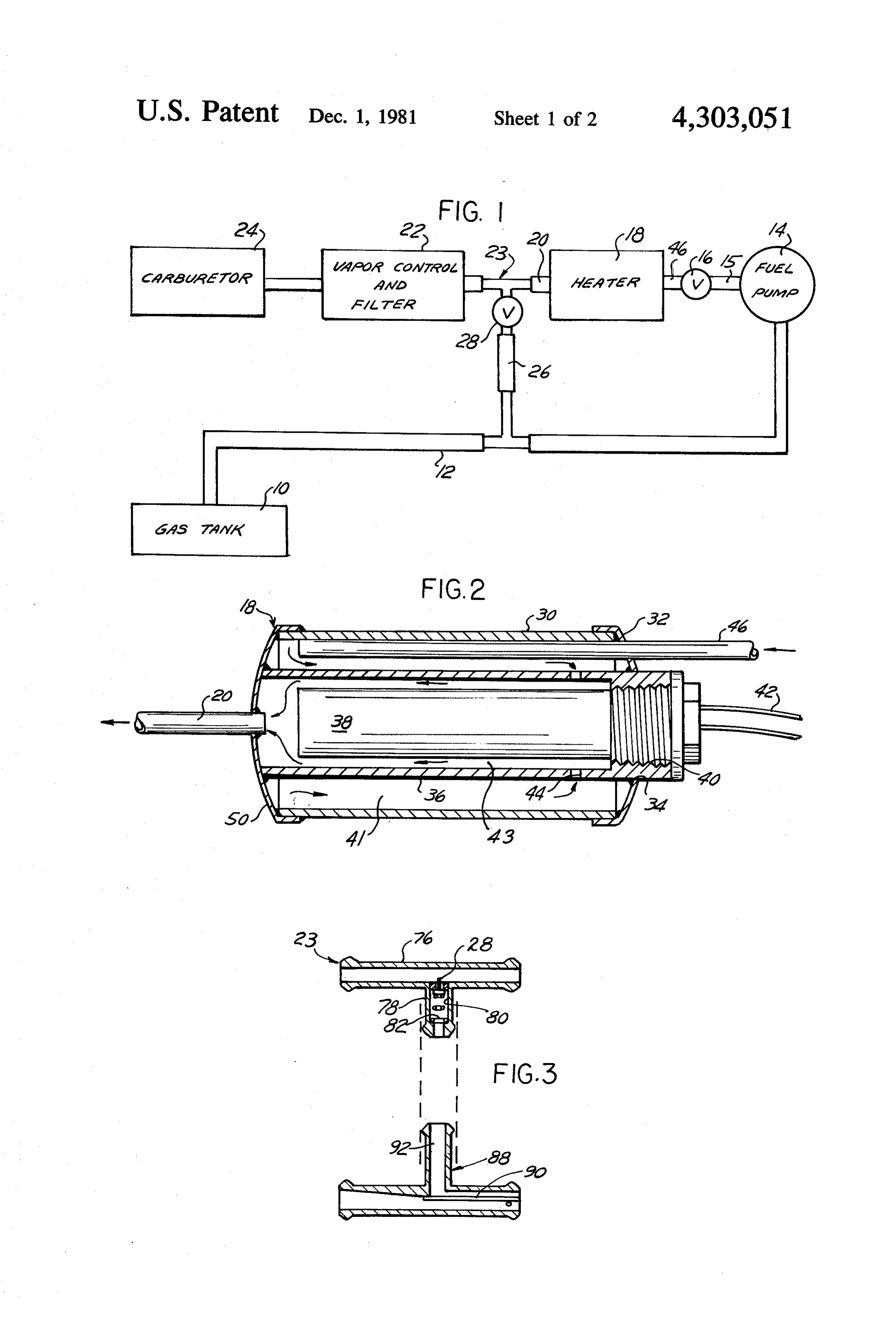
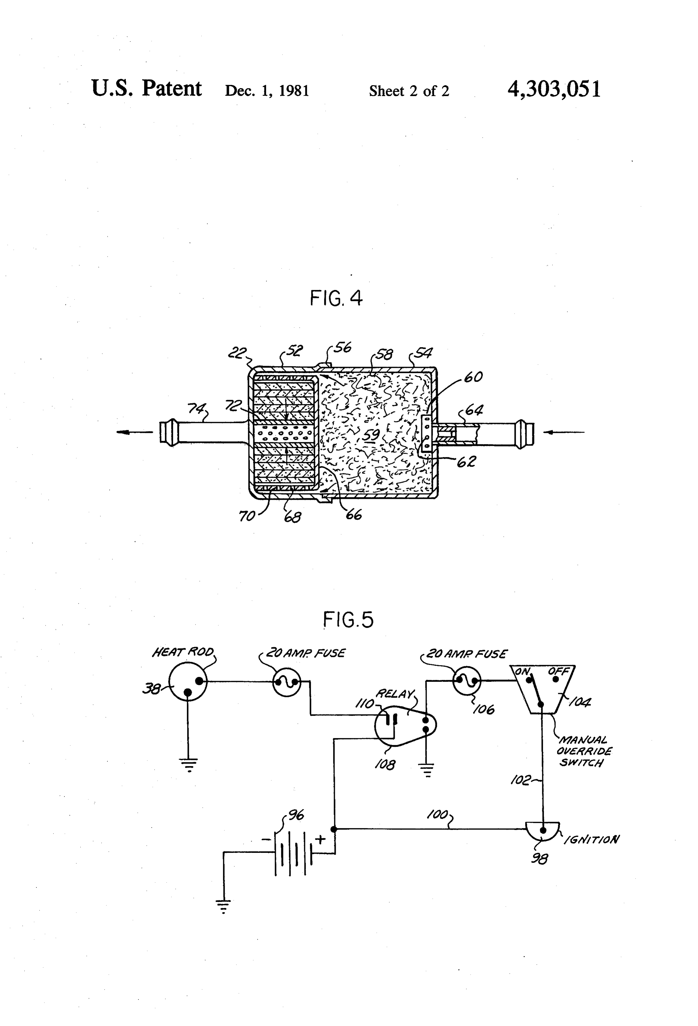
substantial velocity, thus producing in the venturia pressure substantially less than atmospheric. This re BRIEF DESCRIPTION OF THE DRAWINGS duced pressure includes a flow of fuel from the well of FIG. 1 is a diagrammatic view of the fuel supply the carburetor, and as the gasoline in liquid phase 25 system from the fuel tank to the carburetor of an inter emerges from jets or nozzles within the venturi, it is nal combustion engine.
atomized or vaporized, or both, and mixed with the FIG. 2 is an enlarged sectional view of the heater combustion air flowing through the venturi. seen in FIG. I.
. This mixture of air and fuel is delivered to a manifold FIG. 3 is an elevational view, partly in section, of the and from the manifold is drawn into the engine cylin 30. pressure relief connection seen in FIG. 1. ders during the suction strokes of the pistons therein. FIG. 4 is an enlarged sectional view of the vapor The fuel-air mixture is compressed in each cylinder condenser-filter seen in FIG. 1, and during the compression stroke of the piston, and is then FIG. 5 is a simplified wiring diagram of the electrical ignited, either by a spark in the conventional engine, or system.
by compression with or without supplementary heating 35 DETAILED DESCRIPTION means, in a diesel engine. Ideally, combustion of the fuel-air mixture, which is initiated at the sparkplug gap, Referring now to the drawings, the complete system progresses rapidly and is fully complete at the end of the for supplying fuel from the fuel tank to the engine car power, stroke of the cylinder. Too rapid burning or buretor is shown diagrammatically. Fuel is pumped detonation is wasteful and causes knocking. Too slow from the fuel tank 10 through fuel line 12 by a fuel pump burning results in some fuel failing to burn and being 14. The fuel delivered by pump 14 flows through a fuel discharged in the exhaust. It is recognized that in the line 15 and check valve 16 to the heater 18 where it is usual 4-cycle gasoline engine a very substantial percent heated as required to the desired temperature. The fuel age of fuel is wasted, and a relatively small percentage then flows through fuel line 20 to the vapor condenser of the total energy available in the fuel is converted into 45 filter unit 22, which, as will later appear, includes a usable energy by the engine. built-in check valve. From the unit 22 the fuel, in en The usual fuel pump in automobile engines is a dia tirely liquid phase, flows to the carburetor 24. The car phragm pump, in which the force applied to the dia buretor is entirely conventional, and includes a well for phragm during the pumping stroke, is determined by a receiving liquid gasoline, and a float controlled needle spring so that in theory, the fuel is delivered by the 50 valve for maintaining the fuel at a predetermined level pump at a rate determined by consumption and at a in the well, none of these conventional elements being pressure determined by the spring. Flow to the carbure illustrated.
tor well is controlled by a float controlled needle valve, Intermediate the heater 18 and the vapor condenser as previously described. - filter 22 is a fuel return device 23 including a pressure In accordance with the present invention, the fuel 55 relief valve 28 connected to fuel line 12 through line 26 economizer comprises a heater having a small chamber to prevent development of undesirably high pressure in connected into the fuel line between the fuel pump and the system from expansion and/or vaporization of fuel. carburetor, and an electric heater in the chamber. The Fuel passing relief valve 28 will return to fuel line 12 capacity of the chamber is small so that the quantity of and will eventually be recirculated by fuel pump 14. fuel in the chamber is quickly brought to the desired 60 The fuel pump 14 and the carburetor 24 are conven temperature. A vapor condenser and filter unit is con tional and are preferably the usual pump and carburetor nected between the heater and carburetor. The vapor provided in the vehicle. The fuel economizer of the condenser comprises a small condensing chamber - present invention is installed by cutting fuel lines 12 and packed with metal wool, or shavings, filaments or pel- . 15 and inserting the heater, vapor condenser-filter, and lets, which functions to ensure that fuel is delivered 65 return device 23 with relief valve 26 therein. Fuel therefrom in liquid phase. The vapor condenser in pumps as presently provided are variable delivery, con cludes an auxiliary chamber downstream from the con stant pressure diaphragm pumps, as is well understood densing chamber which receives a filter whose function in the art.
Page 5
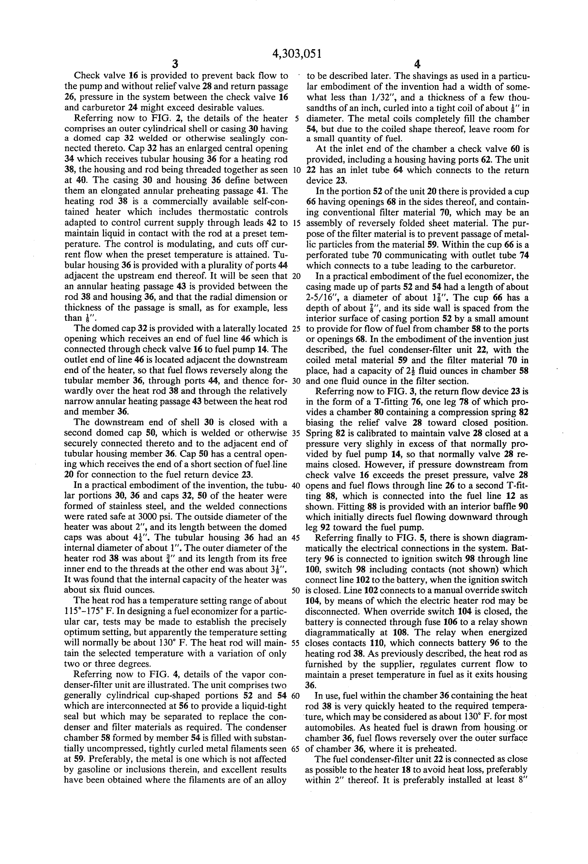
Check valve 16 is provided to prevent back flow to to be described later. The shavings as used in a particu the pump and without relief valve 28 and return passage lar embodiment of the invention had a width of some 26, pressure in the system between the check valve 16 what less than 1/32', and a thickness of a few thou and carburetor 24 might exceed desirable values. Sandths of an inch, curled into a tight coil of about ' in Referring now to FIG, 2, the details of the heater diameter. The metal coils completely fill the chamber comprises an outer cylindrical shell or casing 30 having 54, but due to the coiled shape thereof, leave room for a domed cap 32 welded or otherwise sealingly con a small quantity of fuel.
nected thereto. Cap 32 has an enlarged central opening At the inlet end of the chamber a check valve 60 is 34 which receives tubular housing 36 for a heating rod provided, including a housing having ports 62. The unit 38, the housing and rod being threaded together as seen 10 22 has an inlet tube 64 which connects to the return at 4). The casing 30 and housing 36 define between device 23.
them an elongated annular preheating passage 41. The In the portion 52 of the unit 20 there is provided a cup heating rod 38 is a commercially available self-con 66 having openings 68 in the sides thereof, and contain tained heater which includes thermostatic controls ing conventional filter material 70, which may be an adapted to control current supply through leads 42 to 5 assembly of reversely folded sheet material. The pur maintain liquid in contact with the rod at a preset tem pose of the filter material is to prevent passage of metal perature. The control is modulating, and cuts off cur lic particles from the material 59. Within the cup 66 is a rent flow when the preset temperature is attained. Tu perforated tube 70 communicating with outlet tube 74 bular housing 36 is provided with a plurality of ports 44 which connects to a tube leading to the carburetor. adjacent the upstream end thereof. It will be seen that 20 In a practical embodiment of the fuel economizer, the an annular heating passage 43 is provided between the casing made up of parts 52 and 54 had a length of about rod 38 and housing 36, and that the radial dimension or 2-5/16", a diameter of about 1". The cup 66 has a thickness of the passage is small, as for example, less depth of about ", and its side wall is spaced from the than '. interior surface of casing portion 52 by a small amount The domed cap 32 is provided with a laterally located 25 to provide for flow of fuel from chamber 58 to the ports opening which receives an end of fuel line 46 which is or openings 68. In the embodiment of the invention just connected through check valve 16 to fuel pump 14. The described, the fuel condenser-filter unit 22, with the outlet end of line 46 is located adjacent the downstream coiled metal material 59 and the filter material 70 in end of the heater, so that fuel flows reversely along the place, had a capacity of 2 fluid ounces in chamber 58 tubular member 36, through ports 44, and thence for and one fluid ounce in the filter section. wardly over the heat rod 38 and through the relatively Referring now to FIG. 3, the return flow device 23 is narrow annular heating passage 43 between the heat rod in the form of a T-fitting 76, one leg 78 of which pro and member 36. vides a chamber 80 containing a compression spring 82 The downstream end of shell 30 is closed with a biasing the relief valve 28 toward closed position. second domed cap 50, which is welded or otherwise 35 Spring 82 is calibrated to maintain valve 28 closed at a securely connected thereto and to the adjacent end of pressure very slighly in excess of that normally pro tubular housing member 36. Cap 50 has a central open vided by fuel pump 14, so that normally valve 28 re ing which receives the end of a short section of fuel line mains closed. However, if pressure downstream from 20 for connection to the fuel return device 23. check valve 16 exceeds the preset pressure, valve 28 In a practical embodiment of the invention, the tubu 40 opens and fuel flows through line 26 to a second T-fit lar portions 30, 36 and caps 32, 50 of the heater were ting 88, which is connected into the fuel line 12 as formed of stainless steel, and the welded connections shown. Fitting 88 is provided with an interior baffle 90 were rated safe at 3000 psi. The outside diameter of the which initially directs fuel flowing downward through heater was about 2', and its length between the domed leg 92 toward the fuel pump.
caps was about 43". The tubular housing 36 had an 45 Referring finally to FIG. 5, there is shown diagram internal diameter of about 1'. The outer diameter of the matically the electrical connections in the system. Bat heater rod 38 was about 3" and its length from its free tery 96 is connected to ignition switch 98 through line inner end to the threads at the other end was about 3". 100, switch 98 including contacts (not shown) which It was found that the internal capacity of the heater was connect line 102 to the battery, when the ignition switch about six fluid ounces. 50 is closed. Line 102 connects to a manual override switch The heat rod has a temperature setting range of about 104, by means of which the electric heater rod may be 115-175 F. In designing a fuel economizer for a partic disconnected. When override switch 104 is closed, the ular car, tests may be made to establish the precisely battery is connected through fuse 106 to a relay shown optimum setting, but apparently the temperature setting diagrammatically at 108. The relay when energized will normally be about 130 F. The heat rod will main 55 closes contacts 10, which connects battery 96 to the tain the selected temperature with a variation of only heating rod 38. As previously described, the heat rod as two or three degrees. furnished by the supplier, regulates current flow to Referring now to FIG. 4, details of the vapor con maintain a preset temperature in fuel as it exits housing denser-filter unit are illustrated. The unit comprises two 36.
generally cylindrical cup-shaped portions 52 and 54 60 In use, fuel within the chamber 36 containing the heat which are interconnected at 56 to provide a liquid-tight rod 38 is very quickly heated to the required tempera seal but which may be separated to replace the con ture, which may be considered as about 130 F. for most denser and filter materials as required. The condenser automobiles. As heated fuel is drawn from housing or chamber 58 formed by member 54 is filled with substan chamber 36, fuel flows reversely over the outer surface tially uncompressed, tightly curled metal filaments seen 65 of chamber 36, where it is preheated. at 59. Preferably, the metal is one which is not affected The fuel condenser-filter unit 22 is connected as close by gasoline or inclusions therein, and excellent results as possible to the heater 18 to avoid heat loss, preferably have been obtained where the filaments are of an alloy within 2" thereof. It is preferably installed at least 8"
Page 6
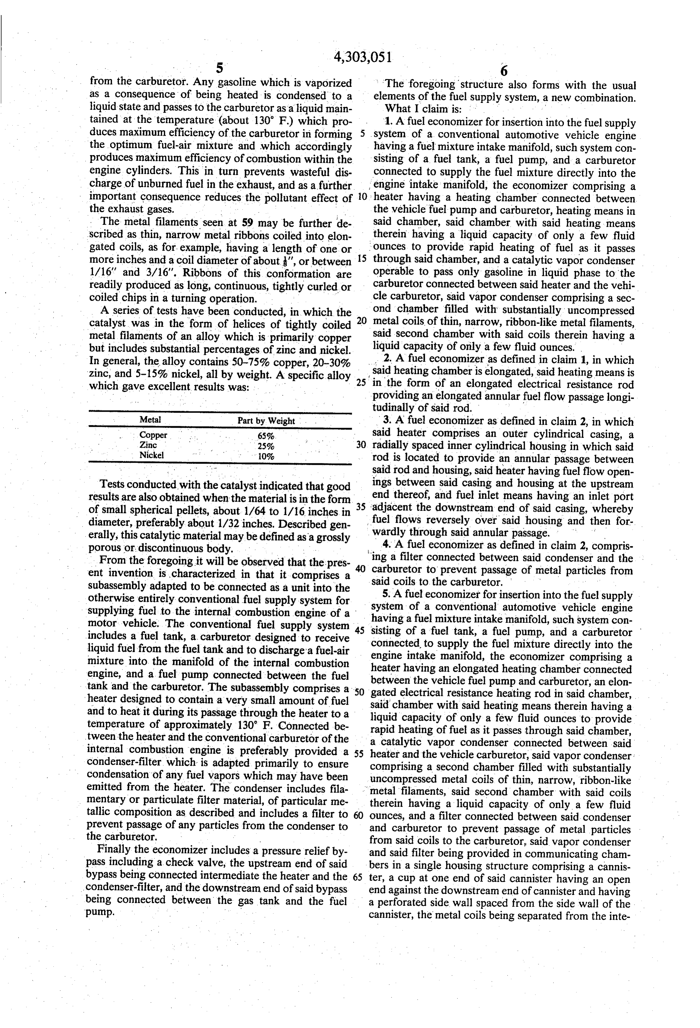
from the carburetor. Any gasoline which is vaporized The foregoing structure also forms with the usual as a consequence of being heated is condensed to a elements of the fuel supply system, a new combination. liquid state and passes to the carburetor as a liquid main What I claim is: - tained at the temperature (about 130' F.) which pro 1. A fuel economizer for insertion into the fuel supply duces maximum efficiency of the carburetor in forming 5 system of a conventional automotive vehicle engine the optimum fuel-air mixture and which accordingly having a fuel mixture intake manifold, such system con produces maximum efficiency of combustion within the sisting of a fuel tank, a fuel pump, and a carburetor engine cylinders. This in turn prevents wasteful dis connected to supply the fuel mixture directly into the charge of unburned fuel in the exhaust, and as a further engine intake manifold, the economizer comprising a important consequence reduces the pollutant effect of 10 heater having a heating chamber connected between the exhaust gases. the vehicle fuel pump and carburetor, heating means in The metal filaments seen at 59 may be further de therein said chamber, said chamber with said heating means having a liquid capacity of only a few fluid scribed as thin, narrow metal ribbons coiled into elon gated coils, as for example, having a length of one or ounces to provide rapid heating of fuel as it passes more inches and a coil diameter of about', or between 15 through said chamber, and a catalytic vapor condenser 1/16' and 3/16". Ribbons of this conformation are operable to pass only gasoline in liquid phase to the readily produced as long, continuous, tightly curled or carburetor connected between said heater and the vehi coiled chips in a turning operation. cle carburetor, said vapor condenser comprising a sec A series of tests have been conducted, in which the 20 ond chamber filled with substantially uncompressed catalyst was in the form of helices of tightly coiled metal coils of thin, narrow, ribbon-like metal filaments, metal filaments of an alloy which is primarily copper said second chamber with said coils therein having a but includes substantial percentages of zinc and nickel. liquid capacity of only a few fluid ounces. In general, the alloy contains 50-75% copper, 20-30% 2. A fuel economizer as defined in claim 1, in which zinc, and 5-15% nickel, all by weight. A specific alloy 25 said heating chamber is elongated, said heating means is which gave excellent results was: in the form of an elongated electrical resistance rod providing an elongated annular fuel flow passage longi tudinally of said rod.
Metal Part by Weight 3. A fuel economizer as defined in claim 2, in which Copper 65% said heater comprises an outer cylindrical casing, a Zinc 25% 30 radially spaced inner cylindrical housing in which said Nickel 10% rod is located to provide an annular passage between said rod and housing, said heater having fuel flow open
Tests conducted with the catalyst indicated that good ings between said casing and housing at the upstream results are also obtained when the material is in the form end thereof, and fuel inlet means having an inlet port of small spherical pellets, about 1/64 to 1/16 inches in 35 adjacent the downstream end of said casing, whereby diameter, preferably about 1/32 inches. Described gen fuel flows reversely over said housing and then for erally, this catalytic material may be defined as a grossly wardly through said annular passage. porous or discontinuous body. 4. A fuel economizer as defined in claim 2, compris From the foregoing it will be observed that the pres 'ing a filter connected between said condenser and the ent invention is characterized in that it comprises a carburetor to prevent passage of metal particles from subassembly adapted to be connected as a unit into the said coils to the carburetor.
otherwise entirely conventional fuel supply system for 5. A fuel economizer for insertion into the fuel supply supplying fuel to the internal combustion engine of a systemhaving a of a conventional automotive vehicle engine fuel mixture intake manifold, such system con motor vehicle. The conventional fuel supply system 45 includes a fuel tank, a carburetor designed to receive sisting of a fuel tank, a fuel pump, and a carburetor connected to supply the fuel mixture directly into the liquid fuel from the fuel tank and to discharge a fuel-air engine intake manifold, the economizer comprising a mixture into the manifold of the internal combustion engine, and a fuel pump connected between the fuel heater having an elongated heating chamber connected tank and the carburetor. The subassembly comprises a 50 between the vehicle fuel pump and carburetor, an elon gated electrical resistance heating rod in said chamber, heater designed to contain a very small amount of fuel said and to heat it during its passage through the heater to a liquidchamber with said heating means therein having a temperature of approximately 130 F. Connected be rapid heating ofoffuelonly capacity
a few fluid ounces to provide it passes through said chamber, tween the heater and the conventional carburetor of the a catalytic vapor condenser internal combustion engine is preferably provided a 55 heater and the vehicle carburetor, connected between said condenser-filter which is adapted primarily to ensure comprising said vapor condenser: a second chamber condensation of any fuel vapors which may have been uncompressed metal coils of thin, narrow, filled with substantially emitted from the heater. The condenser includes fila ribbon-like mentary or particulate filter material, of particular me therein having a liquid capacity of only a said metal filaments, said second chamber with coils few fluid tallic composition as described and includes a filter to 60 ounces, and a filter connected between said condenser prevent passage of any particles from the condenser to and carburetor to prevent passage of metal particles the carburetor. from said coils to the carburetor, said vapor condenser Finally the economizer includes a pressure relief by and said filter being provided in communicating cham pass including a check valve, the upstream end of said bers in a single housing structure comprising a cannis bypass being connected intermediate the heater and the 65 ter, a cup at one end of said cannister having an open condenser-filter, and the downstream end of said bypass end against the downstream end of cannister and having being connected between the gas tank and the fuel a perforated side wall spaced from the side wall of the pump. cannister, the metal coils being separated from the inte
Page 7
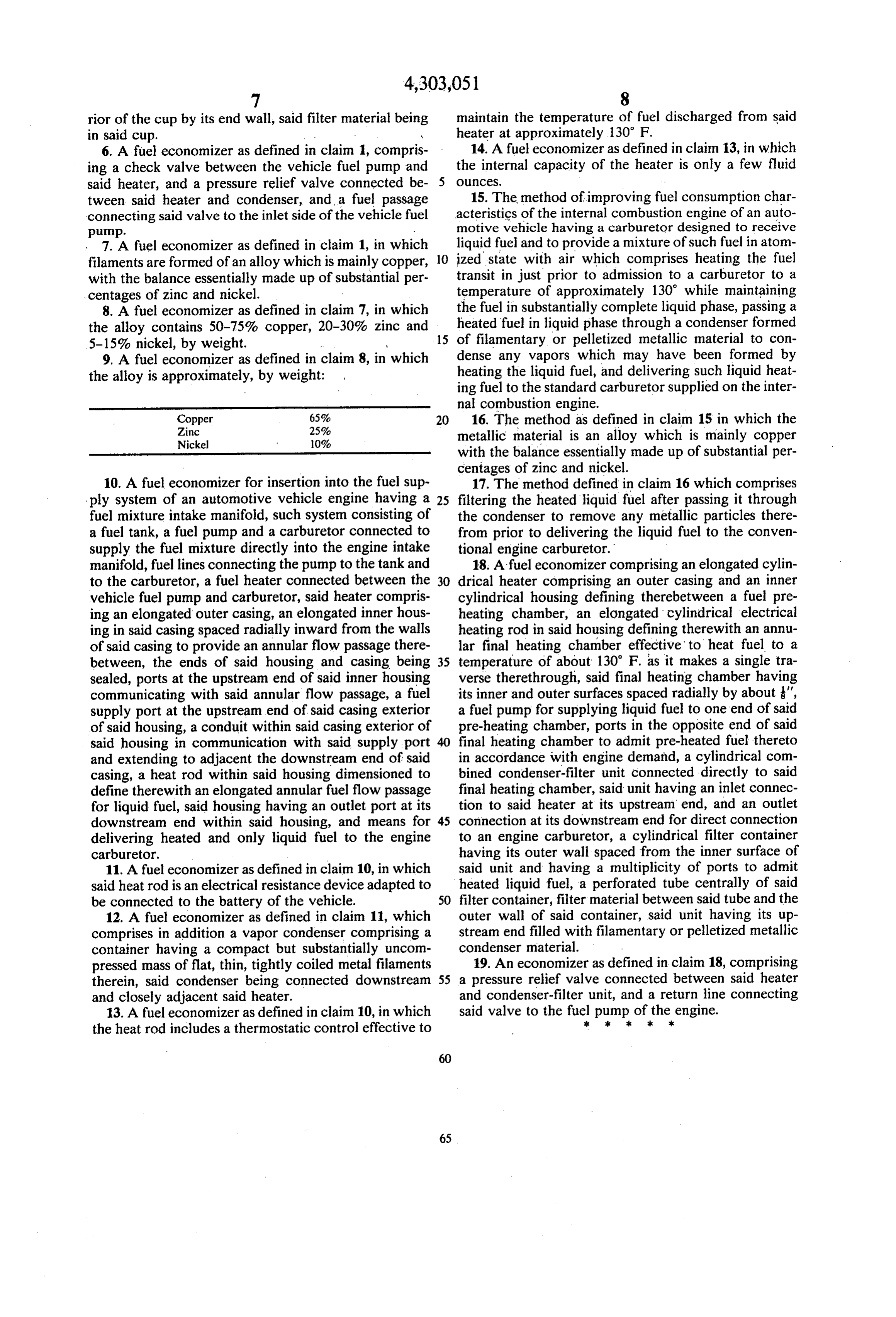
rior of the cup by its end wall, said filter material being maintain the temperature of fuel discharged from said in said cup. y heater at approximately 130 F. 6. A fuel economizer as defined in claim 1, compris 14. A fuel economizer as defined in claim i3, in which ing a check valve between the vehicle fuel pump and the internal capacity of the heater is only a few fluid said heater, and a pressure relief valve connected be- 5 OunCeS.
tween said heater and condenser, and, a fuel passage 15. The method of improving fuel consumption char connecting said valve to the inlet side of the vehicle fuel acteristics of the internal combustion engine of an auto pump. w motive vehicle having a carburetor designed to receive 7. A fuel economizer as defined in claim 1, in whic liquid fuel and to provide a mixture of such fuel in atom filaments are formed of an alloy which is mainly copper, 10 ized state with air which comprises heating the fuel with the balance essentially made up of substantial per transit in just prior to admission to a carburetor to a - centages of zinc and nickel. temperature of approximately 130 while maintaining 8. A fuel economizer as defined in claim 7, in which the fuel in substantially complete liquid phase, passing a the alloy contains 50-75% copper, 20-30% zinc and heated fuel in liquid phase through a condenser formed 5-15% nickel, by weight. 15 of filamentary or pelletized metallic material to con 9. A fuel economizer as defined in claim 8, in which dense any vapors which may have been formed by heating the liquid fuel, and delivering such liquid heat the alloy is approximately, by weight:
ing fuel to the standard carburetor supplied on the inter
nal combustion engine.
16. The method as defined in claim 15 in which the
Nickel 0% metallic material is an alloy which is mainly copper with the balance essentially made up of substantial per centages of zinc and nickel.
10. A fuel economizer for insertion into the fuel sup 17. The method defined in claim 16 which comprises ply system of an automotive vehicle engine having a 25 filtering the heated liquid fuel after passing it through fuel mixture intake manifold, such system consisting of the condenser to remove any metallic particles there a fuel tank, a fuel pump and a carburetor connected to from prior to delivering the liquid fuel to the conven supply the fuel mixture directly into the engine intake tional engine carburetor.
manifold, fuel lines connecting the pump to the tank and 18. A fuel economizer comprising an elongated cylin to the carburetor, a fuel heater connected between the 30 drical heater comprising an outer casing and an inner vehicle fuel pump and carburetor, said heater compris cylindrical housing defining therebetween a fuel pre ing an elongated outer casing, an elongated inner hous heating chamber, an elongated cylindrical electrical ing in said casing spaced radially inward from the walls heating rod in said housing defining therewith an annu of said casing to provide an annular flow passage there lar final heating chamber effective to heat fuel to a between, the ends of said housing and casing being 35 temperature of about 130 F. as it makes a single tra sealed, ports at the upstream end of said inner housing verse therethrough, said final heating chamber having communicating with said annular flow passage, a fuel its inner and outer surfaces spaced radially by about ", supply port at the upstream end of said casing exterior a fuel pump for supplying liquid fuel to one end of said of said housing, a conduit within said casing exterior of pre-heating chamber, ports in the opposite end of said said housing in communication with said supply port 40 final heating chamber to admit pre-heated fuel thereto and extending to adjacent the downstream end of said in accordance with engine demand, a cylindrical com casing, a heat rod within said housing dimensioned to bined condenser-filter unit connected directly to said define therewith an elongated annular fuel flow passage final heating chamber, said unit having an inlet connec for liquid fuel, said housing having an outlet port at its tion to said heater at its upstream end, and an outlet downstream end within said housing, and means for 45 connection at its downstream end for direct connection delivering heated and only liquid fuel to the engine to an engine carburetor, a cylindrical filter container carburetor. having its outer wall spaced from the inner surface of 11. A fuel economizer as defined in claim 10, in which said unit and having a multiplicity of ports to admit said heat rod is an electrical resistance device adapted to heated liquid fuel, a perforated tube centrally of said be connected to the battery of the vehicle. 50 filter container, filter material between said tube and the 12. A fuel economizer as defined in claim 11, which outer wall of said container, said unit having its up comprises in addition a vapor condenser comprising a stream end filled with filamentary or pelletized metallic container having a compact but substantially uncom condenser material.
pressed mass of flat, thin, tightly coiled metal filaments 19. An economizer as defined in claim 18, comprising therein, said condenser being connected downstream 55 a pressure relief valve connected between said heater and closely adjacent said heater. and condenser-filter unit, and a return line connecting 13. A fuel economizer as defined in claim 10, in which said valve to the fuels pump : xk of kthe2. engine.
the heat rod includes a thermostatic control effective to
Provenance
- Collection
- Cited prior art
- Original PDF
- patentimages.storage.googleapis.com →
- Filed
- 1977-05-09
- Pages
- 7
- Method
- pdftotext (the PDF's own text layer) + pdftoppm 300dpi page scans
- Source
- Google Patents bibliographic record
- Granted
- 1981-12-01
- Inventors
- Rainer E. Weishaar; MICHIGAN MOTOR CORP
- Transcribed from
- patentimages.storage.googleapis.com →