patent · US5373825
Internal combustion engines
20 December 1994
Page 1 — bibliographic record
United States Patent (19) 11 Patent Number: 5,373,825 Stephens et al. 45 Date of Patent: Dec. 20, 1994 54 INTERNAL COMBUSTION ENGINES 4,315,490 2/1982 Webber et al. ..................... 123/549 4,338,905 7/1982 Urich................ ... 123/525 75) Inventors: Robert Stephens, Birmingham; 4,356,805 11/1982 Kler ...... ... 123/525 Thomas Cox; David C. Cox, both of 4,370,970 2/1983 Kunz ................................... 123/557 Warley, all of England 4,398,523 8/1983 Henson ................................ 123/549 4,524,730 6/1985 Doell et al. ......................... 123/525 73) Assignee: Spirrit Environmental Technology 4,550,691 11/1985 McWade ............................. 123/525 Limited, Redditch, England 4,567,857 2/1986 Houseman et al. ................ 123/1 A 21) Appl. No.: 30,360 4,706,636 l/1987 Davis .................................. 123/54 4,748,961 6/1988 Headley et al. ... 123/557 22, PCT Filed: Sep. 18, 1991 4,784,092 11/1988 Pitti ...m. 123/525 (86 PCT No.: PCT/GB91/01601 FOREIGN PATENT DOCUMENTS S 371 Date: Mar. 17, 1993 2826976 3/1980 Germany .
87, PCT Pub. No.: WO92/05360 Primary Examiner-Tony M. Argenbright Assistant Examiner-M. Macy
PCT Pub. Date: Apr. 2, 1992 Attorney, Agent, or Firm-Renner, Kenner, Greive, 30) Foreign Application Priority Data Bobak, Taylor & Weber
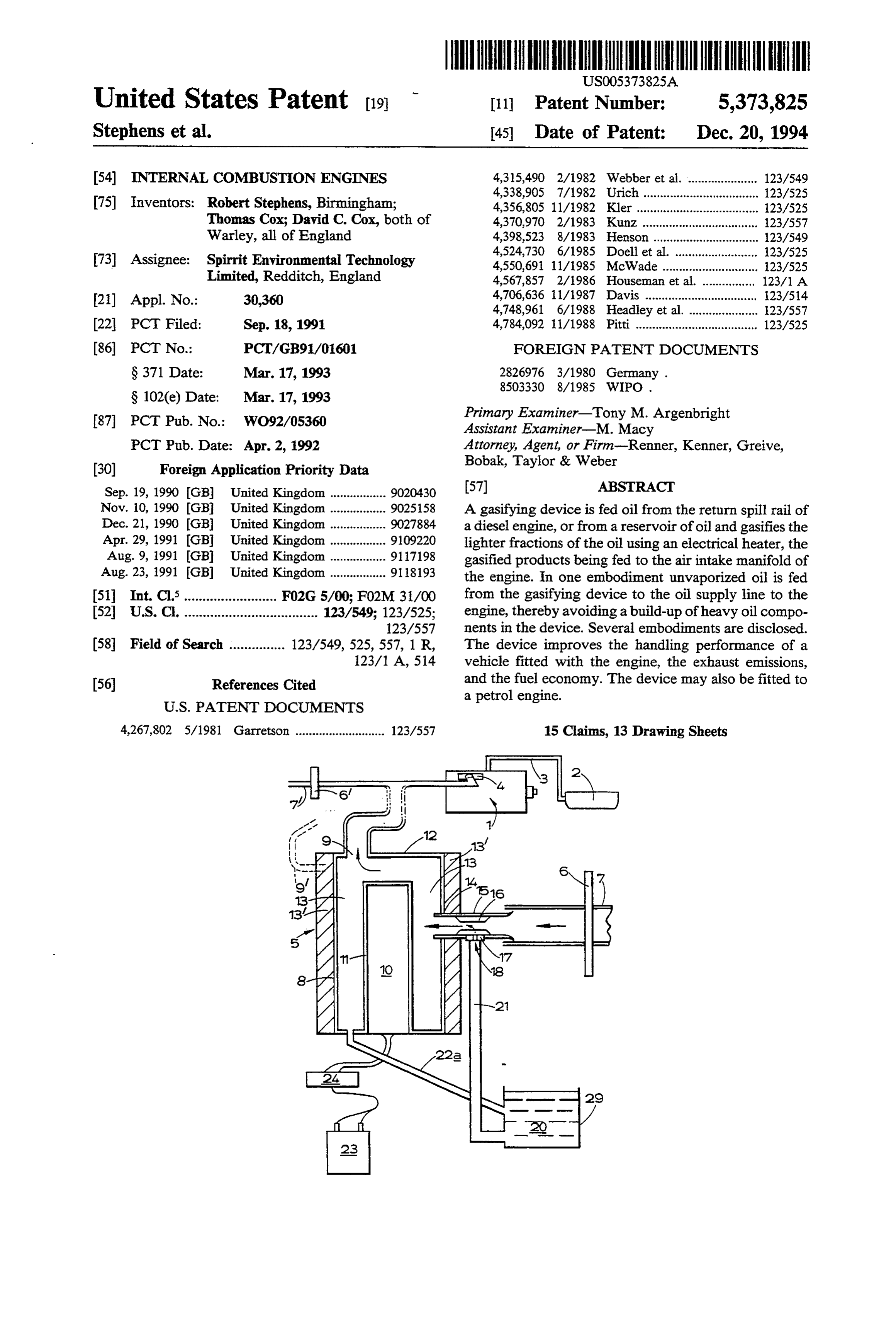
Sep. 19, 1990 GB United Kingdom ................. 9020430 57 ABSTRACT Nov. 10, 1990 GB United Kingdom ................. 9025158 A gasifying device is fed oil from the return spill rail of Dec. 21, 1990 GB United Kingdom ................. 9027884 a diesel engine, or from a reservoir of oil and gasifies the Apr. 29, 1991 GB United Kingdom ................. 9109220 lighter fractions of the oil using an electrical heater, the Aug. 9, 1991 GB United Kingdom ................. 91.17198 gasified products being fed to the air intake manifold of Aug. 23, 1991 (GB) United Kingdom ................. 911.8193 the engine. In one embodiment unvaporized oil is fed 511 Int. Cl.......................... F02G 5/00; F02M 31/00 from the gasifying device to the oil supply line to the 52 U.S. C. .................................... 123/549; 123/525; engine, thereby avoiding a build-up of heavy oil compo 123/557 nents in the device. Several embodiments are disclosed.
58 Field of Search ............... 123/549, 525,557, 1 R, The device improves the handling performance of a 123/1 A, 514 vehicle fitted with the engine, the exhaust emissions, (56) References Cited and the fuel economy. The device may also be fitted to a petrol engine.
4,267,802 5/1981 Garretson ........................... 123/557 15 Claims, 13 Drawing Sheets
Page 2
Drawing sheet — no readable text.
Page 3
Drawing sheet — no readable text.
Page 4
Drawing sheet — no readable text.
Page 5
Drawing sheet — no readable text.
Page 6
Drawing sheet — no readable text.
Page 7
Drawing sheet — no readable text.
Page 8
Drawing sheet — no readable text.
Page 9
Drawing sheet — no readable text.
Page 10
Drawing sheet — no readable text.
Page 11
Drawing sheet — no readable text.
Page 12
Drawing sheet — no readable text.
Page 13
Drawing sheet — no readable text.
Page 14
Drawing sheet — no readable text.
Page 15
stantially the same high temperature so that the oil
NTERNAL COMBUSTON ENGINES droplets entrained in the incoming air stream are gas ified at substantially the same temperature, no matter
This invention relates to internal combustion engines where they hit the sleeve. A portion of the oil (b.r and to add-on devices adapted to be used in conjunction 163-390° C. for some European diesel fuel) entering with them to improve their performance, and also to the chamber (annular space temperature substantially vehicles incorporating such engines. 250 C.) will be vaporised before reaching the surface of There have been very many proposals to provide an the sleeve.
add-on device to an internal combustion engine to in The chamber may be generally annular in a cross-sec prove its power, fuel economy, or reduce emissions. O tion and may be defined between the outer surface of One of the known proposals is that of French patent the sleeve and the inner surface of a surrounding wall. No. 576 434 which discloses a device which takes car The oil may be drawn from the vehicle's diesel fuel buretted fuel and passes it into an electrically heated tank, or from a reservoir of oil, and an oil return pas pipe so as to vaporise the droplets of fuel before deliver sageway may be provided from the chamber to the ing it to the engine. The engine can be run on light or 15 reservoir so that oil which condenses in the chamber, or heavy fuel, the electrical heater being disconnected which is not gasified, can be returned to the reservoir. when light fuel is used. The proposed device suffers This should not normally be necessary and can cause from the problem of coking up due to the deposition of problems with air entrainment.
unburned solid residue. The oil inlet orifice may be provided in a removable It is also known from GB 2 169 654 to provide a 20 component complex system to add mineral oil vapour to the air inlet orificessoofthat the device may be provided with oil different sizes for use with engines of inlet to an internal combustion engine, the mineral oil different capacities.
vapour being produced at a relatively low temperature The device may have a float chamber for oil, the fluid in a multiple turn helical coil. The mineral oil preferred by the proprietors of GB 2 169 654 is paraffin. This too 25 inletIn being fed from the float chamber.
another preferred embodiment the delivery means is liable to suffer from problems of coking up.
The present invention provides a relatively simple supplies oil to a pool or reservoir of oil in the volatising add-on device to improve the performance of an inter chamber heater.
which pool of oil is bodily heated by the nal combustion engine. Preferably the heater drives off the lighter compo According to a first aspect of the invention we pro 30 nents of the oil (when it is a mixture of components with vide a device for attachment to the air supply of an internal combustion engine, the device comprising different hind the boiling points, as is diesel oil) and leaves be heavier components.
chamber means defining a volatising chamber, an en ergy source provided in the chamber, fluid inlet means control The delivery means may include a float chamber to to the chamber, and a gas/vapour outlet from the cham 35 the depth of the pool of oil in the chamber. The ber, the fluid inlet means comprising air inlet means for volatising chamber may have a mixing region in which admitting air to the chamber and delivery means for vapours driven off from the oil in the chamber mix with delivering hydrocarbons, hereinafter referred to as oil, inlet.or are entrained in air entering the chamber via an air to the chamber, the arrangement being such that oil entering the chamber is gasified in the chamber and the The delivery means may be fed oil from a fuel return air/gasified oil mixture leaves the chamber via the gas/- line leading from the engine. vapour outlet, the gas/vapour outlet being adapted for The heater preferably extends in the pool of oil at an connection to the air supply of an internal combustion angle to the surface of the pool. The heater is preferably engine. provided at or near the surface of the pool and may dip Preferably the energy source is an electrical heater or 45 into the pool from above.
glow plug. Inclining the heater relative to the surface of the pool It has been found that adding gasified oil to the air increases the surface area of the heater in the surface drawn into an engine improves the burning of the con region of the pool, which can improve the boiling of the ventional petrol or diesel fuel in the engine. In many light fractions of the oil in the surface region of the engines the conventional fuel can be more completely 50 pool. The heater may be provided in a bore formed in a burned when the gasified oil is added. housing or body defining the pool and/or mixing re Preferably the oil which is added is diesel fuel oil, but gon.
a range of hydrocarbons can be totally gasified by ap Alternatively the level of the oil may be controlled so propriate selection of the power of the electrical heater. as to substantially cover the hot portions of the heater. In a preferred embodiment the delivery means deliv 55 A liquid oil extraction line may be provided to enable ers the oil in droplets to the chamber. The delivery oil in the pool to leave the chamber whilst still liquid. means preferably adds the oil to the air before it enters The extraction line is preferably provided at or towards the chamber. the bottom of the chamber, and may deliver oil (possi An outer chamber containing the oil may surround bly via an electric pump) to the main fuel tank or the the volatilising chamber. normal fuel line to the engine, preferably downstream The fluid inlet may comprise a venturi or the like of a fuel filter. In the latter way heated liquid oil from which creates suction adjacent an oil inlet orifice of the the chamber is added to the fuel normally entering the venturi thereby drawing oil into a stream of air entering engine in the conventional way (as well as gasified oil the chamber. The oil inlet may be at about the mid-point being added to the air entering the intake manifold). of a venturi restriction. The oil may be pre-heated be 65 Problems associated with the build up of residues may fore it enters the venturi. be alleviated by such a construction since the heavier The heater may be surrounded by a metal sleeve. The components of the oil are generally not re-circulated to sleeve may serve to create a large area of metal at sub undergo a subsequent gasification heating, but are in
Page 16
stead burned. Thus oil in the fuel tank is broadly speak preferably in the range 333:1 to 33:1. In one example ing only heated once. trial a petrol engine was at the higher end of this range The level of oil in the pool is preferably at least about and a diesel engine at the lower end. 15mm above the inlet of oil to the pool and most prefer We may have a vapour outlet pipe which is adjust ably about 15 to 20, 20 to 25 or 25-30 mm above the oil able or variable relative to the pool (for example of inlet. The inlet of oil to the pool is preferably via a small variable height). This adjustment may be done as the bore pipe. device is fitted to the engine, the outlet tube thereafter These measures help to reduce the chance of air bub being in a fixed position. The height of the tube is nor bles being entrained in the liquid oil extracted from the mally determined by experiment and usually depends pool, which can be important when the extracted oil 10 upon the engine's suction. Alternatively, the outlet pipe reaches the injector pump for delivery to the engine. If could be truely adjustable, even after fitting to the en the injector pump is not "self-bleeding” it is best to gine.
return oil from the heater to the vehicle's fuel tank. The gas/vapour outlet is in most cases preferably Alternatively the extraction line may deliver oil to a spaced from the surface of the pool of oil by between reservoir, which may be the same reservoir as that 15 about 25 mm to 50 mm; for wider bore gas/vapour which provides the oil to the delivery means. Thus outlets this space could be reduced. If the outlet is too unvaporised oil may be recirculated, but in order to close to the surface of the pool we have found that the avoid a build-up of involatile material it is desirable vapour which is drawn off is too "wet'-it contains a periodically to renew the oil in the reservoir (exchange very fine mist of droplets of oil. Wet vapour has been it for fresh oil). 20 found to be undesirable in certain circumstances since it A pump may be provided to extract liquid oil from might result in deposits and residues in the flow path the volatising chamber via the extraction line and pref from the device to the engine's cylinders and may cause erably should be provided with a cooling coil. The substantial dilution of the engine's sump oil. pump may be controlled by an electronic controller If the outlet is too far away from the surface of the which may be arranged to keep the temperature of the 25 pool we have found that there seems to be a marked oil in the pool substantially constant by controlling the reduction in the amount of oil vapours sucked up by the pump and/or the heater. The temperature is preferably engine. Both of these phenomena are somewhat surpris kept at about 210 C.-280 C., and more preferably at 1ng.
230 C-260° C., and most preferably at about 250 C. Preferably the outlet comprises a tube extending into The volume of oil in the pool is preferably only a few 30 a main body defining the volatising chamber. The body cubic centimeters, for example 5-25 cc, most preferably preferably defines the air inlet means which is prefera about 10 cc a few cc. bly above the level of the bottom of the tube. This enables the heater to produce gasified oil in a When the delivery means includes a float chamber, short time (for example 5-25 seconds) and so avoids a for example to control the level of oil in the pool of oil, long warm-up time for the device when the engine is 35 the float chamber may be defined in the body of the first started. device, for example by a float chamber housing at The path for liquid oil leaving the pool preferably tached to a vaporisation chamber housing. includes a restrictor to limit the flow rate of liquid oil. According to a second aspect the invention consists There is also preferably a filter up stream of the restric in an internal combustion engine having a device in tor to protect the restrictor from blockage. Such a re accordance with the first aspect of the invention, the strictor also allows the flow rate to be varied by varying device introducing a mixture of air and gasified oil into the size of the restrictor. The balance of flows of liquid the air inlet of the engine, and the engine being fed oil into and out of the volatising chamber are governed conventional petrol or diesel oil fuel by its carburettor by the rate of supply to the float chamber and the re or fuel injector means.
strictor(s) in the exit line, for a given pump. According to a further aspect of the invention we The ratio of oil leaving the pool as liquid to that provide a multi-cylinder internal combustion engine leaving as gasified oil is preferably in the range, 50:1 to which comprises, in combination:
10:1. (a) means for conducting a gasified hydrocarbon fluid In general, the greater the flow-through of liquid in or fluid derivative thereof, including air to each of the pool the better, but there can be refinements on this SO said engine cylinders;
general concept. (b) an electrical heater;
We may wish to control the viscosity of oil entering (c) a main fuel tankfor the storage and carriage of the the pool, and/or the system's pump, so as to achieve a fuel which is burnt in said cylinders in order to more constant viscosity of oil, and hence more uniform produce heat which is converted into mechanical flow characteristics (the temperature of oil entering the 55 power and to supply fluid for gasification when the pool can vary according to the operating conditions and fuel is diesel oil;
history of the engine if no control is provided). We may (d) a heated chamber containing the said heater sup chose to control the viscosity of the oil by controlling plied with said fluid from the main fuel storage the temperature of the oil entering or leaving the pool, tank, or from an auxiliary storage tank, by way of for example by providing a secondary heater in the a float chamber connected to said heated chamber, liquid oil supply line to the pool. via an emulsion tube which is connected to a main The control of the temperature of the oil entering the air inlet to the chamber, the emulsion tube giving pool over the operating conditions of the engine could added control over the system's input offluid drop additionally or alternatively be achieved by insulation. lets and air to the said heated chamber; and The ratio of conventional fuel burned in the engine 65 (e) intermediate means connecting said engine cylin which enters the engine in the conventional way (such ders to said heated chamber and conducting gas as carburetted or injected petrol or injected diesel) to ified fluid from the said heated chamber to said that burned entering the engine as a gas or vapour is engine cylinders; whereby said fluid which passes
Page 17
into said heated chamber is gasified therein, the internal combustion engine comprising adding gasified gasified fluid thereafter passing through the inter diesel oil to the air which is a component of the fuel/air mediate means to said engine cylinders for burning charge which is burnt in the engine. with the fuel/air mixture. Preferably the gasified diesel oil is always available to It will be appreciated from the foregoing that we the air which is a component of the fuel/air combustion could provide the chamber as an enveloping chamber charge, rather than being supplied intermittently. so that the fluid is heated in the chamber before it is We were extremely surprised to find that normal delivered to the venturi or carburettor system. diesel DERV was the best fuel to gasify and add to the According to a still further aspect of the invention we air. We had previously thought that the best oil to use provide a generator for producing a gasified combus O was a relatively volatile oil, such as paraffin, and had tion promoter for an internal combustion engine; said gone to great expense to use only expensive mineral oils generator comprising a chamber containing an electri in our tests. The revelation that common (higher boil cal heater, said chamber being supplied with oil, the said ing) diesel DERV would not only work, but work fluids being introduced to said chamber by way of a much better than anything else we have tried was very float chamber feeding to a means with the fluid inlet 15 Surprising.
aperture and air-intake tube of a basic carburettor sys The method of improving the performance of an tem provided with an emulsion tube that gives added internal combustion engine may comprise improving its control over the input of said fluid droplets in air in fuel efficiency. Alternatively or additionally we may duced by the suction of the active engine to the said improve the exhaust emissions of the engine, and when heated chamber which means gasifies the said fluid 20 the engine is a diesel engine we may reduce the particu which is drawn by the engine's air suction into an inter late pollutants in the emissions. Additionally or alterna mediate means connected both to the said heated cham tively the method may improve the running of the en ber and to said engine for burning with the fuel/air gine and its delivery of power.
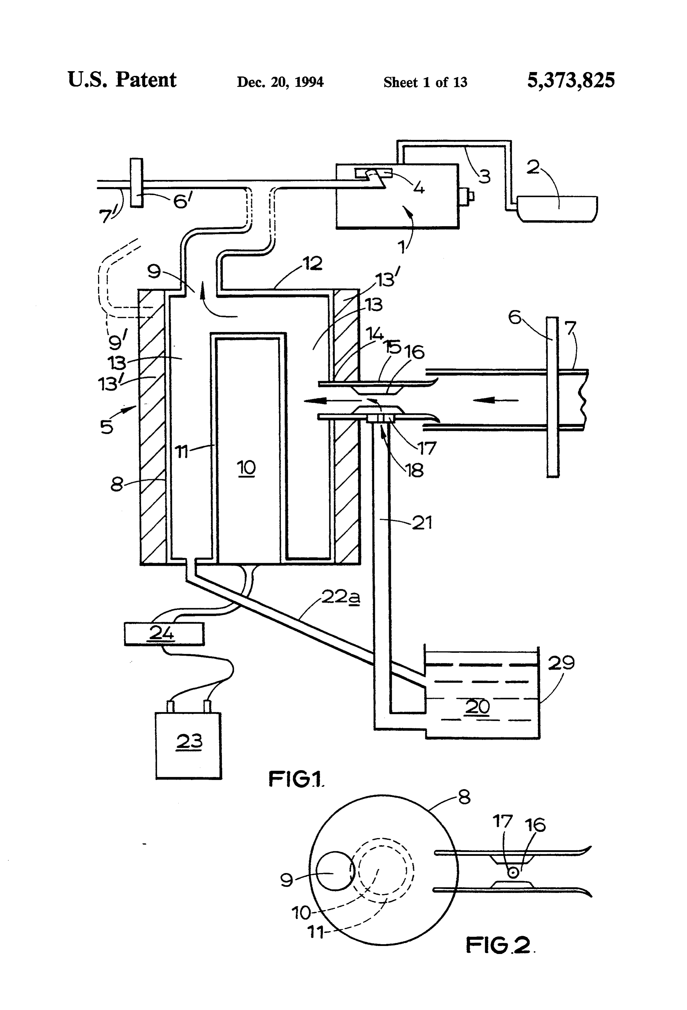
mixture. Some embodiments of the invention will now be When the engine is a diesel engine, the chamber may 25 described by way of example with reference to the be supplied with oil from the main fuel storage tank, or accompanying drawings of which:
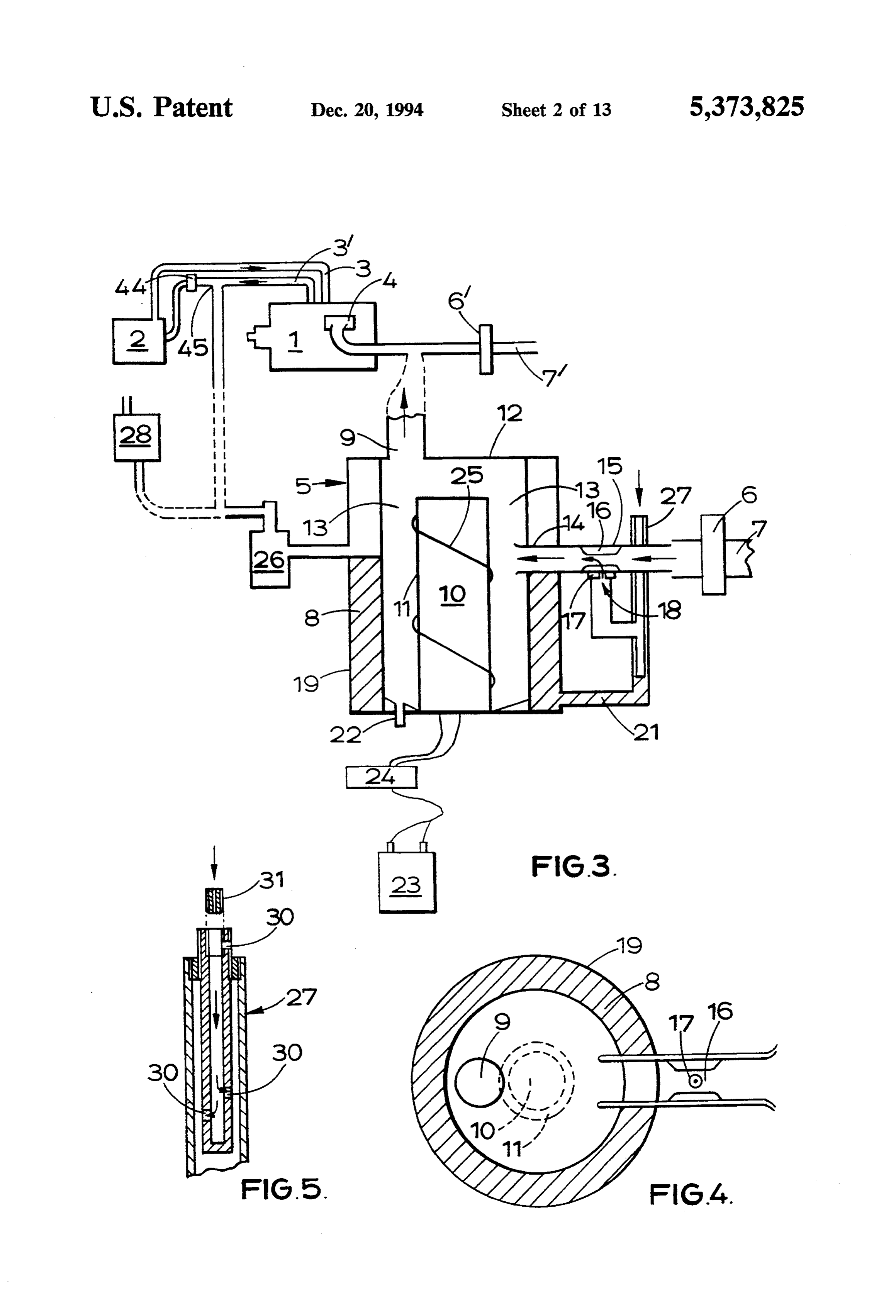
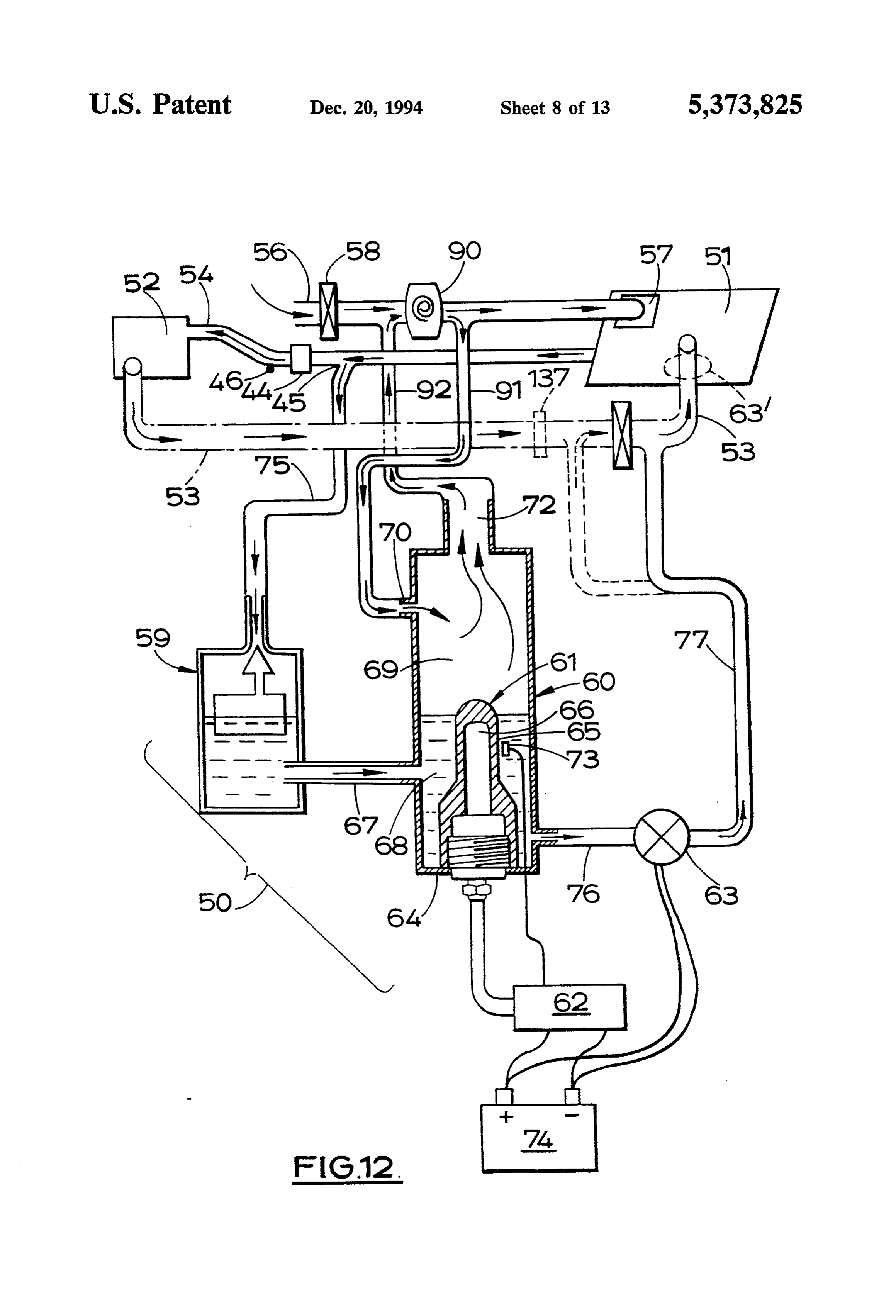
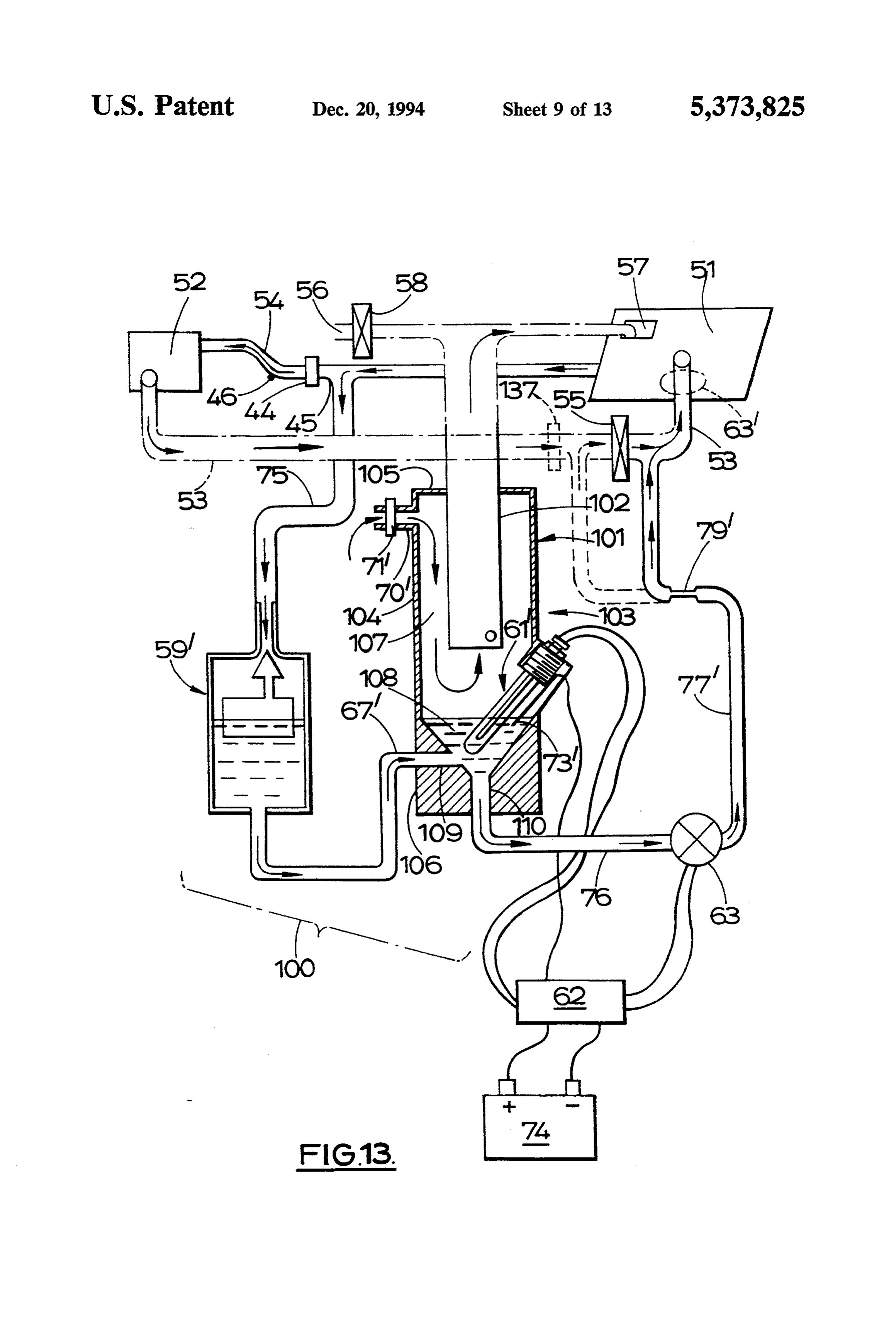
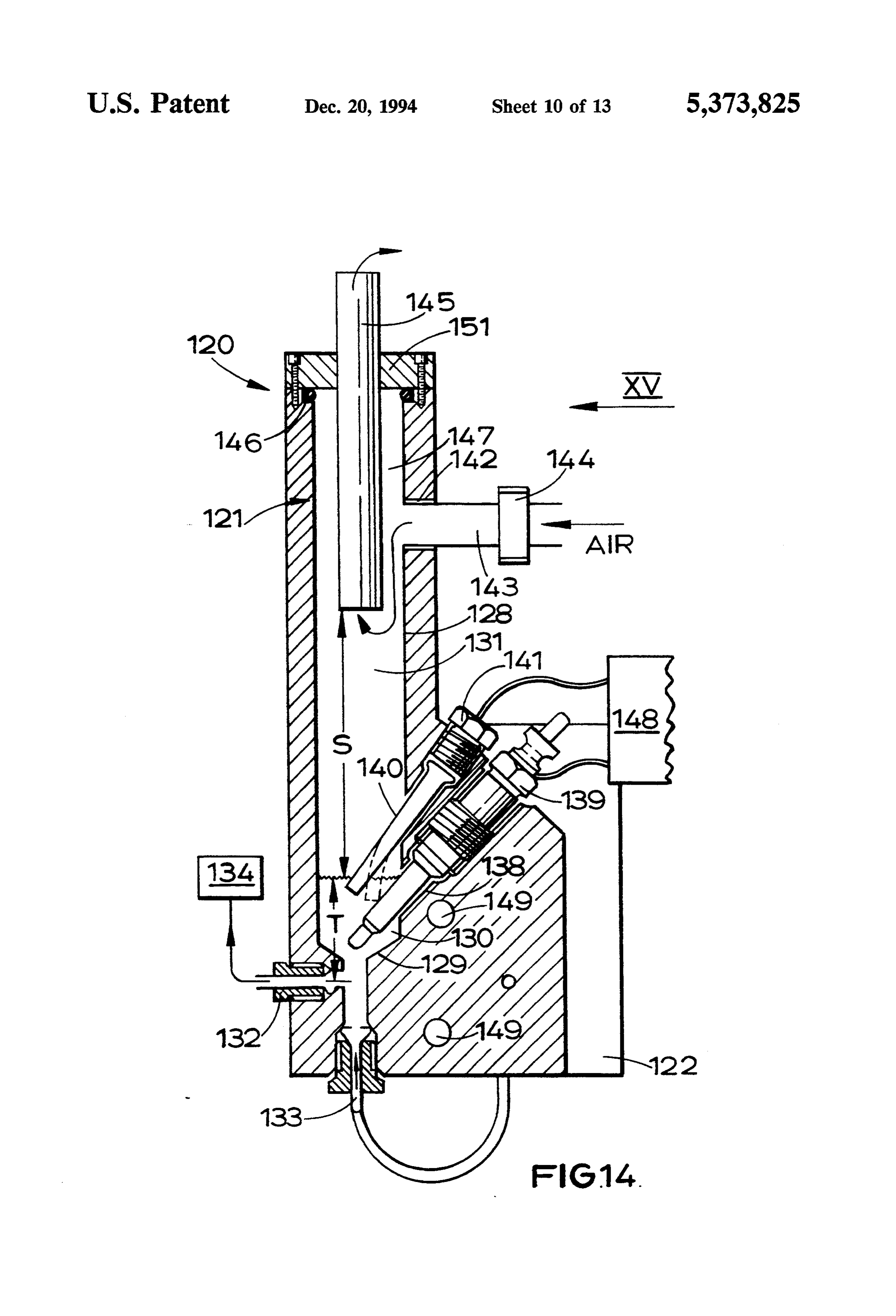
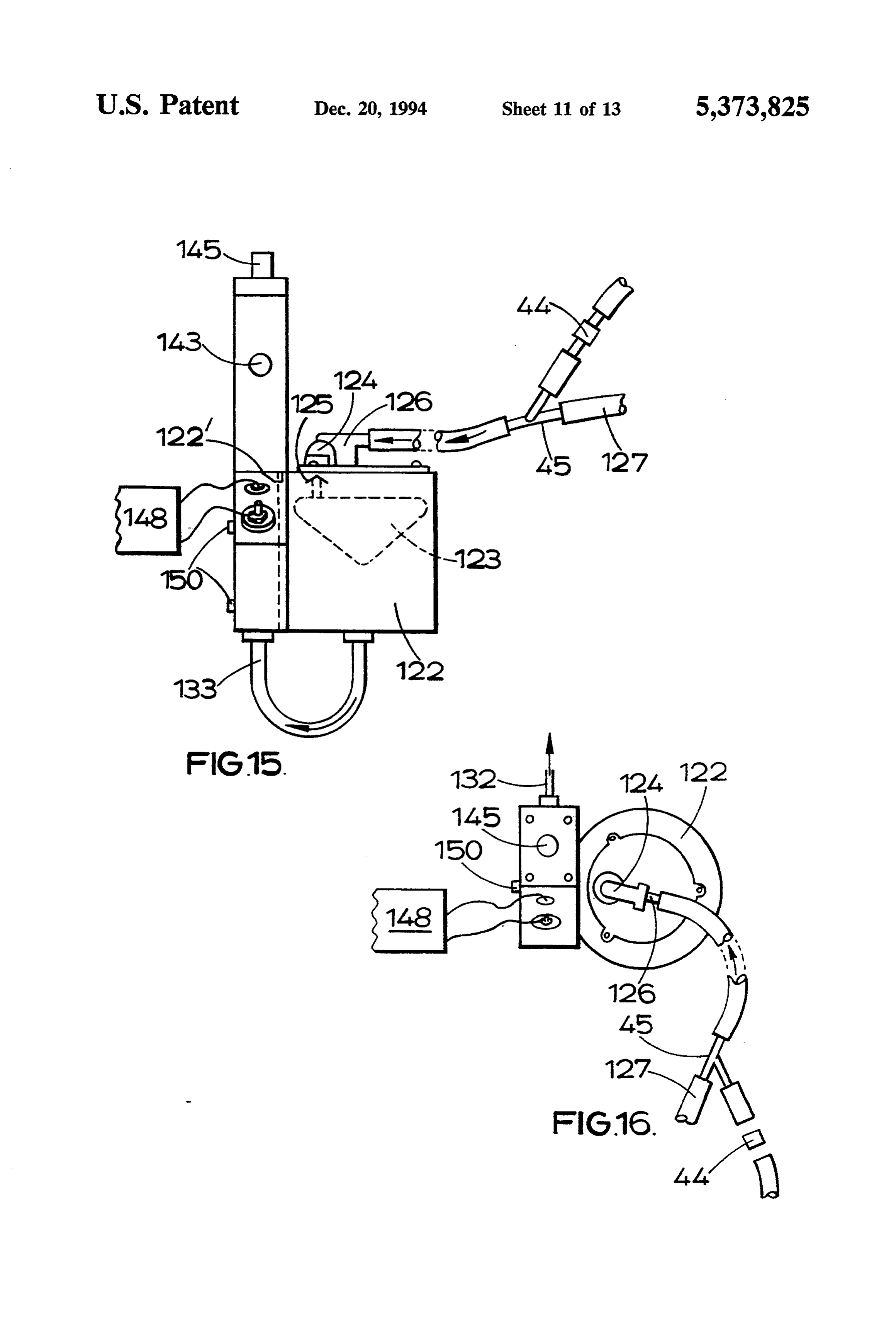
with an alternative hydrocarbon fluid or fluid deriva FIG. is a schematic illustration of a first device for tive thereof from an auxiliary storage tank. When the adding vaporised oil to the air taken into an internal main fuel is not diesel oil, the chamber is supplied with combustion engine, and an associated engine; diesel oil or with the alternative hydrocarbon from an 30 FIG. 2 is a schematic plan view of the device of FIG.
It will be appreciated that the chamber may surround FIG.3 shows a modification of the apparatus of FIG. or envelope the heater, and that the diesel oil may be 1;
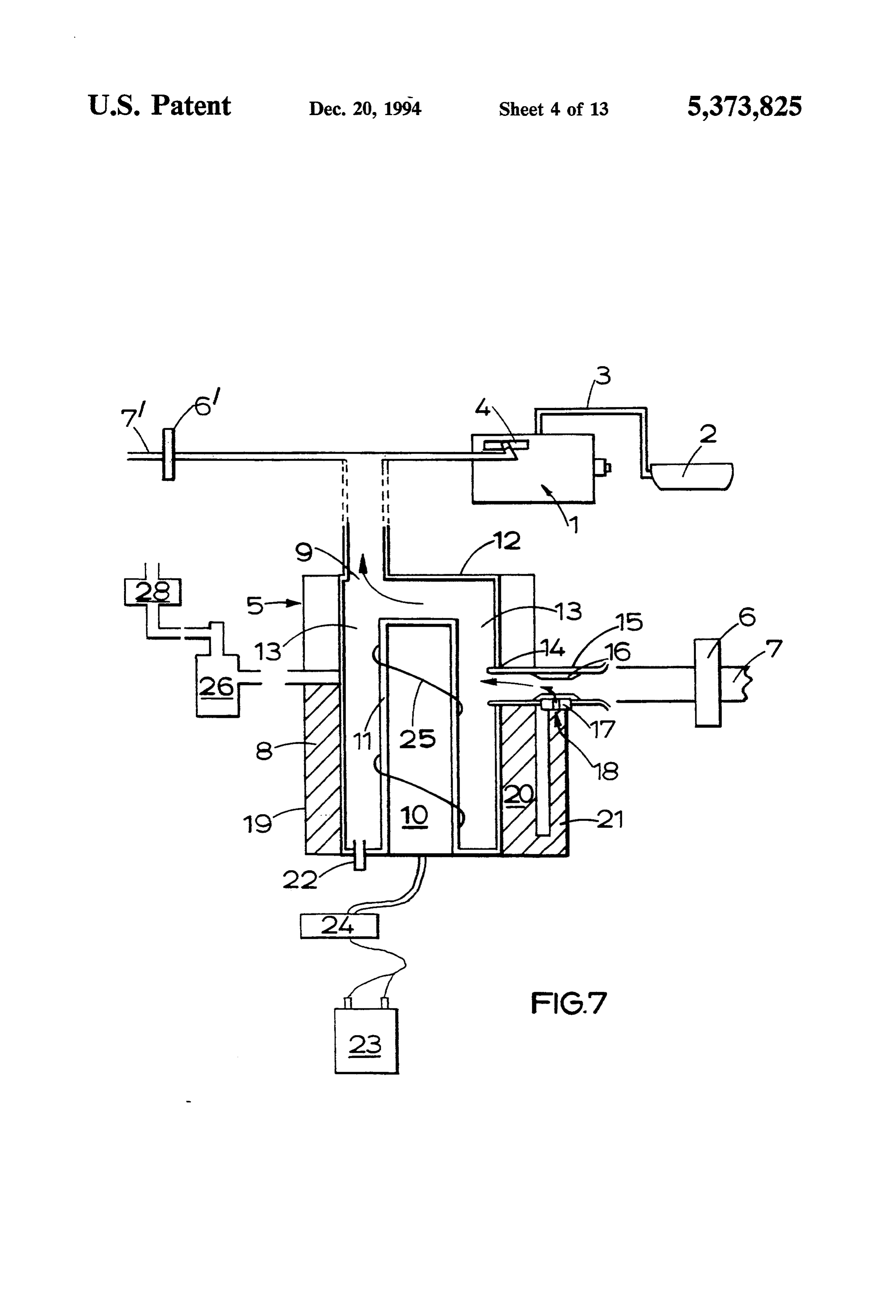
pre-heated before being vaporised or gasified. FIG. 4 is a schematic plan view of the device of FIG. According to a further aspect of the invention we 3;
provide an internal combustion engine having an air FIG. 5 is a view of an emulsion tube for the apparatus iniet, heating means for gasifying hydrocarbons, gas of FIGS. 1 and 2, the apparatus of FIGS. 3 and 4, and delivery means for delivery of gasified hydrocarbons FIGS. 6 and 7;
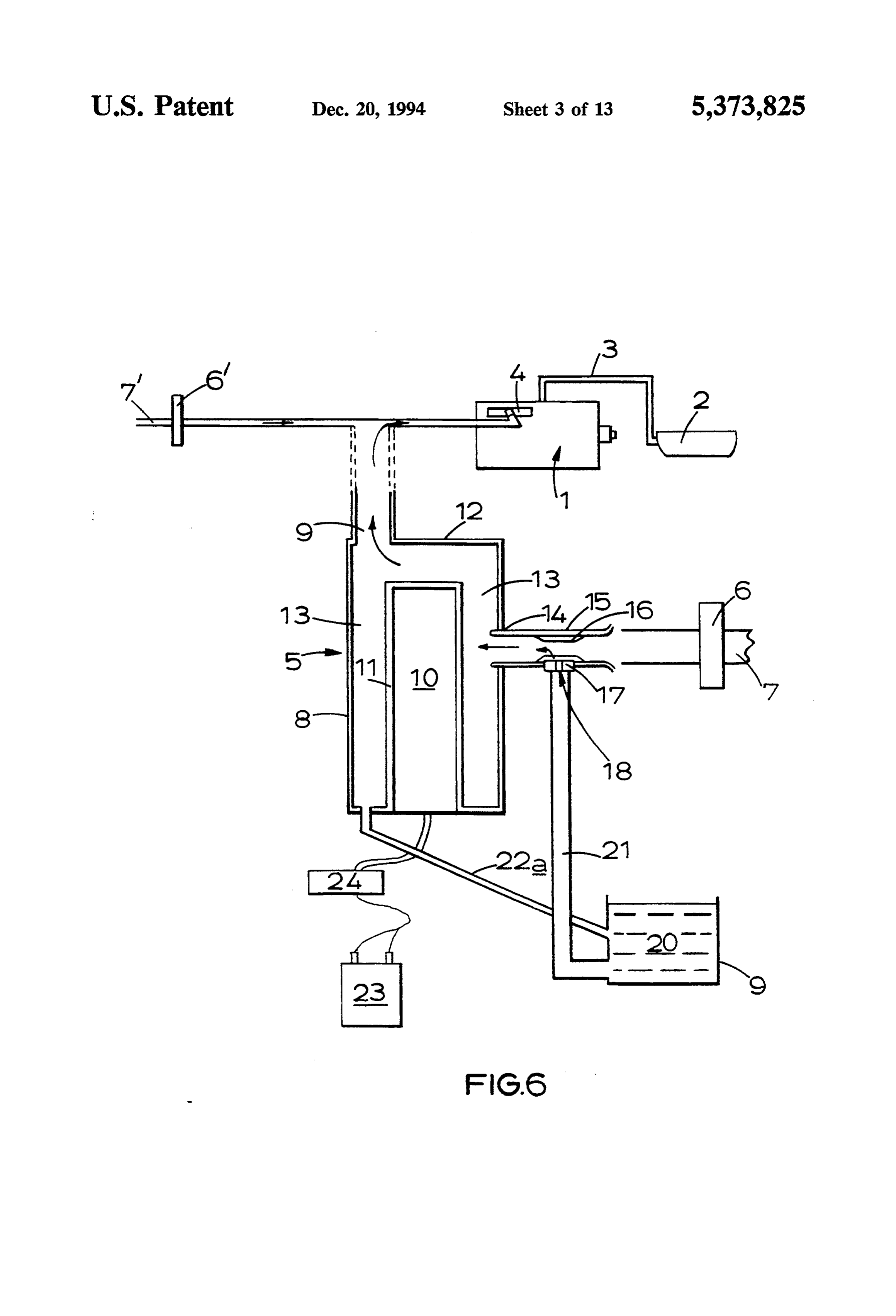
from the heating means to an air stream leading to the FIG. 6 shows a modification of the use of the device air inlet of the engine, entraining air supply means sup of FIGS. 1 and 2 in which the device is fitted to a petrol plying air to the heating means which air entrains gas engine instead of a diesel engine; ified hydrocarbons and leaves the heating means via the FIG. 7 shows a modification of the apparatus of gas delivery means, and pressure generating means for FIGS. 3-5;
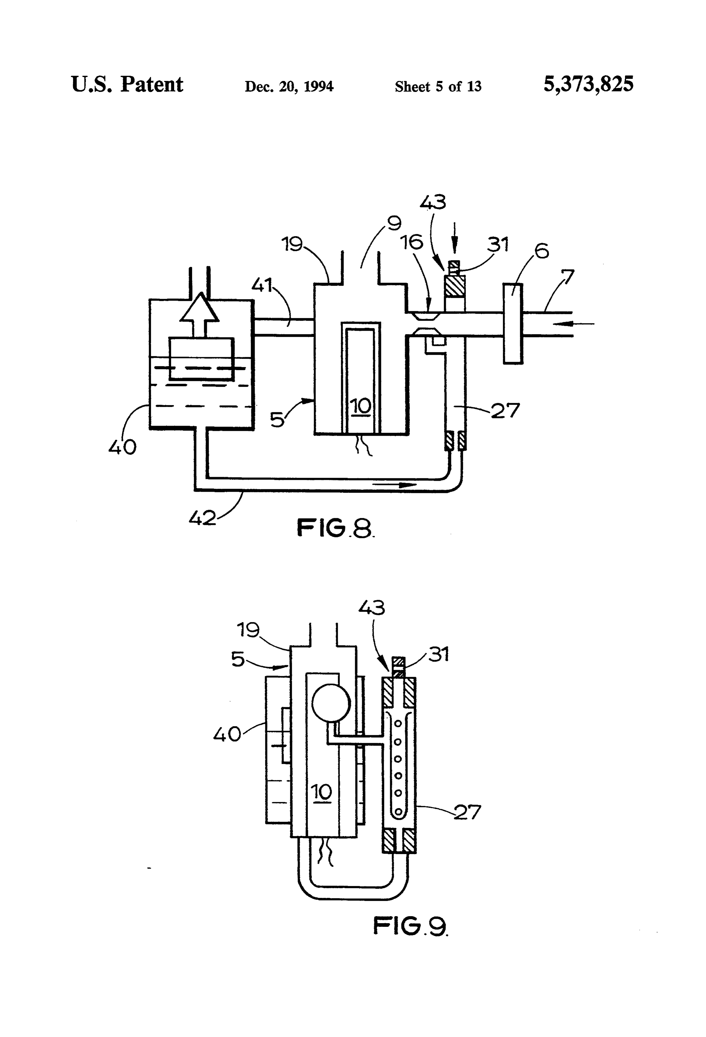
generating higher than atmospheric pressure; the en FIGS. 8 and 9 illustrate schematically combined float training air supply means collecting air at higher than 45 chamber and gasifier unit;
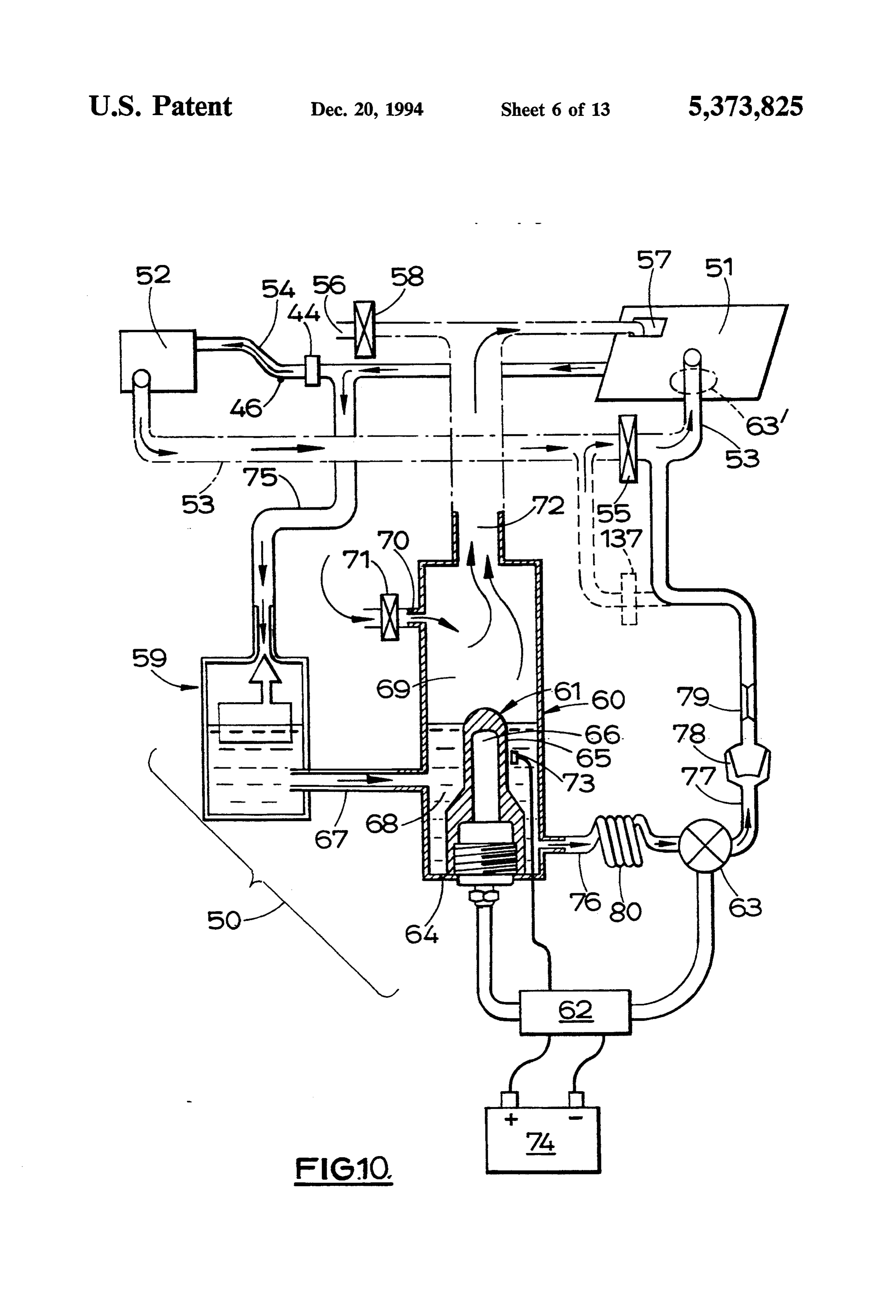
atmospheric pressure from the pressure generating FIG. 10 shows schematically a diesel engine fitted means and blowing it into the heating means. with a different gasifying device; Preferably the pressure generating means comprises FIG. 11 shows a petrol engine fitted with the gasify air compression means, such as a turbocharger or super ing device of FIG. 10;
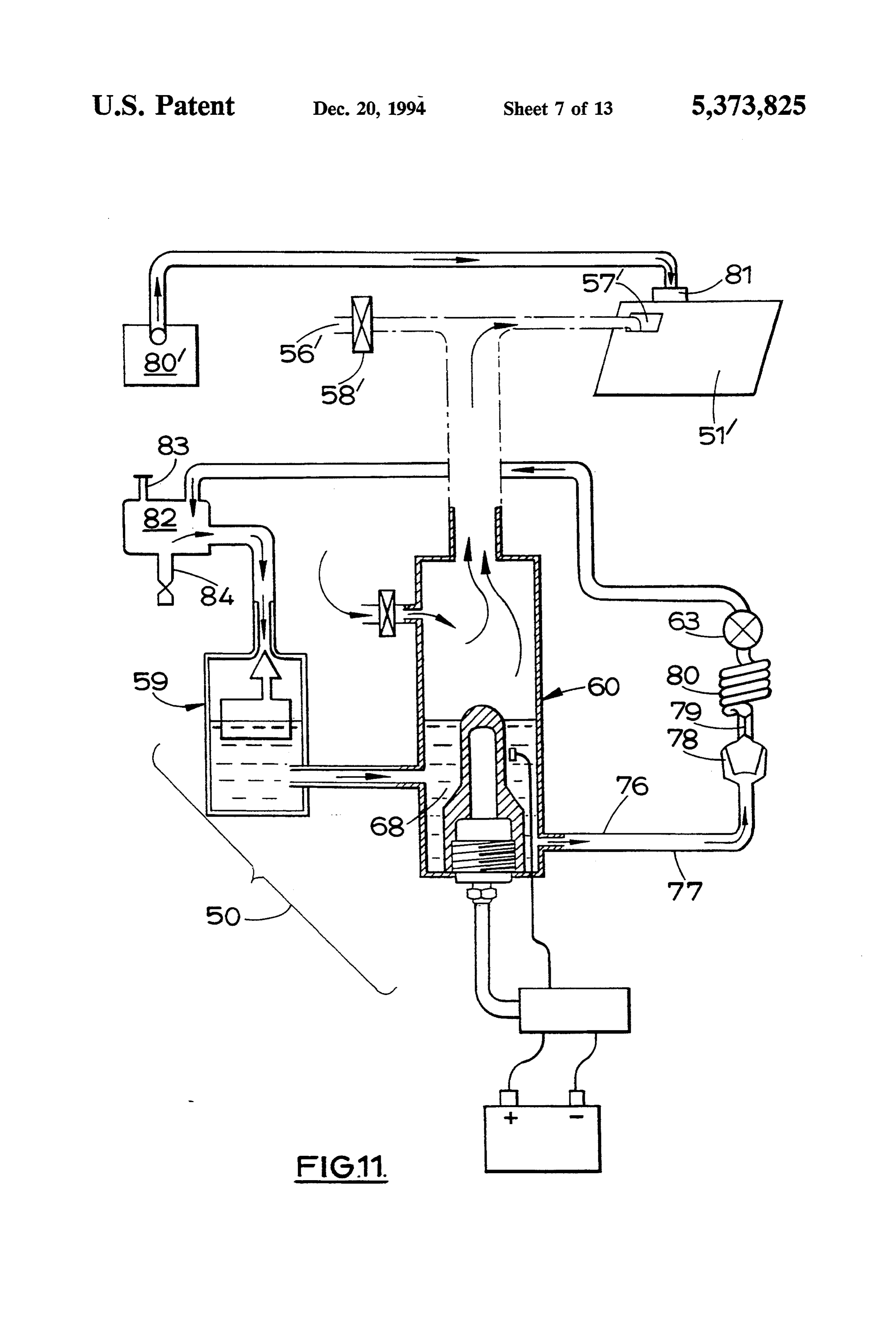
charger, provided in a main air inlet line leading to the 50 FIG. 12 schematically shows the gasifying device of air inlet of the engine; the entraining air supply means FIG. 10 fitted to a turbo charged diesel engine; taking relatively high pressure air from the main air FIG. 13 schematically shows a diesel engine fitted inlet line downstream of the air compression means. with a gasifying device similar to that of FIG. 10; Thus the air is blown into the heating means, prefera FIG. 14 is a cross section through production version bly through a controlling restrictor. 55 of a gasifying device;
Preferably the delivery means delivers gasified hy FIG. 15 shows a side view of the device of FIG. 14 as drocarbons to the main air supply line upstream of the viewed along arrow XV:
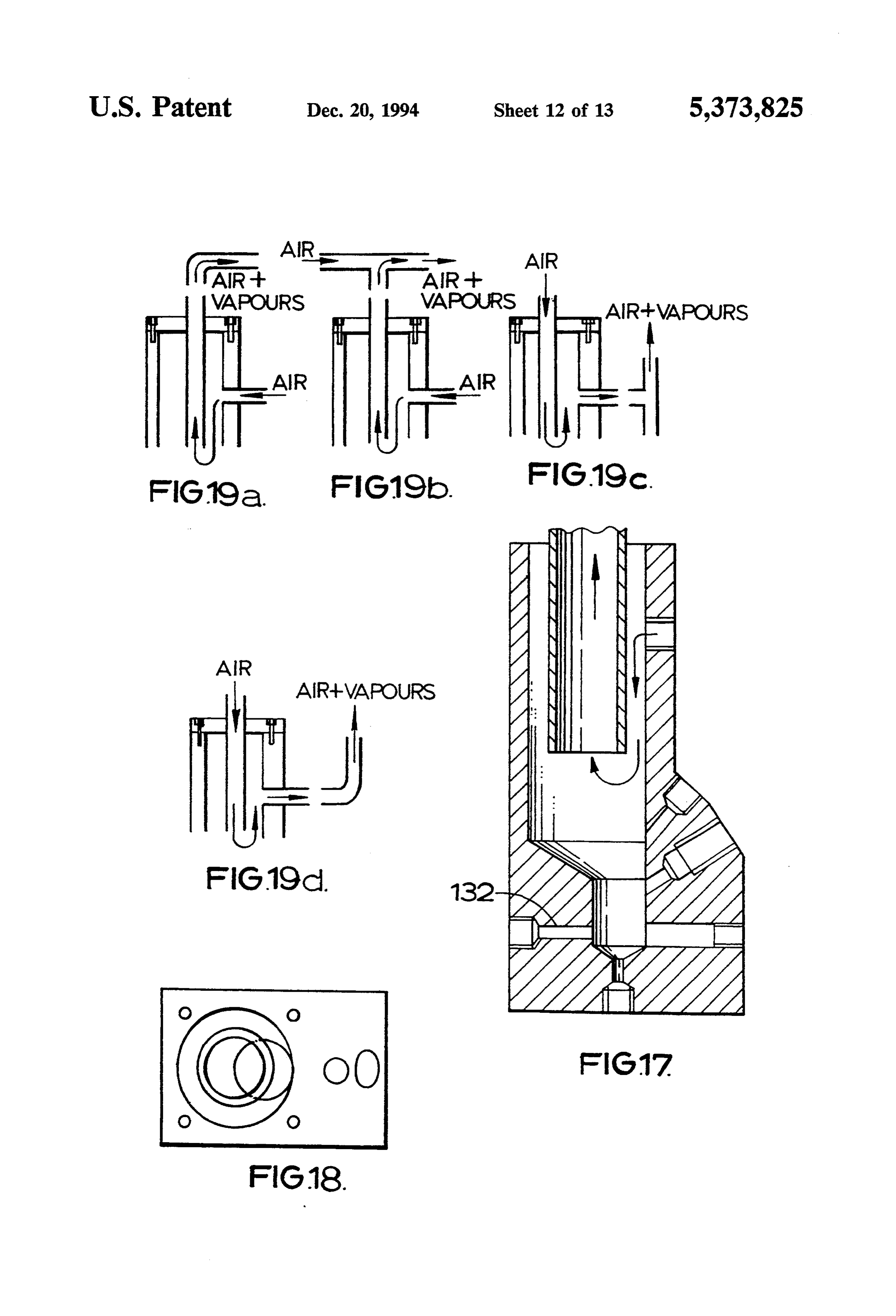
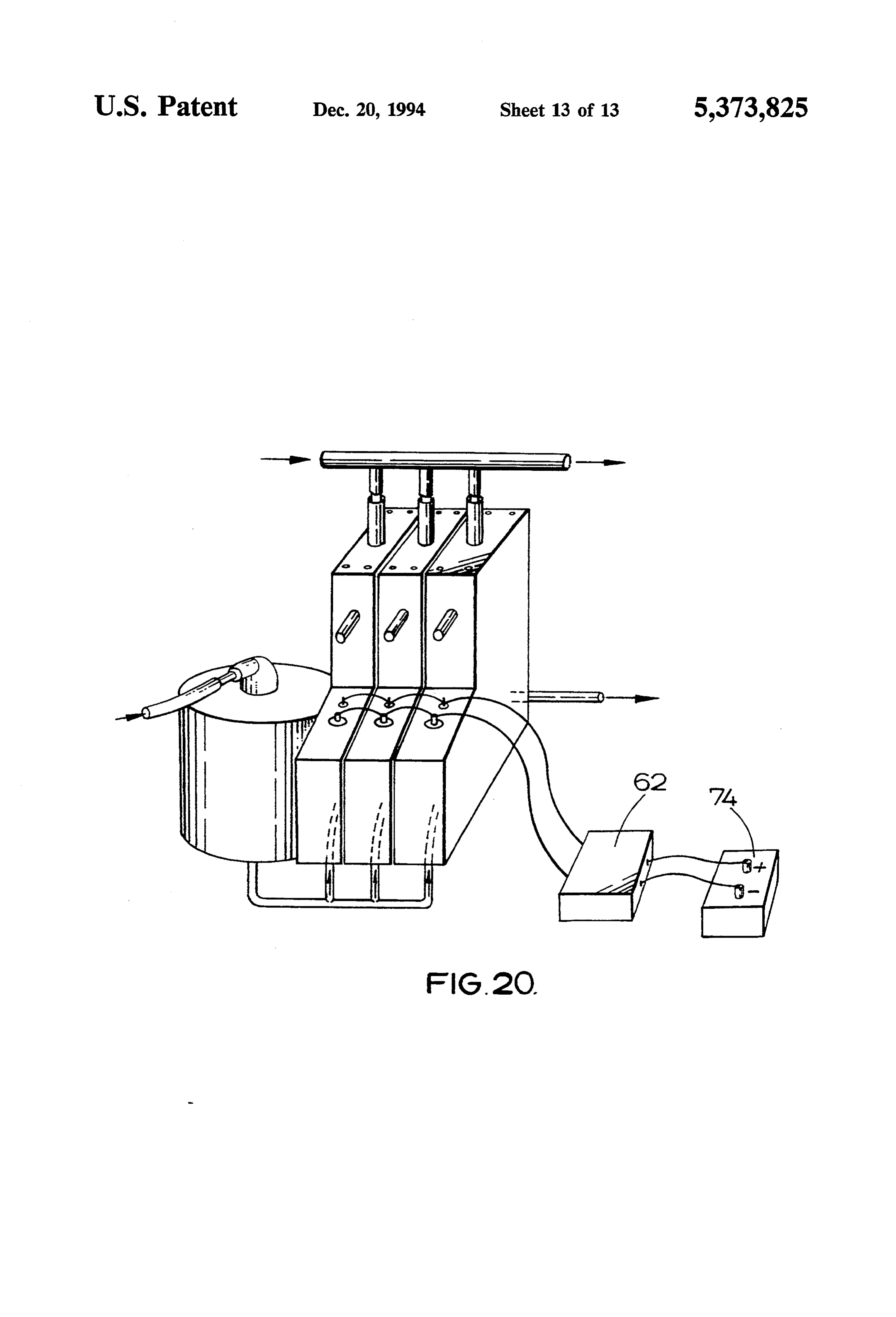
compression means. FIG. 16 shows a top view of the device of FIG. 14; Alternatively the pressure generating means may FIGS. 17 and 18 show cross-section and plan view of comprise a fan gr other impeller provided adjacent the a modified gasifying device;
air supply entraining means. In such an arrangement FIGS. 19a to 19d show schematically different air there need be no turbocharger to provide higher than flows which are possible for devices similar to that of atmospheric pressure. FIG. 14; and
Preferably the heating means comprises a device or FIG. 20 illustrates another modified device. generator in accordance with a preceding aspect of the 65 An internal combustion engine 1 of a vehicle (not invention. shown) is schematically illustrated in FIG. 1 and is fed According to yet another aspect the invention com diesel fuel from a fuel tank 2 via pipeworks 3 and a fuel prises a method of improving the performance of an injector (not shown). The engine 1 has an air intake
Page 18
manifold 4 to which is attached a performance enhanc Thus the air which enters the chamber 13 has drop ing device 5 interposed between the air intake manifold lets of oil and some vapour therefrom entrained in it. 4 and an air filter 6, provided in an air intake pipe 7'. The air and its entrained vapour and droplets of oil are The device 5 has its own air inlet pipe 7 and associated heated in the annular space of chamber 13 to about 250 filter 6, as will be described later. C. when the heater 10 is set at the upper end of its The device 5 comprises a cylindrical body 8 having temperature range, even though the heater itself is at a an outlet 9 at its top connected to the air intake manifold higher temperature. Any oil droplets which strike the 4. A cylindrical heater 10 extends from the base of the sleeve 11 are gasified.
body 8 towards the top and is centrally disposed in the The entraining air which enters the engine 1 carries a body. A tubular metal sleeve 11 completely surrounds O proportion of gasified oil that is dependent on the the heater 10. The body 8 has a top wall 12. An annular chosen temperature of the heater and the aspiration rate space 13 is defined between the sleeve 11 and the body of the engine which is a product of the engine's swept 8. The body 8 has an aperture 14 in its side wall through volume and rate of revolution. The temperature of the which a tube 15 projects into the space 13 at a plan air entraining the gasified oil between the gasifying position diametrically opposed from the plan position of 15 chamber outlet 9 and the manifold 4 is not sufficient to the outlet 9. The tube 15 contains a restricted passage diminish the volumetric efficiency of the engine signifi way 16 and is connected to the downstream side of the cantly.
air inlet pipe 7 of the device and the device's air inlet Gasified oil and air enter the intake manifold 4 and filter 6. this mixture improves the fuel efficiency of the engine 1 The wall of the tube 15 has a circular screw-in plug 20 in a way which is not entirely understood, but in a 17 at the centre of the region of the tube 15 which compression-ignition engine is likely to involve a reduc defines the restricted passageway 16. The plug 17 has an tion in the delay between fuel injection and fuel igni oil-inlet aperture 18 which is in communication with a tion. It is generally accepted that optimum diesel engine reservoir 29 of oil 20 via an oil-supply pipe 21. An oil performance is realised when combustion completed as spill, or drain, pipe 22a communicates the bottom of the 25 early in the power stroke as possible, providing that the space 13 with the reservoir 29. The heater 10 is con pressure rise does not exceed certain limiting values. nected to the battery 23 via an electronic controller 24. Processes that facilitate such events would permit a The oil which can be obtained from most petrol sta diesel engine to operate on the lowest cetane number tions, but a range of hydrocarbons, or other potential, fuel consistent with smooth running and it is recognised volatilisable, ignition accelerators supplied from a suit 30 that a low cetane fuel that could be induced to ignite able additional reservoir, could be used at different without undue ignition lag would provide the best over temperature settings. all engine performance.
An insulating jacket 13' surrounds the body 8 to re One feature of such improved early combustion is the duce heat loss. The jacket 13 may be made of Rock reduced amount of fuel available in the slower diffusive wool. It will be noticed that in the embodiment of FIG. 35 burning stage of combustion that terminates in soot 1 the insulation does not extend out as far as the aper release to the exhaust gases and lubricating oil; such ture 18. This is because it has been found that if the soot constitutes the greater part of the lubricating oil diesel oil passing through the aperture 18 is too hot contamination.
polymer additives in commercially available diesel fuel It is believed that when the oil is gasified attempera (such as anti-wear polymer additives) can come out of 40 tures in excess of 390 C. some "cracking' of the larger solution and block the aperture. paraffinic hydrocarbons will occur, and attemperatures An alternative position for the outlet 9 is shown in in excess of 250 C. pre-ignition reactions between the dotted lines and is referenced as 9'. paraffinic hydrocarbons and oxygen will occur; it is When the vehicle's engine is started the electronic known that the rate of oxidation of paraffins, in contrast controller 24 causes the heater 10 to take current from with their pyrolysis, increases rapidly with the length of the battery 23 and heat up to temperatures that can be the uninterrupted carbon chain.
made to range from 250 to 460 C. by a choice of the Both chemical processes will produce lower molecu wattage of the heater 10 and/or adjustment of the con lar weight compounds with ignition-promoting proper troller 24. ties that survive to reach the engine's combustion cham The temperature chosen would be commensurate 50 bers because of the rapid chilling of the gasified oil once with the particular oil used. In the case of diesel fuel oil it has entered the air-stream in the inlet manifold. it would be at the top end of the stated range. The Both chemical processes will produce lower molecu heater in turn heats the sleeve 11 to substantially the lar weight compounds with ignition-promoting proper same temperature. At this temperature any oil droplets ties that survive to reach the engine's combustion cham or mist of the chosen hydrocarbon which strike the 55 bers because of the rapid chilling of the gasified oil once sleeve 11 will be gasified instantly. it has entered the air-stream in the inlet manifold. Such When the engine is running there is suction at its air ignition accelerating materials together with unchanged intake manifold 4 which draws in air from the chamber diesel oil, are further activated in the engine during the 13. This, in turn, causes air to be drawn into the cham pre-ignition processes that will occur during each com ber 13 through the restriction 16. Air flows quickly 60 pression stroke and so enhance the combustion of the through the restriction 16 and a venturi low-pressure normally delivered fuel in the cylinders of the engine effect is created at the restriction. The oil inlet aperture (or in the chambers of a rotary engine). The compounds 18 thus experiences a low pressure and oil 20 is sucked produce from the oil when it is gasified are only a small up from the reservoir 29 (which is exposed to atmo proportion of the total fuel burned, but the proportion spheric pressure). The size of the aperture 18 controls 65 can be subject to variation by appropriate choice of the the amount of oil entering the airflow at the restriction variables available in the invention. 16 for any given pressure difference which is governed When the engine is run at a higher speed the inlet by the engine's swept volume and rate of revolution. manifold will suck in more air and more gasified oil 20
Page 19
will enter the engine per unit time. Thus there may be 27. This comprises a regulating device which ensures no need specifically to control the rate of oil delivery to that the engine is unable to suck in more oil than is the chamber since it is appropriately influenced by the needed, particularly when run at high revolutions. The oil inlet aperture 18 and the setting of the accelerator amount of air entering the tube can be controlled by a control. On the other hand fine tuning may require oil throttle screw 31, screwed into the open upper end of flow rate control means. the tube.
Any gasified oil which condenses on the walls of the The cartridge heater used in the trials of the device body 8 flows down the side of the walls and gasified FIG. 3 was of about 200 W capacity and reached a where it impinges on the surface of the sleeve 11 of the temperature of 235 C. (from an initial temperature of 9 heater where it joins with the floor of chamber 8. C.) in about 13 minutes and 300° C. in about 20 minutes The addition of the gasified oil/air mix to the engine when functioning on a road vehicle on a typical April has been found to result in more power, less harmful day.
exhaust emissions, and cleaner engine oil and propor In a modification, oil other than diesel from the tank tionate to the fuel consumption of the engine. In general 2, or the fuel return line 3', can be supplied the device 5 use the amount of gasified oil introduced into the com 15 from a reservoir 28. In such a modification the tank 2 bustion chambers would be about 1-2% of the total fuel will be isolated from the float chamber 26. burned, but could be made larger or smaller since the oil The construction and operation of the device of in aperture 18 responds to the engine's swept volume, FIGS. 3-5 is otherwise the same as that of FIGS. 1 and the engine's rate of revolution and the load put upon the 2, and corresponding reference numerals have been engine. We have operated an engine in which about 3% 20 applied to corresponding parts.
of the fuel entering the engine was gasified diesel oil. It Although FIGS. 1 and 2, and FIGS. 3-5, refer to may be desirable to reduce the proportion of gasified diesel engines, the device 5 can be used with a petrol hydrocarbon to 0.5% or less for some engines, espe engine providing the dimensions of the restriction 16 cially those burning petrol. and the inlet aperture 18 are adjusted (if necessary) to The oil 20 could be any hydrocarbon or mixture of 25 maximise the beneficial effects engine performance that hydrocarbons with appropriate thermal properties or can be obtained.
some oxygen containing derivatives thereof, providing The improvements observed in the performance of a they had appropriate thermal properties; this general spark-ignition engine may result from the pre-ignition aspect of the system affords a way to the full realisation products present in the gasified oil or from the higher of the superior diesel engine function resulting from the 30 molecular weight hydrocarbons present in diesel fuel combustion of a lower cetane fuel (that would have (or other suitable hydrocarbons having boiling points better “steady state' burning) without the “knock” higher than that characteristic of petrol; i.e. boiling problems resulting from its undue ignition delay. above about 220 C) that are entrained in the gasified In one preferred modification of the arrangement of oil emitted by the device. The overall effect of such FIGS. 1 and 2 oil is fed to the venturi from the main fuel 35 substances is thought to be the promotion of combus tank 2 and the separate reservoir 20 is omitted. Alterna tion to a degree that markedly diminishes the amount of tively, as depicted in FIG. 3, the oil fed to the venturi explosive “end gas'.
may come from a fuel return line 3' that is preferably FIG. 6 shows a device similar to that of FIGS. 1 and made from rubber pipes (i.d. about 5 mm), which are 2 but used in association with a petrol engine, in a narrower than the engine's standard return line fitment slightly different manner. Similar reference numerals (i.d. about 8 mm), and which are fed oil from the injec have been given to similar components. tor pump, via a T or Yijunction (45). The Tjunction 45 The vapour outlet 9 of the device 5 is connected to is adjacent the nearest convenient point for the insertion the air inlet pipe 7' of a petrol engine 1, at the down of a metal connecting tube (length about 50 mm and i.d. stream side of an air filter 6. The fuel in tank 2 is petrol. about 2 mm) or, more which are narrower than the 45 The system of FIG. 6 operates in a similar manner to engine's standard return line fitment (i.d. about 8 mm), that of FIGS. 1 and 2.
and which are fed oil from the injector pump, via a T or Similarly FIG. 7 shows a device similar to that of Yjunction (45). The Tjunction 45 is adjacent the near FIGS. 3-5 but used in association with a petrol engine. est convenient point for the insertion of a metal con Similar reference numerals have been given to similar necting tube (length about 50 mm and i.d. about 2 mm) 50 components.
or, more preferably, the connecting tube includes a The fuel in the tank2 is petrol. The vapour outlet 9 of low-pressure (1.5 to 2 psi) release valve 44. the device 5 is connected to the air inlet pipe 7 of the In the modified device illustrated in FIGS. 3 and 4 of petrol engine 1, at the downstream side of an air filter 6'. the drawings the cylindrical body 8 is surrounded by an The system of FIG. 7 otherwise operates in a similar outer cylindrical wall 19 to define an annular reservoir 55 manner to that of FIGS. 3-5.
containing the oil 20. The base of the body 8 is dished FIGS. 8 and 9 of the drawings illustrate combined towards the base of the heater 10, and the drain plug 22 float chamber unit and gasifier unit which may be used is provided at the base of the space 13, at which point an in, and with, the layouts described above. oil catch-pot could be attached. As illustrated a float chamber unit 40 for the oil or The annular reservoir is supplied with oil from a 60 diesel is carried from the outer cylindrical wall 19 of the needle valve operated float chamber 26. device 5 by means of a cantilever bar 41, and the outlet The tubular metal sleeve 11 is preferably made of from the float chamber 40 is connected to the lower end brass and is wound with a helical brass fin 25. of the emulsion tube 27 through a flexible pipe 42. Fuel The provision of the reservoir between the body 8 in the float chamber 40 passes through flexible pipe 42 and the wall 19 facilitates pre-heating of the oil before it 65 into the emulsion tube 27 where an air bleed 43 mixes is entrained into the tube 15. small quantities of air (entering the emulsion tube The oil supply pipe 21 leading from the annular reser through inlet throttle screw 31) with the fuel. The fuel voir to the air intake pipe 14 contains an emulsion air jet /air then enters the venturi restriction 16 and is drawn
Page 20
into the unit 5 where it is gasified. Adding air to the fuel the fuel filter 55. This arrangement is suitable when the via emulsion tube 27 acts as a braking effect on the engine has no lift pump; when a lift pump is provided it supply of fuel to the unit 5 when the engine is operating is preferred to deliver extracted oil to the upstream side at high revolutions and prevents the unit 5 from being of the filter 55, as shown in dotted outline in FIG. 10. fed more fuel than it can gasify. In a modification of the arrangement of FIG. 10 the It will be appreciated that the outlet aperture 9 from diesel engine's fuel pump 63' (which most commercial the unit 5 could be in the side of wall 8 of the unit. diesel engines possess) may generate sufficient suction The diesel gasifying systems referred to in FIGS. 1 to in line 77 to permit the pump 63 and its cooling coil 80 9 still produced gasified diesel after 1000 hours of con to be omitted.
tinuous operation, even though the heated chamber 13 When line 77 enters the fuel supply line 53 upstream by then contained substantial amounts of a coke-like of the filter 55 an anti-siphoning control may be needed solid (which was partly combustible). It may be neces for when the engine is switched off and this may be sary to replace or clean the unit periodically to allow provided by a pressure sensitive valve placed just up for the build-up of deposits. stream of the junction of the line 77. FIG. 10 shows schematically another gasifier unit 50 15 There is no separate anti-siphoning valve similar to connected to a diesel engine 51 of a car or other vehicle. valve 137 in the first embodiment of FIG. 10 (undotted The conventional diesel fuel tank is referenced as No 52 line). Some commercially available fuel filters 55 have and a fuel supply line 53 leads to the engine to supply one way valves incorporated in them. fuel for burning. A fuel return line 54 returns excess A further arrangement for disposal of the extracted diesel oil from the engine 51 back to the tank 52. The oil which avoids anti-siphoning problems is that instead fuel supply line 53 has a fuel filter 55. An air inlet 56of having the line 77 connect to the fuel feed line to the engine it is possible to connect it to the fuel return line leads to the inlet manifold 57 of the engine and has an air filter 58. 54 downstream of the pressure release valve 44 (or The gasifier unit 50 comprises a float chamber 59 and narrow bit of tubing 44) at a position marked 46 on FIG. a volatising chamber 60 provided with a heater 61 con 25 10. The pressure release valve 44 is closed when the trolled by an electronic controller 62 which also con float chamber 59 requires more oil, but once the cham trols the operation of a pump 63 connected to the cham ber 59 is full a back pressure develops in line 75 and the ber 60. The chamber 60 is generally cylindrical and pressure release valve 44 then opens. This ensures that surrounds the heater 61 which is mounted at the floor 64 the float chamber is always full. The same effect can be of the chamber. The heater 61 has an outer cover or obtained by having a constriction instead of a pressure sleeve 65 and a central core element 66. The core ele release valve, so that oil tends to flow to the float cham ment 66 is removable from the sleeve 65 and the sleeve ber until a back pressure is developed. 65 is sealed to the floor 64 or is integral with it. The oil in the pool 68 is heated by the heater 61 and The float chamber 59 comprises delivery means for its lighter, more volatile, components are driven off and diesel oil which is fed via a delivery pipe 67 to the 35 mix with air in space 69 and enter the air supply to the chamber 60 where a pool 68 of oil collects. The pool 68 engine 51 and improve combustion. The heavier com comes just to the top of the heater 61, about halfway up ponents of the diesel oil (including most additives) re the chamber 60. The pool 68 has a volume of about 10 main in the pool 68 and are extracted by the pump 63 (or cc. The upper part of the chamber 60 comprises a mix by the engine's fuel injector pump when this alternative ing space 69 and has an air inlet port 70 provided with arrangement is possible) and are fed back into the nor an air filter 71. The top of the chamber 60 has a gas mal fuel supply line 53 and are burned in the engine's outlet 72 which feeds a mixture of gasified diesel oil and cylinders. This disposes of the heavy components of the air to the air intake line leading to the manifold 57 of the heated oil simply and usefully, and avoids a build up of engine 51. A temperature sensor 73 is provided in the heavy components in the chamber 60 which would chamber 60 and is connected to the controller 62, as is 45 reduce vaporisation and eventually clog the chamber the vehicle's battery 74. 60. The arrangement of the inlet port 70 relative to the Oil is fed to the float chamber 59 via feeder line 75 space 69 and the main air inlet to inlet manifold 57 which takes oil from the oil return line 54. ensures that there is a substantial air flow over the We have discovered that it is important to ensure an heated pool 68 and serves so as to purge the headspace adequate supply of oil to the float chamber 59 at all 50 69 of gasified oil, entraining it and carrying it into the times, and it is therefore preferable to fit pipes. main airflow to the engine.
Oil is fed to the float chamber 59 via feeder line 75 The controller 62 controls the heater and pump so as which takes oil from the oil return line 54. to maintain vigorous boiling of the pool of oil. The We have discovered that it is important to ensure an power of the heater should be such as to cause the oil to adequate supply of oil to the float chamber 59 at all 55 boil around the heater and to cause gasification of the times, and it is therefore preferable to fit pipes of rela oil in its vicinity to occur. The temperature of the heater tively small internal diameter (about 5 mm) in the lines is usually around 240-280 C. in order to achieve the 54 and/or 75. This usually means introducing a section desired result; at this temperature some pre-ignition of of pipe of smaller diameter into the existing fuel return the paraffinic constituents of diesel oil may occur, but line. A metal connecting tube 44 (about 50 mm long this will promote the purely evaporative process. with an internal diameter of about 2 mm) or, more pref The oil extracted from the chamber 60 could be fed erably, a low-pressure (1.5 to 2 psi) release valve 44 is directly or indirectly back to the tank 52 (e.g. through a introduced into the fuel return line 54. line 46), but we prefer with engines having a self-bleed Liquid oil is removed from the bottom of the pool 68 ing injection pump to introduce it into the oil to be via an extraction line 76 which delivers heated oil 65 burned since in this way in addition to avoiding clog through a disposal line 77, an in-line filter 78, a capillary ging of the fuel system and the inlet valves of the engine 79, and a cooling coil 80 to a pump 63 which drives the it also better pre-heats the fuel to be burned, which we oil to the fuel supply line 53 preferably downstream of believe to be desirable. The diesel engine system of
Page 21
FIG. 10 may boil off about one cubic centimeter of oil outlet 72 and, via outlet delivery line 92, is delivered to from the heater chamber for each twenty to thirty cubic the main air inlet line upstream of the turbocharger. The centimeters of oil used by the system. line 91 may have a restriction to control the volume of FIG. 11 shows the device 50 fitted to a petrol engine air blown into the space 69.
vehicle. The vehicle (not shown) has a petrol tank 80' This air supply arrangement avoids problems which which supplies petrol to a carburettor 81 of the engine may otherwise occur if the positions of the lines 91 and 51' and an air intake 56 supplying air to inlet manifold 92 relative to the turbocharger were different. The air 57" of the engine. A separate auxiliary fuel tank 82 con supply arrangement for the gasifying unit may be appli taining normal DERV diesel fuel is provided and cable to other gasifiers which need not be in accordance supplies diesel oil to the float chamber 59 of the device. O with the aspects of the invention relating to the struc The pump 63 is protected by a cooling coil 80 and ex ture of the gasifier unit per se.
tracts oil from the pool 68 via the extraction line 76 An alternative way of creating an airflow over the which contains an in-line filter 78 and a capillary 79 and heater 61 might be to modify the arrangement of FIG. feeds it back into the auxiliary diesel tank 82. 10 by adding a fan to blow air into inlet 70. This may be The petrol engine system of FIG. 11 may use about 5 used in addition to or instead of the flow arrangement of three cubic centimeters of diesel oil for each liter of FIG. 12 for turbocharged engines. petrol which it uses. FIG. 13 illustrates a modified gasifying unit 100, used The balance of the composition of the oil being gas in a configuration similar to that of the unit 50 of FIG. ified will change over a period (usually weeks or 10. Similar reference numerals have been given to sini months) and eventually it may be necessary to replace 20 lar system components.
the oil in the tank 82 with fresh oil in order to avoid The gasifying unit 100 comprises a fuel heating unit deposits blocking the system, and to maintain a suffi 101 and a fuel delivery unit. The fuel delivery unit is a cient output of vapour products. The tank 82 is shown float chamber 59'. The fuel heating unit 101 comprises a with a capped filler inlet 83 and a drain outlet and tap 84 heater 61", a gas/vapour outlet pipe 102, and a main for this purpose. A one liter tank 82 may need to be 25 body 103 having a tubular upper portion 104, a top end drained and re-filled with diesel oil every, say, 2,000 face 105, and a base region 106. The upper portion 104 miles (or as soon as the contents of the reservoir became has an air inlet 70' provided with an air filter 71' near to a very dark brown in colour which would indicate too the top end face 105. The air inlet 70' opens into an much of the heavy components in the oil). annular mixing chamber 107 defined between the tubu It will be appreciated that in a modification of the 30 lar wall of the upper portion 104 and the gas/vapour arrangement of FIG. 11 heated liquid oil extracted from outlet pipe 102. The base region 106 defines a reservoir the chamber 60 could be added to the petrol supply line, or pool 108 of oil having a generally conical shape, a or at least a proportion could be so added. It may be fuel delivery inlet bore 109, a fuel outlet bore 110, and desirable to arrange for extracted oil to be added to the a bore adapted to receive the heater 61 in a sealing petrol only when the engine is hot. It may be desirable 35 manner. The heater 61' extends into the pool of oil from to burn the extracted oil at periodic intervals only, in above at an inclined angle. A thermocouple 73' is also order to "clean' the oil in the tank 81 of its heaviest provided. The outlet pipe 102 has an open bottom end components. Burning of the oil could be arranged to and is spaced a distance above the surface of the pool of occur automatically for a number of miles every few oil, the importance of which is described with reference hundred miles travelled by the car. to FIG. 14. The fuel disposal line 77 has a calibrated In other modifications of the systems of FIGS. 10 and restriction 79' such as to restrict the flow rate of oil 11 the pump need not be controlled by the electronic extracted from the pool 108 to that desired. This is controller, but could just operate continually to circu especially useful when no pump 63 is provided and the late oil through the heater chamber. In such an arrange liquid oil is extracted from the pool 108 by the action of ment there should be a filter 78 and a calibrated restric 45 the vehicle's normal fuel pump 63". With this arrange tion 79 in line 77 leading to or from the pump chosen ment an anti-siphoning control 137 (which is now such as to give the desired flow rate and the pump shown in dotted outline in line 55) may be needed as should be protected by a cooling coil 80. These latter previously described. Providing a calibrated restriction items could form part of a kit for retro-fitting to an allows the same add-on kit to be fitted to vehicles with existing engine, different restrictions being provided for SO different capacity pumps 63 since the flow rate is con different engines. When a separate dedicated pump is trolled by the-restriction rather than the particular provided to control the flow rate such flow controlling pump.
items may or may not be needed. The unit 5, 50 or 100, of any of the embodiments FIG. 12 shows an arrangement similar to that of FIG. shown could be provided with, or surrounded by, insu 10 and similar components have been given similar 55 lation. Preferably the float chamber and the inlet for oil reference numbers. at the venturi is not insulated in order to avoid it becom The arrangement of FIG. 12 differs from that of FIG. ing too hot.
10 in that the engine 51 is provided with a turbocharger FIG. 14 shows one possible production version of a 90 in its main air inlet line; the air supply to and delivery vaporising unit 120 which is similar to the unit 100. The from the chamber 60 is different; there is no need for figure is life-sized. The unit 120 has a main body 12 separate air filter 71; and the pump 63 is free-running (it machined from a block of metal (preferably aluminium) is not controlled by the controller 62). and an aluminium float chamber sub unit 122 attached Air at higher than atmospheric pressure (when the to the main body 121 with screws 150 via holes 149 in turbocharger 90 is operating) is bled from the main air the main body. The float chamber unit has a float 123 inlet line, via bleed line 91, from downstream of the 65 controlling a valve 124 provided at the inlet 125 for turbocharger 90. The bleed line 91 supplies air to the diesel oil. An inlet pipe 126 is provided to connect the inlet 70 of the chamber 60. This air entrains gasified float chamber to the fuel return line 127 (shown sche DERV diesel oil in space 69 and is blown out through matically in FIGS. 15 and 16). The return line 127 is
Page 22
made from narrow bore (i.d. about 5 mm) rubber pipe gine oil dilution from diesel droplets dissolving in oil on between the injector pump and the connector 44 (i.d. the cylinder walls during the induction stroke. about 2 mm) (or low pressure (1.5 to 2 psi) release valve We prefer to have distance T about 25 mm. If it is 44) via the metal Yijunction 45 aligned to favour flow to too small air bubbles may enter the liquid oil being the float chamber. 5 extracted from the pool 130 and so may cause problems The body 121 has a main bore 128 defining a reservoir in the injector pump.
129 for a pool of oil 130, and a mixing or gasifying We prefer to have the air inlet bore 142 as near to the header space 131; an oil inlet bore 133 communicating top of the main bore 128 as is convenient. The inlet 142 the reservoir with the oil in the float chamber unit; an should be spaced from the surface of the pool of oil by oil extraction bore 132 communicating the bottom of 10 at least a critical distance. We believe that when a diesel the reservoir 129 with the fuel injection line 134 of a engine is at idle the opening and closing of its inlet diesel engine. downstream of the main fuel filter pro valves can cause a series of waves of back pressure in vided in the line 134. Alternatively the oil extraction the air supply pipes. This can cause gasified oil in the bore 132 may be connected to the line 134 upstream of space 131 to be forced out of the inlet pipe 143 if the the filter as shown in FIG. 13, or at point 46 described 15 column of air between the surface of the pool of oil and with reference to FIG. 10. The body also defines a inlet to atmosphere of the pipe 143 is too short. We heater bore 138 adapted to sealingly receive a screw-in believe that a column of air of at least 60 to 70 mm, and heater 139; a thermocouple bore 140 adapted to receive preferably more, should be provided. If the height of athermocouple 141 (which may be screw-in); and an air 20 the bore 142 is reduced then the length of the pipe 143 inlet bore 142. An inlet pipe 143 is fitted in the inlet bore should be increased to compensate and maintain a long 142 and is provided with an air filter 144. The body 121 "column' of air.
also has a shoulder 122 against which the float chamber The unit 120 is arranged in a vehicle as shown for the unit abuts. This ensures that the body and float chamber unit 100 in FIG. 13, the restriction 79 being a tube of are always in the same relationship to each other and 25 about 0.7 mm in internal diameter (or less) and avoids unwanted variations between successive prod off,The heavier components of the diesel are not boiled but they do not remain in the pool 130, instead they licts.
Of course, the direction of flow of oil to the pool of are extracted via outlet 132 and fed to the fuel injection line leading to the engine, where they are burned. Thus
FIG. 14 could be reversed, along the lines of that of liquid oil is continually passing through the pool 130 FIG. 13. 3O
A gas outlet pipe 145 extends into the main bore 131 and residues derived from heated diesel are not allowed and the top end of the bore 131 is sealed by an O-ring to build up in the pool and clog the system. For the maximum rate of vapour production (all other variables 146 held down by a screwed-on lid 151. An annular being constant) there will be a particular rate of flow of circulation space 147 is defined between the bore 128 diesel through the system. and the outside of the pipe 145. The bottom end of the 35 In secret trials we have found that when the system of pipe is open. The top end of the pipe communicates FIGS. 13 or 14 was fitted to vehicles with a diesel en with the clean air side of the inlet manifold of the diesel gine and the system operated as described there was an engine and provides a mixture of gasified diesel oil and improvement air to the air inlet. in fuel economy (or looked at another way increases in power), a reduction in particulate
An electronic controller 148 controls the operation of 40 emissions in the exhaust gases, and a smoother running the heater 139 in response to signals from the thermo engine, couple 141 in order to keep the temperature of the sur to driveand the vehicles were thought by their drivers more like petrol-engined vehicles than diesel face of the pool of oil at about 240 C. engined vehicles.
The thermocouple 141 may touch the heater 139 so as When a 1982 Volkswagen 1600 cc diesel engine was to avoid the need for oil to conduct heat to The thermo 45 fitted with the device it was found that good results couple may be bent down as shown in dotted lines, or were obtained when about 63 parts of liquid diesel was the bore for it may be angled such that contact is made, burned in the engine or the thermocouple and heater could comprise a single The flow rate of liquidforoilevery out 1 part of gasified diesel.
of the pool 130 was pref unit.
erably about 700 cc hr-1; about 70 cc hr-1 of the oil
The distance between the level of the bottom of the 50 entering the pool being gasified. Thus we only vaporise pipe 145 and the surface of the pool of oil 130 is shown a small part of the oil entering the pool and dispose of as distance 'S'. The distance between the level of the oil the rest.
outlet 132 and the level of the surface of the pool of oil FIGS. 17 and 18 show a modification in the position 130 is shown as distance "T. Distance 'S' is about 60 of the outlet 132 which may reduce the risk of air bub mm. If it is too much larger than this we have found 55 bles being present in the oil passing through the outlet problems in entraining enough vaporised oil in the air 132. The flow rate of liquid oil out of the pool 130 was supply to the engine. If it is too much less than 60 mm preferably about 700 cc hr-1; about 70 cc hr-1 of the we have found that the oil vapour boiled off is too wet oil entering the pool being gasified. Thus we only vapo and may contain very fine droplets of liquid oil. This rise a small part of the oil entering the pool and dispose may increase the risk of engine oil dilution from diesel of the rest.
droplets dissolving in oil on the cylinder walls during FIGS. 17 and 18 show a modification in the position the induction stroke. of the outlet 132 which may reduce the risk of air bub We prefer to have distance T about 25 mm. If it is bles being present in the oil passing through the outlet too small air bubbles may enter the liquid oil being 132.
vaporised oil in the air supply to the engine. If it is too 65 FIGS. 19a to 19d show different air flow arrange much less than 60 mm we have found that the oil va ments for the device. The different airflow arrange pour boiled off is too wet and may contain very fine ments tend to deliver different amounts of gasified die droplets of liquid oil. This may increase the risk of en sel to the engine. The amount of gasified diesel increases
Page 23
in the sequence FIG. 19b, FIG. 19a, FIG. 19e and FIG. adapted to extract liquid, ungasified, oil from the vola 19d. It is important to ensure that no excessive conden tising chamber and to dispose of the extracted oil by sation of vapour occurs in the vapour outlet pipe lead feeding it to the engine.
ing to the inlet manifold. 4. A method of reducing the particulate emissions of FIG. 20 shows an arrangement of several devices an existing internal combustion engine comprising fit arranged in parallel. This will give more gasified diesel ting to the engine a device in accordance with claim 3. than if just one device were used. 5. A method of fitting the device of claim 3 to a vehi We envisage supplying the invention both fitted to cle's engine, the vehicle's engine having a fuel return new vehicles and as an add-on kit for existing engines. line, comprising connecting the outlet to the air intake The kit may comprise the volatising chamber and O line or manifold of the engine, connecting the delivery heater, and the electronic controller. It may also com means to the fuel return line from the engine, and con prise an oil supply device, such as a pump or venturi, necting the extraction means to the fuel delivery line of and preferably also comprises afloat chamber. The float the engine.
chamber may be rigidly connected to the volatising 6. In combination, an internal combustion engine chamber (for example in a similar manner to that shown 15 having a device connected to the air supply of an inter in FIG. 8, 10 or 14). nal combustion engine, the device comprising chamber The float chamber could be connected to the vapou means defining a volatising chamber, an energy source rising chamber, via spacers in order to avoid overheat for gasifying hydrocarbons, fluid inlet means to the ing of the float chamber. This could be achieved in chamber, and a gas/vapour outlet from the chamber, other ways, for example by using insulation, but spacers 20 the fluid inlet means comprising air inlet means for are preferred. Instead of taking oil from the fuel return admitting air to the chamber and delivery means for spill rail we could take it from some other place, for delivering hydrocarbons, hereinafter referred to as oil, example the fuel pump overflow. The main point is that to the chamber, the arrangement being such that oil we remove oil from the normal fuel system and deliver entering the chamber is heated by the energy source it to the vaporising chamber. 25 and the lighter components of the oil are gasified in the We claim: chamber whilst the heavier components are not, the 1. In combination, an internal combustion engine air/gasified oil mixture leaving the chamber via the having a device connected to the air supply of an inter gas/vapour outlet which is connected to the air supply nal combustion engine, the device comprising chamber of the internal combustion engine, wherein the oil is means defining a volatising chamber, an energy source 30 heated to a temperature of 210-280 C. to gasify the for gasifying hydrocarbons, fluid inlet means to the lighter components of the oil and wherein oil extraction chamber, and a gas/vapour outlet from the chamber, means is provided to extract liquid ungasified oil from the fluid inlet means comprising air inlet means for the volatising chamber, the oil extracted from the de admitting air to the chamber and delivery means for vice being fed to the engine for burning. delivering hydrocarbons, hereinafter referred to as oil, 35 7. A combination according to claim 6 in which the to the chamber, the arrangement being such that oil oil is petrol or diesel.
entering the chamber is heated by the energy source 8. A combination according to claim 6 in which the and the lighter components of the oil are gasified in the oil is supplied to the chamber from the main fuel tank. chamber whilst the heavier components are not, the 9. A device for attachment to the air supply of an air/gasified oil mixture leaving the chamber via the internal combustion engine, tile device comprising gas/vapour outlet which is connected to the air supply chamber means defining a volatising chamber, an en of the internal combustion engine, and in which the ergy source for gasifying hydrocarbons, fluid inlet device has oil extraction means provided to extract means to the chamber, and a gas/vapour outlet from the liquid, ungasified, oil from the volatising chamber, and chamber, the fluid inlet means comprising air inlet wherein at least most of the liquid oil extracted from the 45 means for admitting air to the chamber and delivery device is not re-cycled to be re-heated in the device, but means for delivering hydrocarbons, hereinafter referred is instead fed to the engine, so as to dispose of the ex to as oil, to the chamber, the arrangement being such tracted oil. that oil entering the chamber is gasified in the chamber 2. A vehicle having an internal combustion engine and the air/gasified oil mixture leaves the chamber via according to claim 1. 50 the gas/vapour outlet, the gas/vapour outlet being 3. A device for converting an internal combustion adapted for connection to the air supply of an internal engine into an engine in accordance with claim 1, the combustion engine, wherein the device has a pool of oil device being adapted for connection to the air supply of and a heater or glow plug extends in the pool at an angle an internal combustion engine, the device comprising to the surface of the pool, and wherein oil extraction chamber means defining a volatising chamber, an en 55 means is provided to extract liquid ungasified oil from ergy source for gasifying hydrocarbons, fluid inlet the volatising chamber, the oil extracted from the de means to the chamber, and a gas/vapour outlet from the vice being fed to the engine for burning. chamber, the fluid inlet means comprising air inlet 10. A kit comprising a device for attachment to the means for admitting air to the chamber and delivery air supply of an internal combustion engine, the device means for delivering hydrocarbons, hereinafter referred comprising chamber means defining a volatising cham to as oil, to the chamber, the arrangement being such ber, an electrical energy source for gasifying hydrocar that oil entering the chamber is heated by the energy bons, fluid inlet means to the chamber, and a gas/- source and the lighter components of the oil are gasified vapour outlet from the chamber, the fluid inlet means in the chamber whilst the heavier components are not, comprising air inlet means for admitting air to the cham the air/gasified oil mixture leaving the chamber via the 65 ber and delivery means for delivering hydrocarbons, gas/vapour outlet, the gas/vapour outlet being adapted hereinafter referred to as oil, to the chamber, the ar- . for connection to the air supply of an internal combus rangement being such that oil entering the chamber is tion engine, the device having oil extraction means gasified in the chamber and the air/gasified oil mixture
Page 24
leaves the chamber via the gas/vapour outlet, the gas/- its lighter components, and extraction means adapted to vapour outlet being adapted for connection to the air extract unvaporised fuel from the device and to pass it supply of an internal combustion engine; the kit also to the engine for burning.
including a controller adapted to control the supply of 14. A method of improving the burning of diesel oil electrical current to the energy source, and extraction 5 injected into a diesel engine, or of petrol introduced into means adapted to extract unvaporised fuel from the a petrol engine, comprising introducing into the engine device and to pass it to the engine for burning, and a relatively small amount of gasified diesel oil by heat wherein the kit also includes at least one of: ing a pool of oil to drive off lighter components into a (a) a valve to be inserted into the flow pathway of oil header space above the pool; purging the header space connected to the volatising chamber, the valve 10 with a flow of air which entrains the gasified oil and being such as to prevent siphoning of oil from the takes it to the air intake of the engine; feeding liquid oil chamber when the engine is not running; or to the pool; and extracting unvaporised liquid oil from (b) a low pressure relief valve adapted to be intro the pool, wherein liquid oil extracted from the pool is duced into the oil supply line. not re-cycled to be reheated in the pool. 11. A method of supplying gasified oil to an internal 15 15. A method of converting a vehicle's engine from combustion engine in addition to conventionally carbu operating on leaded petrol to unleaded petrol compris retted or injected fuel, comprising heating hydrocar ing fitting to the engine a device adapted for connection bons, hereinafter referred to as oil, in a heating device to the air supply of an internal combustion engine, the so as to drive off its lighter components and leave be device comprising chamber means defining a volatising hind in liquid form its heavier components; feeding the 20 chamber, an energy source for gasifying hydrocarbons, gasified oil to the air supply of the engine, and wherein fluid inlet means to the chamber, and a gas/vapor outlet ungasified oil is extracted from the heating device and is from the chamber, the fluid inlet means comprising air disposed of by feeding it directly to the engine for burn inlet means for emitting air to the chamber and delivery Ing. means for delivering hydrocarbons, hereinafter referred 12. A method according to claim 11 in which the 25 to as oil, to the chamber, the arrangement being such engine has a fuel return line and liquid oil to be heated that oil entering the chamber is heated by the energy to produce gasified oil is taken from the fuel return line source and the lighter components of the oil are gasified of the engine. in the chamber whilst the heavier components are not, 13. A method of supplying gasified oil to an internal the air/gasified oil mixture leaving the chamber via combustion engine in addition to conventionally carbu- 30 gas/vapor outlet, the gas/vapor outlet being adapted retted or injected fuel, comprising heating hydrocar for connection to the air supply of an internal combus bons, hereinafter referred to as oil, in a heating device tion engine, the device having oil extraction means so as to drive off its lighter components and leave be adapted to extract liquid, ungasified, oil from the vola hind in liquid form its heavier components; feeding the tising chamber and to dispose of the extracted oil by gasified oil to the air supply of the engine, wherein the 35 feeding it to the engine.k ic k sk oil is heated to a temperature of 210-280 C. to gasify
Provenance
- Collection
- Cited prior art
- Original PDF
- patentimages.storage.googleapis.com →
- Filed
- 1991-09-18
- Pages
- 24
- Method
- pdftotext (the PDF's own text layer) + pdftoppm 300dpi page scans
- Source
- Google Patents bibliographic record
- Granted
- 1994-12-20
- Inventors
- Robert Stephens; Thomas Cox; David C. Cox; Spirrit Environmental Tech Ltd
- Transcribed from
- patentimages.storage.googleapis.com →