patent · US5299536
Apparatus and method for decreasing nitrogen oxide emissions from internal combustion power sources
5 April 1994
Page 1 — bibliographic record
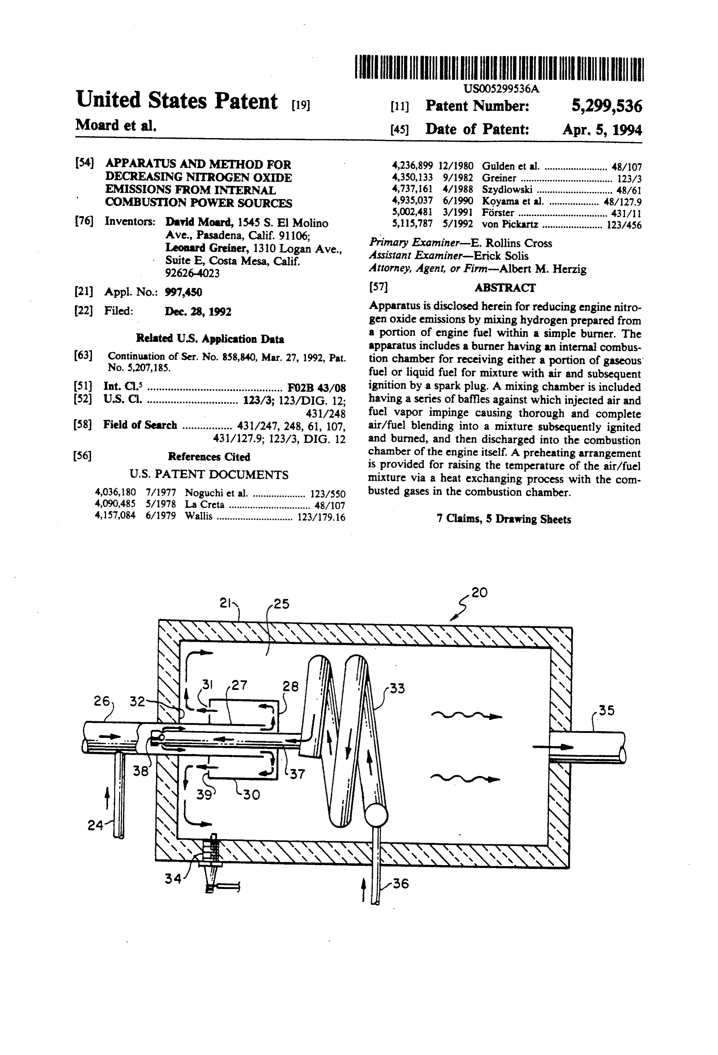
United States Patent (19) 11) Patent Number: 5,299,536 Moard et al. (45) Date of Patent: Apr. 5, 1994 (54) APPARATUS AND METHOD FOR 4,236,899 12/1980 Gulden et al. ........................ 48/107 DECREASING NROGEN OXOE 4,350,133 9/1982 Greiner ........... ... 123/3 EMESSIONS FROM INTERNAL 4,737,161 4/1988 Szydlowski............................. 48/61
COMBUST ON PO
WER SOURCES 4,935,037 6/1990 Koyama et al. 48/127.9 5,002,481 3/1991 Förster .................................. 431/1 76) Inventors: David Moard, 1545 S. El Molino 5,115,787 5/1992 von Pickartz ....................... 123/456 Ave., Pasadena, Calif. 91106; Primary Examiner-E. Rollins Cross
Leonard Greiner, 1310 Logan Ave., Assistant Examiner-Erick Solis
Suite E, Costa Mesa, Calif. Attorney, Agent, or Firm-Albert M. Herzig
No.: 997,450 57 it.
Apparatus is disclosed herein for reducing engine nitro 22 Filed: Dec. 28, 1992 gen oxide emissions by mixing hydrogen prepared from Related U.S.. . Application
Ap Data a portion of engine fuel within a simple burner. The apparatus includes a burner having an internal combus 63 Continuation of Ser. No. 858,840, Mar. 27, 1992, Pat. tion chamber for receiving either a portion of gaseous No. 5,207,185. fuel or liquid fuel for mixture with air and subsequent 51) int. Cl. .............................................. Fo2B 43/08 ignition by a spark plug. A mixing chamber is included 52 U.S. C. ............................... 123/3; 123/DIG. 12, having a series of baffles against which injected air and 431/248 fuel vapor impinge causing thorough and complete 58) Field of Search ................. 431/247, 248, 61, 107, air/fuel blending into a mixture subsequently ignited 431/127.9; 123/3, DIG. 12 and burned, and then discharged into the combustion chamber of the engine itself. A preheating arrangement (56) References Cited is provided for raising the temperature of the air/fuel
4,036,180 7/1977 Noguchi et al. .................... 123/550 busted gases in the combustion chamber. 4,090,485 5/1978 La Creta ..... a saw 48/107 4,157,084 6/1979 Wallis ............................. 123/179.16 7 Claims, 5 Drawing Sheets
Page 2
Drawing sheet — no readable text.
Page 3
Drawing sheet — no readable text.
Page 4
OOO
O.O O.5 O 5 2.O 2.5 3,O 3.5
STOICH RATO
FIG5 THERMAL DECOMPOST ON OF METHANE;
20 SPECIES FROM l CH4, AND ENERGY DATA
2OC 3OO 4OO SOO 6OO 7OO BOO 900 OOO
TEMP F
Page 5
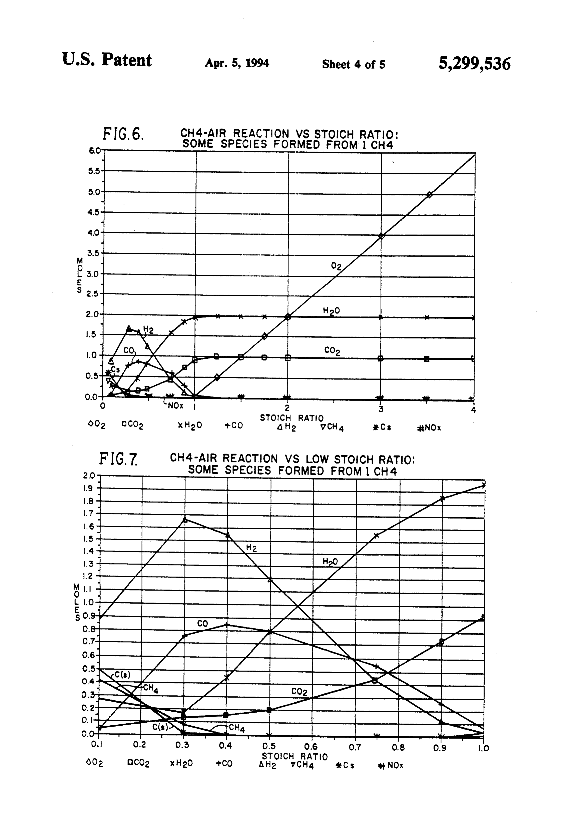
FIG.6 CH4-A R REACTION VS STOICH RATO:
s v. p. SOME SPECIES FORMED FROM CH4.
STOCH RATO
Q02 CO2 x H2O sCO A H2 wCH4 CS NOx
FIG.7 CH4 - AIR REACTION VS LOW STOCH RATO:
SOME SPECES FORMED FROM CH4.
ZNZ -1 Nin 4. CanS4CH4 S O. O.2 O.3 O.4 O.5 O.6 O.7 O,8 O.9 ..O
STOCH RATO
&O2 OCO2 x H2O --CO AH2 vCH4 Cs NOx
Page 6
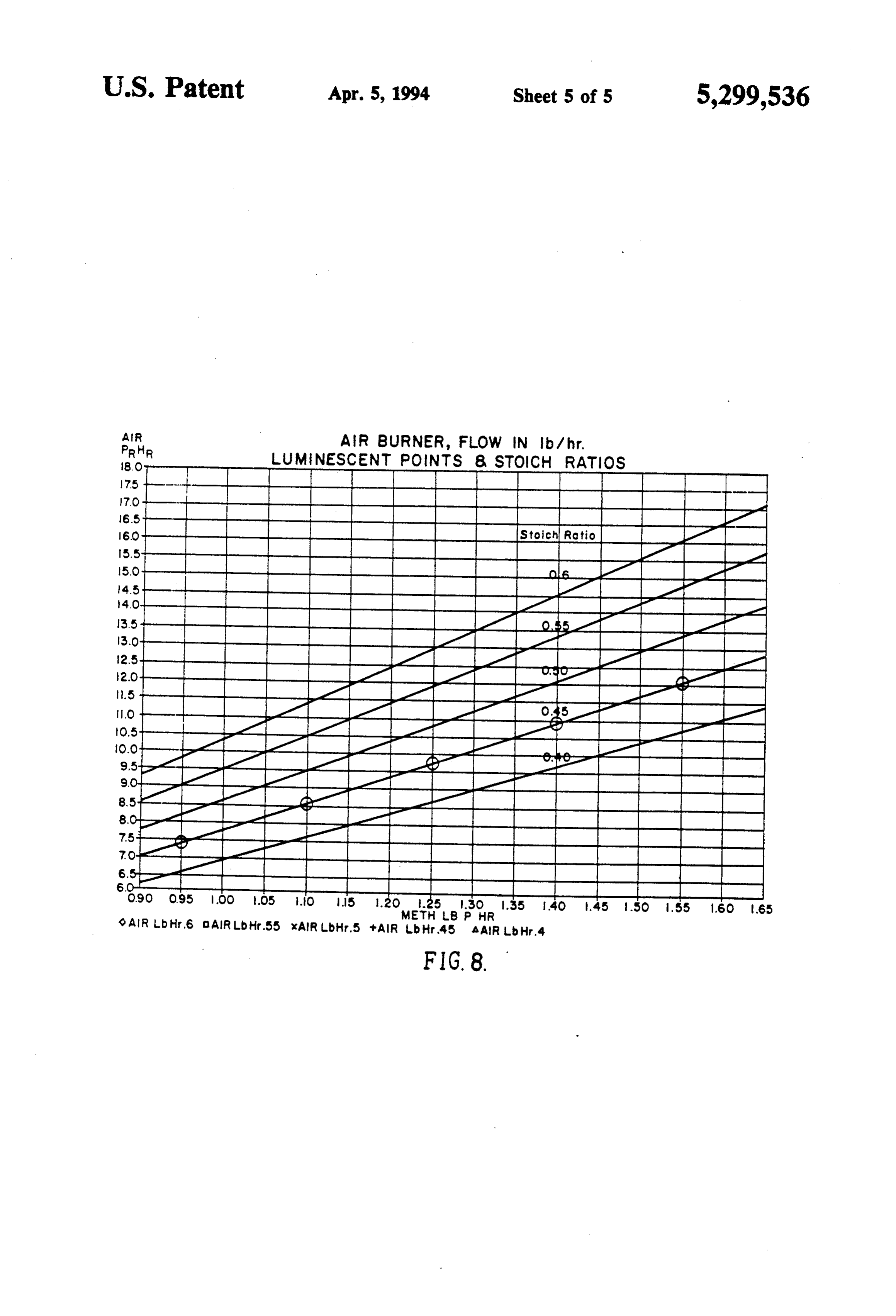
PRHR LUMNESCENT POINTS 8, STOCH RATIOS
selecti.
so 4-4 4 O
-4-4-2 | | | | | | | C ust g- || | | | | | | | LL - I I I I I I I I I I I I - LLL LI H O90 O.95 OO 105 i.O 15 .2O .25 .3O .35 4O .45 SO 55 6.O 65
METH B P HR
9 AR b Hr,6 O AllRLb. Hr.55 xAIR Lbir.5 + A R b Hr45 AAR Lb. Hr.4
Page 7
stored water or means to obtain it from the engine ex
APPARATUS AND METHOD FOR DECREASING haust, etc. In addition, it often is difficult to obtain rapid NTROGEN OXDE EMISSIONS FROM and accurate flow response Because of such factors, the NTERNAL COMBUSTON POWER SOURCES reformer process does not lend itself to an engine pro
5 CSSS.
This is a continuation of application Ser. No. The fuel may also be reacted with a deficiency of air O7,858,840 filed Mar. 27, 1992, now U.S. Pat. No. to produce hydrogen. Doing, so, however, is challeng 5,207,185. ing because the excess fuel is not highly reactive and BACKGROUND OF THE INVENTION therefore difficult to involve in the reaction. For this 10 reason, such previous processes relied on on catalysts 1. Field of the Invention and complex hardware, which tended to make the pro The present invention relates to the field of reducing cess virtually unusable. Thus, Houssman, etal, U.S. Pat. nitrogen oxide emission from internal combustion en No. 4,033,133 teaches the use of special high tempera gines and turbines, and more particularly to a novel ture catalyst coupled with intensive preheat of the reac means of adding hydrogen prepared by means of a 15 tants to combust fuel with air to produce hydrogen. novel burner from a portion or part of the main engine Such catalytic devices, by their nature, are complex, fuel whether it be gaseous or liquid. difficult to control, and require undesirably long start 2. Brief Description of the Prior Art up times. Thus, they do not lend themselves to an en It is well known that nitrogen oxides (NO) form at gine process.
the high temperatures normally associated with com 20 Therefore, a long-standing need has existed to pro-. bustion processes and that operating an engine at lean vide a novel apparatus and means for accomplishing a conditions with excess air lowers temperature and, technology breakthrough for a simple means of produc therefore, decreases NO. However, decades of engine ing hydrogen from fuel in a simple burner without the and turbine studies have shown that lean combustion catalyst or special pressurized hydrogen or related stor limits for all fuels are above those where NO emissions 25 age means normally considered. are below specified goals. Natural gas and gasoline are examples where lean combustion has been pushed to its SUMMARY OF THE INVENTION limit and where it has been found that hydrogen addi Accordingly, the above problems and difficulties are tion increases this limit to where NO output is accept obviated by the present invention which provides a ably low. However, means to obtain hydrogen for this 30 novel means and method utilizing a burner for combus purpose are beset with problems. tion air and hydrocarbons at fuel-rich stoichiometric Problems and difficulties have been encountered air/fuel ratios from 0.3 to 1, which includes a burner when the supply of hydrogen is provided by materials having a combustion chamber properly coupled to a carried in a separate tank which can be extremely heavy and requires pressurization. As examples, methanol, 35 amain source of fuel which includes means for diverting portion of the main fuel into the burner along with a hydrogen or ammonium nitrate can produce hydrogen portion of the main air so that the fuel portion and air when added to an engine combustor. portion impinge aqainst a first and second baffle ar However, these add to the fuel and so reduce the rangement whereby impingement thoroughly mixes the volumetric storage capacity which lowers overall per fuel/air combination preparatory for ignition in the formance, and results in complications through use of 40 combustion chamber. Ignition means are provided for secondary materials. Hydrogen stored in the pressur exhausting the burned gases from the burner into the ized container which holds methane (Hythane) can also combustion chamber of an engine. The excellent mixing be used, but this causes about 75 percent reduced engine provided by said impingements results in close to theo range for each percent hydrogen used because of its retical equilibration of the fuel-rich reaction, despite the very low energy content on a volumetric basis, and also 45 low reactivity of the excess fuel. requires special means to enable safe storage of hydro In one form of the invention, hydrogen gas is pro gen. duced by employing a portion of methane gas which is A more favorable method to obtain hydrogen is by mixed with the air by the baffle assembly, and in an properly treating a portion of the main engine fuel itself. other form of the invention, liquid fuel, such as gasoline, This does not require storing and using a new expend is vaporized in a heat exchanger in the burner combus able and can be accomplished with little or no loss of tor prior to mixture with air in the baffle assembly for fuel energy. Hydrogen may be produced from fuels by subsequent ignition and discharge to the engine com high-temperature decomposition, such as those listed in bustion compartment.
Greiner, U.S. Pat. No. 4,350,133. The actual patent The apparatus further includes a means for pre-heat discloses a fuel burner and decomposer combination on 55 ing the air/fuel mixture before combustion which is which hot gases produced from the burner heat a sec based on a heat exchange relationship with respect to ondary flow of fuel within a heat exchanger to tempera the fully combusted gases so that hydrogen output is tures where it decomposes to form hydrogen. It is in increased.
tended for use with methanol as fuel, which can Therefore, it is among the primary objects of the uniquely decompose without formation of solid carbon present invention to provide a novel burner apparatus "soot' which can harm the engine process. The burner for combusting air and hydrocarbons at fuel-rich stoi of the aforementioned patent cannot efficiently combust chiometric air/fuel ratios from 0.3 to 1 which incorpo when fuel rich, where otherwise hydrogen is produced. rates means to intimately mix the air and fuel vapors Hydrogen can also be produced by reacting the fuel prior to injection into a combustion chamber. with water to produce hydrogen through a "reform Another object of the present invention is to provide ing', process. Such a process, however, requires in a novel burner means having intimate premixing of fuel volved catalytic means to bring about the water-fuel and a deficiency of air which is achieved by bringing reaction, a heat input for its endothermic reaction, the air and fuel together in a separate chamber where
Page 8
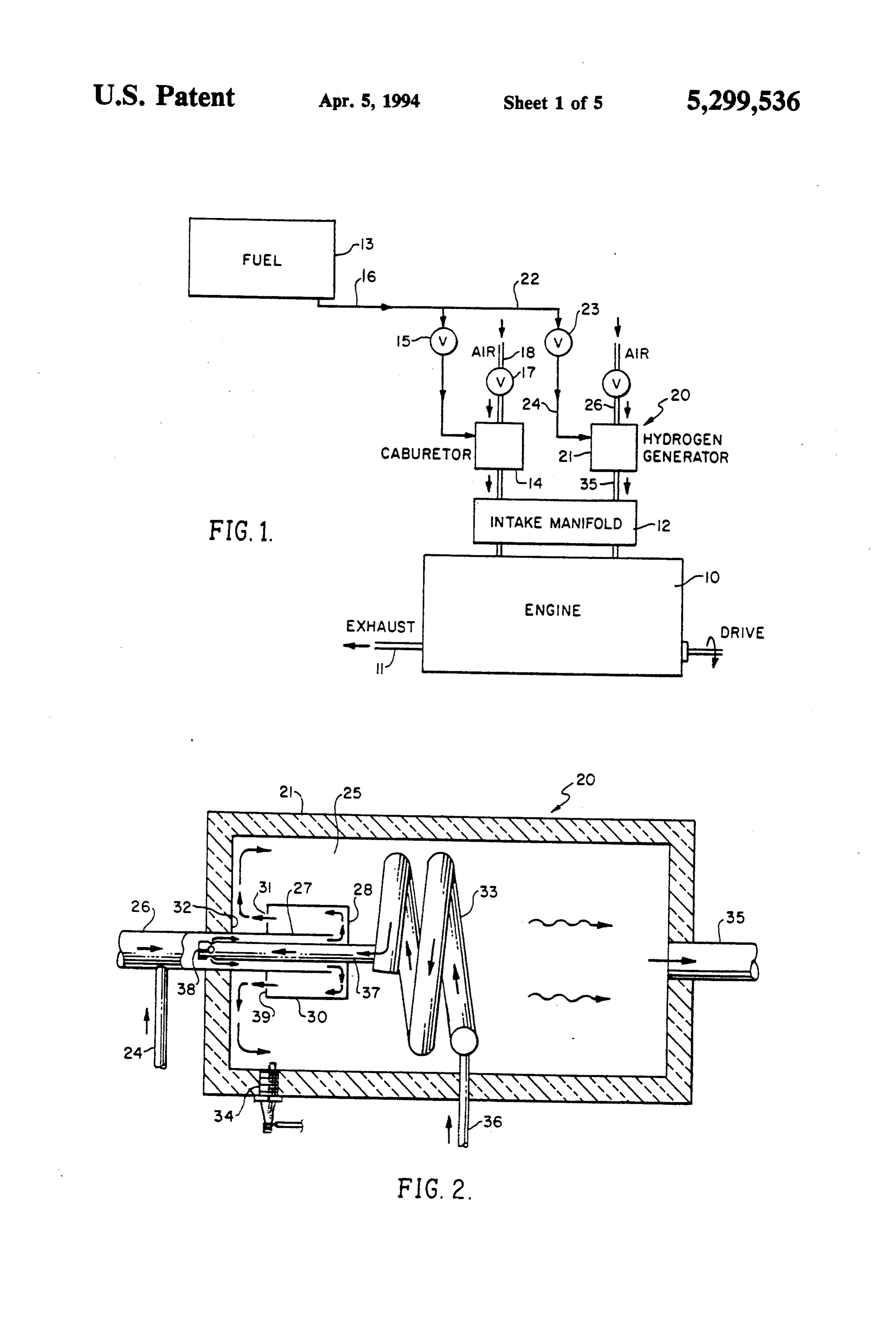
the flow is induced to move back and forth via a series FIG. 6 is a chart presenting further information on of baffle assemblies preparatory for entering the com major species at equilibrium versus air/fuel stoichiomet bustion chamber where ignition of the mixture occurs. ric ratio;
Another object of the present invention is to provide FIG. 7 is a chart which amplifies the section of FIG. a simple burner apparatus for converting a portion of 5 6 below a ratio of l; and main engine fuel to hydrogen which is then added to the FIG. 8 is a chart including experimental points for a main fuel flow to the engine so as to permit combustion methane-air burner where luminescent carbon appears. under conditions where little or reduced nitrogen oxide DESCRIPTION OF THE PREFERRED is produced. EMBODIMENT
Yet another object is to provide a novel burner appa 10 ratus which is a very simple, non-catalytic burner means Referring to FIG. 1, a schematic illustration is pres to produce hydrogen from a portion of the main engine ented wherein numeral 10 represents a conventional fuel for injection into the main engine combustor with combustion engine having an exhaust 11 which nor mally emits gases having a high level of nitrogen oxide, the remainder of the fuel to attain high air/fuel ratios 15 as well as other contaminants. However, by employ leading to minimal nitrogen oxide formation.
Still a further object of the present invention is to ment of the present invention, these contaminants are provide a hydrogen generator for use in connection greatly reduced or eliminated. The engine 10 includes a with reducing nitrogen oxide in an engine emission 13 manifold 12 into which engine fuel from a storage tank which does not require additives that degrade fuel per 20 ber. is introduced to the engine main combustion cham formance and which burner contributes little to engine ducedThe fuel contained within tank 13 is mainly intro to the manifold 12 through a carburetor 14 via a complexity.
Yet another object of the present invention is to pro Ambientregulating valve 15 connected to a main fuel line 16. air is introduced to the carburetor for mixture vide a novel means and apparatus to reduce nitrogen with the main oxides from internal combustion engines and turbines 25 18. Thus, it canfuel supply via a valve 17 and an air inlet be seen that the combustion engine 10 is by utilization of a simple hydrogen generator fed by a employed small portion of main engine fuel whereby the resultant wherein thewith main fuel from tank 13 via the carburetor 14 fuel supply is mixed with air accord hydrogen produced is to be co-fired in the engine with ing to a proper ratio to permit efficient combustion in the remainder of the main fuel. the engine 10.
A further object resides in the provision of an air/fuel 30 However, the conventional system described is en mixture pre-heating means so as to provide a higher hanced by utilization of the novel burner apparatus of combustion temperature to assist the equilibration pro the present invention, indicated in the general direction CeSS. of arrow 20 which may be referred to as a hydrogen Another object resides in employment of a pre-heat generator for supplying a hydrogen vapor to the mani ing means to insure vaporization of liquid fuel with 35 fold 12 in order to reduce or eliminate nitrogen oxide in increased hydrogen output. the combustion engine exhaust. Still further, the hydrogen generator employs a pre It can be seen in FIG. 1 that the hydrogen generator, heater means utilizing heat exchanger processing of indicated by numeral 21, is supplied with a portion of combusted gases to increase the temperature of the the main fuel supply by means of a bypass line con air/fuel mixture. 40 nected to main line 16, and which is coupled to the
BRIEF DESCRIPTION OF THE DRAWINGS
hydrogen generator 21 through a valve 23. Line 24 connects the valve 23 with the generator 21.
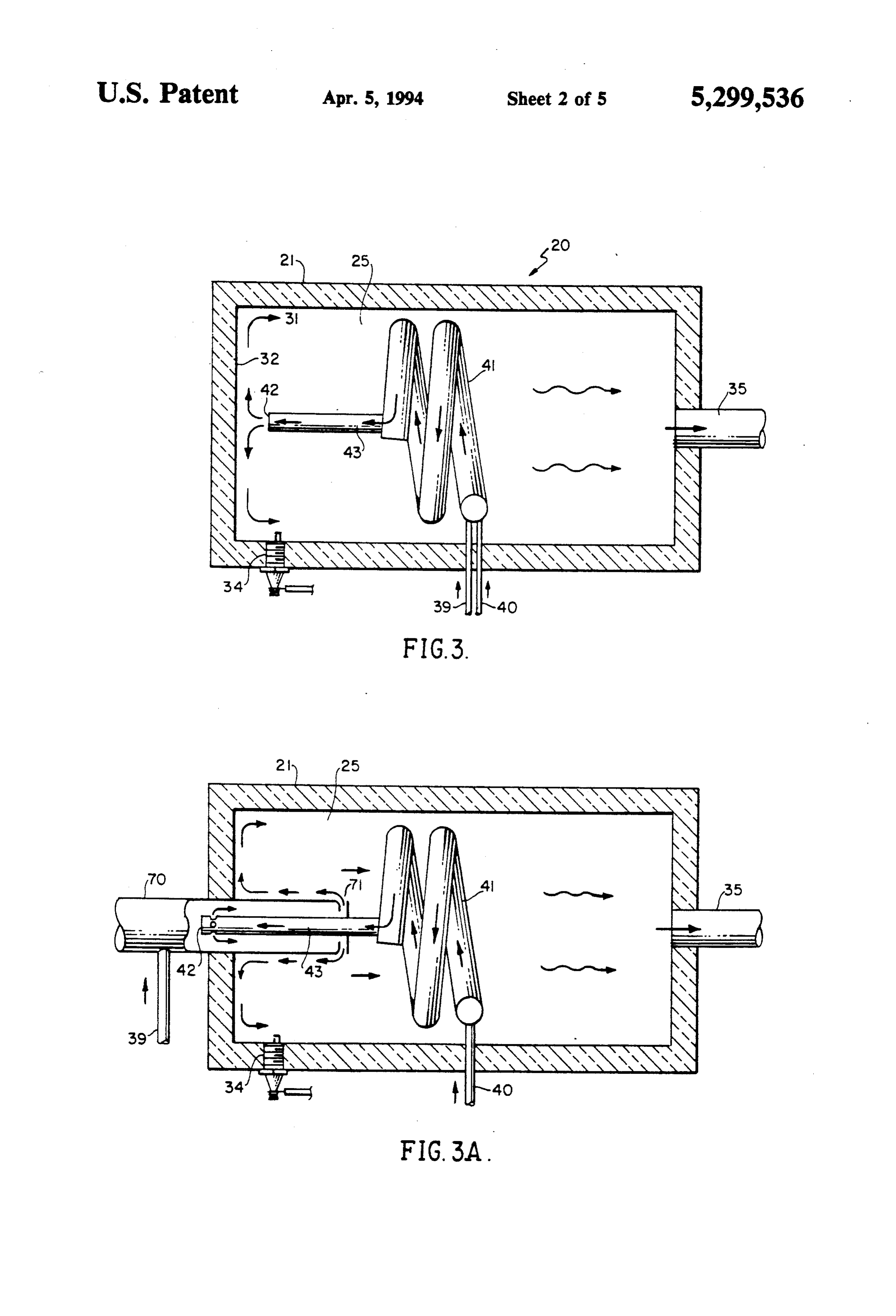
The features of the present invention which are be Referring now in detail to FIG. 2, the hydrogen gen lieved to be novel are set forth with particularity in the erator 21 includes a housing having an internal combus appended claims. The present invention, both as to its tion chamber 25 in which the hydrogen generating organization and manner of operation, together with means are located. When the main fuel is a gas, such as further objects and advantages thereof, may best be methane, a portion of the gas is introduced via line 24 in understood with reference to the following description, combination with air supplied via line 26 so that the taken in connection with the accompanying drawings in 50 gas/air is initially combined in a tube 27 within the which: combustion chamber 25. The tube 27 is open-ended so FIG. 1 is a schematic drawing of a combustion engine that the combined gas/air is directed towards a baffle 28 incorporating the novel hydrogen generation means of carried on the end of a cup 30. The combined gas/air the present invention effective to reduce nitrogen oxide impinges against the baffle 28, as indicated by the flow in the engine emissions; of arrows such that the flow is reversed upon itself and FIG. 2 is an enlarged diagrammatic view in section 55 exits through the open end of the cup 30, indicated by numeral 31. The two streams of air and gas move to illustrating the novel burner means employed in the gether through engine system shown in FIG. 1 for hydrogen genera cup 30 where thethestreams tube 27 so as to finally exit inside the impinge on the baffle 28. This tion; causes flow direction changes, first 90 degrees radially F10S. 3 and 3A are diagrammatic sectional views of 60 outward and then 90 degrees to the opening 31. This the hidden generator employing a pre-heater means process induces mixture of the air and gas. The reversed using heat exchange principles;
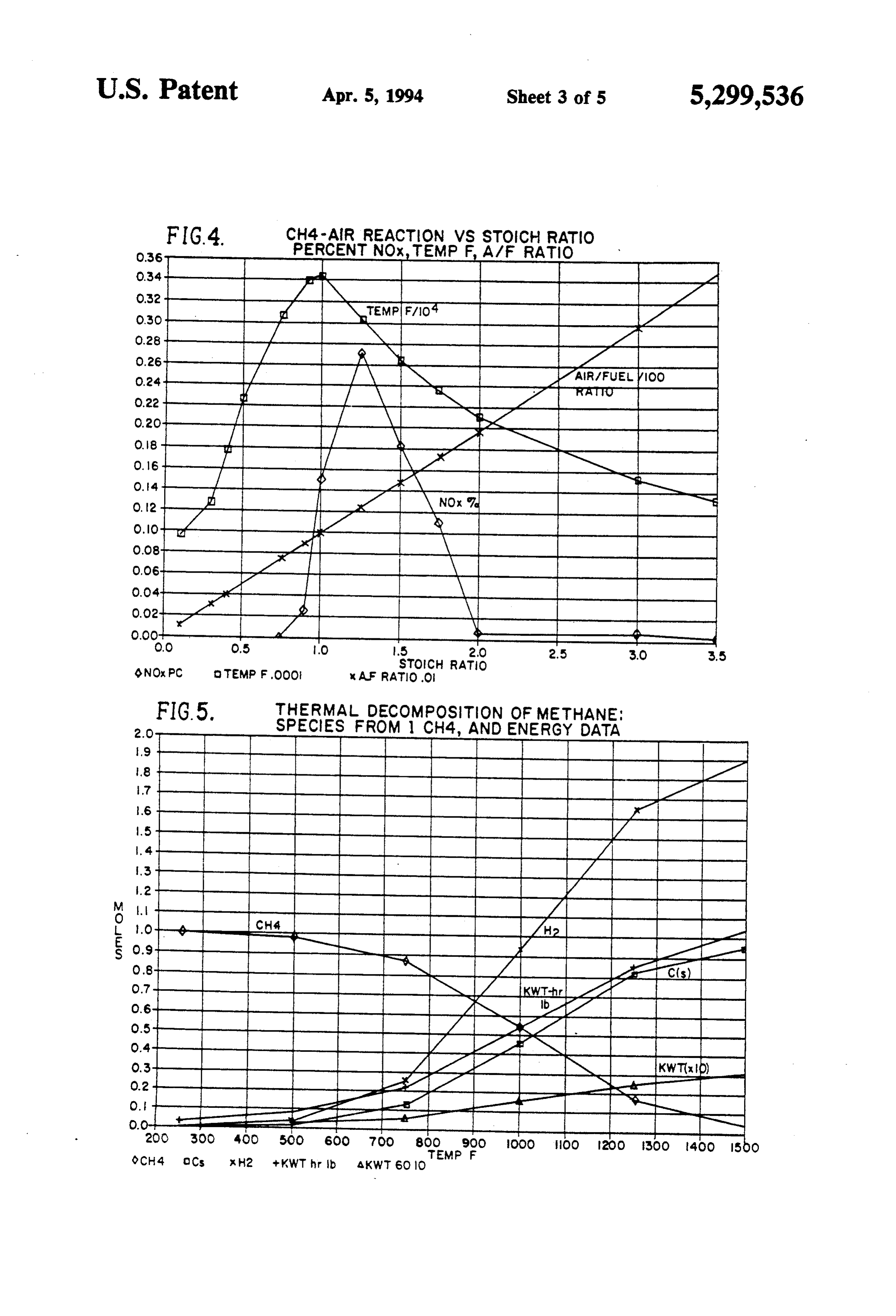
FIG. 4 is a chart pertaining to factors contributing to diately impinges onat the flow exits the cup orifice or opening 31 and imme the end of the burn wall, indicated nitrogen oxide formation involving reaction between by numeral 32, serving as a second baffle where the methane (CH4) and air (O2-4N2); 65 flow is again abruptly caused to move at successive FIG. 5 is a chart similar to the chart of FIG. 4 involve right angles producing further mixing. The thoroughly ing the decomposition of methane at various tempera mixed gas and air is now within the combustion cham tures based on equilibrium species per mole of methane; ber 25 wherein ignition of the mixed gases by gases
Page 9
already burning in the burner combustion chamber curve towards the end wall. This curve is known as a takes place. The initial ignition of the first entry of unig "Coanda' curve. The combination causes the flow to nited gases occurs upon operation of a spark plug 34 bend over and follow down the outside of the attached having its electrodes within the combustion chamber tube. The Coanda device is used to induct air from the 25. The flame continues through the burner and finally surroundings into the lamina made by a smaller flow of exits at a discharge duct 35 from which it is introduced air pumped into the Coanda. Up to 100 times the air to the combustion chamber of the engine 10. flow can be so educted. Using this in the burner will In another instance, when the main fuel is a liquid, cause circulation of the burning gases, which decreases Such as gasoline, the fuel is introduced through a line the length of the combustion chamber. and moves through the heat exchanger coils 33. Heat 10 The inventive from the burning gases is properly exchanged to the excess-fuel burnersconcept is shows that equilibration in achieved if the air and fuel are liquid fuel causing it to vaporize. The latter vaporized very homogeneously mixed prior gases then pass through a tube 37 eventually being con ently, within this intimate mixture, toheat ignition. Appar supplied from ducted through openings, such as opening 38, where the oxidation of part of the fuel is simultaneously gases meet oncoming air in the line 26 with resultant 15 by unreacted fuel in immediate contact, whichabsorbed then do consequences as described immediately above. decompose to equilibrium products. Referring now in detail to FIG. 3, a fuel pre-heating arrangement is illustrated. The hydrogen generator 20 airThis intimate premixing is achieved by bringing the includes a housing 21 having an internal combustion flow is fuel and together in a separate chamber, where the chamber 25 in which the hydrogen generator means are 20 mixture made to move back and forth. This intimate located. The main fuel, liquid orgas, is introduced in the ignition occurs. It isthe then enters combustion chamber wherein necessary that burning does not combustion chamber 25 via an input fuel line 39 so that the gas/air mixture is initially combined in spiral tube travel back into the mixing chamber, despite the burn 41. Tube 41 is in heat exchange relationship with the hot ing gases at their exit, which normally is an excellent gases 31 formed in the chamber 25 after combustion has 25 ignition source.
taken place. The tube is of sufficient length so that the This is prevented by the velocity of the stream that internal air/fuel mixture is heated within the range of that thetheratemixing leaves chamber, taking advantage of the fact of burning through a mixture of fuel and air 500" to 1000' F., which insures vaporization of the liquid fuel. The length of tubing required for such heat occurs at a finite rate. Thus, if the burning rate is 1 ing effects virtually completes thorough mixing of the ft./sec., then the gas mixture exiting the mixing cham air/fuel mixture in the tube 41. A tube 43 is attached to ber must travel at a higher rate. Otherwise, the burning tube 41 having an open end 42 located in close proxim gases in the burner would cause a burning lamina to ity to the insulated housing end plate 32. The pre-heated travel back into the mixing chamber, which would be and pre-mixed mixture impinges upon end plate 32 and destructive.
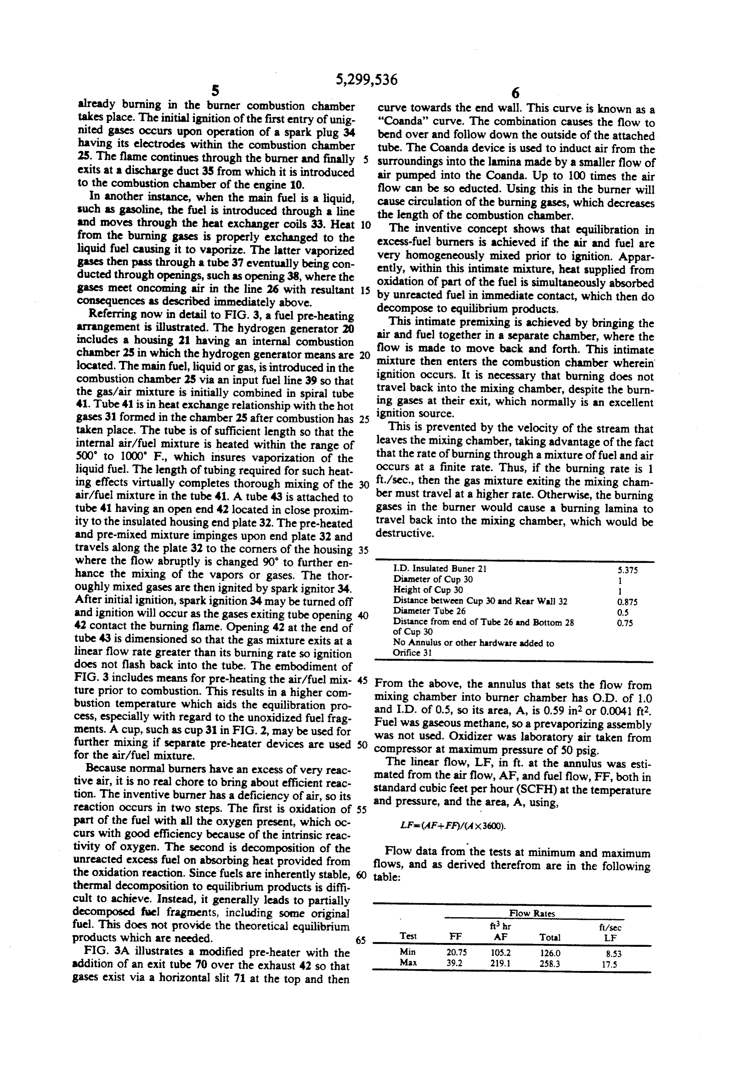
travels along the plate 32 to the corners of the housing 35 where the flow abruptly is changed 90' to further en I.D. insulated Buner 21 5.375 hance the mixing of the vapors or gases. The thor Diameter of Cup 30 1. oughly mixed gases are then ignited by spark ignitor 34. Height of Cup 30
After initial ignition, spark ignition 34 may be turned off Distance between Cup 30 and Rear Wall 32 0.87s and ignition will occur as the gases exiting tube opening 40 Diameter Tube 26 0.5 Distance from end of Tube 26 and Bottorn 28 0.75 42 contact the burning flame. Opening 42 at the end of of Cup 30 tube 43 is dimensioned so that the gas mixture exits at a No Annulus or other hardware added to linear flow rate greater than its burning rate so ignition Orifice 31 does not flash back into the tube. The embodiment of
FIG. 3 includes means for pre-heating the air/fuel mix 45 From the above, the annulus that sets the flow from ture prior to combustion. This results in a higher com mixing bustion temperature which aids the equilibration pro and I.D.chamber into burner chamber has O.D. of 1.0 cess, especially with regard to the unoxidized fuel frag Fuel was of 0.5, so its area, A, is 0.59 in? or 0.0041 ft2. gaseous methane, so a prevaporizing assembly ments. A cup, such as cup 31 in FIG. 2, may be used for was not used. Oxidizer was laboratory air taken from further mixing if separate pre-heater devices are used compressor at maximum pressure of 50 psig. for the air/fuel mixture.
Because normal burners have an excess of very reac mated The linear flow, LF, in ft. at the annulus was esti tive air, it is no real chore to bring about efficient reac standardfrom the airflow, AF, and fuel flow, FF, both in cubic feet per hour (SCFH) at the temperature tion. The inventive burner has a deficiency of air, so its and pressure, and the area, A, using, reaction occurs in two steps. The first is oxidation of 55 part of the fuel with all the oxygen present, which oc LFs (AF-FF)/(Ax3600).
curs with good efficiency because of the intrinsic reac tivity of oxygen. The second is decomposition of the Flow data from the tests at minimum and maximum unreacted excess fuel on absorbing heat provided from flows, and as derived therefrom are in the following the oxidation reaction. Since fuels are inherently stable, table:
thermal decomposition to equilibrium products is diffi cult to achieve. Instead, it generally leads to partially decomposed fuel fragments, including some original Flow Rates fuel. This does not provide the theoretical equilibrium fishr ft/sec products which are needed. 65 Test FF AF Total F FIG. 3A illustrates a modified pre-heater with the Min 20.75 105.2 126.0 8.53 addition of an exit tube 70 over the exhaust 42 so that Max 39.2 219. 258.3 17.5 gases exist via a horizontal slit 71 at the top and then
Page 10
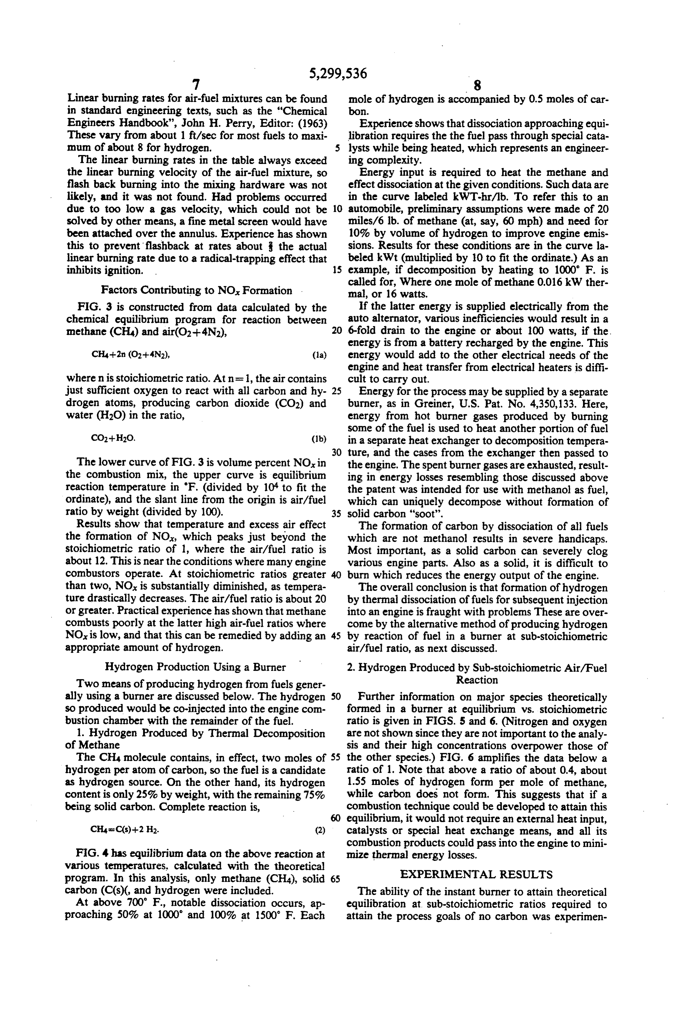
Linear burning rates for air-fuel mixtures can be found mole of hydrogen is accompanied by 0.5 moles of car in standard engineering texts, such as the "Chemical bon.
Engineers Handbook", John H. Perry, Editor: (1963) Experience shows that dissociation approaching equi These vary from about 1 ft/sec for most fuels to maxi libration requires the the fuel pass through special cata mum of about 8 for hydrogen. 5 lysts while being heated, which represents an engineer The linear burning rates in the table always exceed ing complexity.
the linear burning velocity of the air-fuel mixture, so Energy input is required to heat the methane and flash back burning into the mixing hardware was not effect dissociation at the given conditions. Such data are likely, and it was not found. Had problems occurred in the curve labeled kWT-hr/lb. To refer this to an due to too low a gas velocity, which could not be 10 automobile, preliminary assumptions were made of 20 solved by other means, a fine metal screen would have miles/6 lb. of methane (at, say, 60 mph) and need for been attached over the annulus. Experience has shown 10% by volume of hydrogen to improve engine emis this to prevent flashback at rates about the actual sions. Results for these conditions are in the curve la linear burning rate due to a radical-trapping effect that beled kWt (multiplied by 10 to fit the ordinate.) As an inhibits ignition. 15 example, if decomposition by heating to 1000 F. is called for, Where one mole of methane 0.016 kW ther
Factors Contributing to NO, Formation mal, or 16 watts.
FIG. 3 is constructed from data calculated by the If the latter energy is supplied electrically from the chemical equilibrium program for reaction between auto alternator, various inefficiencies would result in a methane (CH4) and air(O2-4N2), 20 6-fold drain to the engine or about 100 watts, if the. energy is from a battery recharged by the engine. This
CH4+2n (O2-4N2), (a) energy would add to the other electrical needs of the engine and heat transfer from electrical heaters is diffi where n is stoichiometric ratio. At n = 1, the air contains cult to carry out.
just sufficient oxygen to react with all carbon and hy 25 Energy for the process may be supplied by a separate drogen atoms, producing carbon dioxide (CO2) and burner, as in Greiner, U.S. Pat. No. 4,350,133. Here, water (H2O) in the ratio, energy from hot burner gases produced by burning some of the fuel is used to heat another portion of fuel
CO2-H2O. (1b) in a separate heat exchanger to decomposition tempera 30 ture, and the cases from the exchanger then passed to
The lower curve of FIG. 3 is volume percent NO, in the engine. The spent burner gases are exhausted, result the combustion mix, the upper curve is equilibrium ing in energy losses resembling those discussed above reaction temperature in "F. (divided by 10 to fit the the patent was intended for use with methanol as fuel, ordinate), and the slant line from the origin is air/fuel which can uniquely decompose without formation of ratio by weight (divided by 100). 35 solid carbon "soot'.
Results show that temperature and excess air effect The formation of carbon by dissociation of all fuels the formation of NO, which peaks just beyond the which are not methanol results in severe handicaps. stoichiometric ratio of 1, where the air/fuel ratio is Most important, as a solid carbon can severely clog about 12. This is near the conditions where many engine various engine parts. Also as a solid, it is difficult to combustors operate. At stoichiometric ratios greater burn which reduces the energy output of the engine. than two, NOx is substantially diminished, as tempera The overall conclusion is that formation of hydrogen ture drastically decreases. The air/fuel ratio is about 20 by thermal dissociation of fuels for subsequent injection or greater. Practical experience has shown that methane into an engine is fraught with problems These are over combusts poorly at the latter high air-fuel ratios where come by the alternative method of producing hydrogen NOx is low, and that this can be remedied by adding an 45 by reaction of fuel in a burner at sub-stoichiometric appropriate amount of hydrogen. air/fuel ratio, as next discussed. Hydrogen Production Using a Burner 2. Hydrogen Produced by Sub-stoichiometric Air/Fuel Two means of producing hydrogen from fuels gener Reaction ally using a burner are discussed below. The hydrogen 50 Further information on major species theoretically so produced would be co-injected into the engine com formed in a burner at equilibrium vs. stoichiometric bustion chamber with the remainder of the fuel. ratio is given in FIGS. 5 and 6. (Nitrogen and oxygen 1. Hydrogen Produced by Thermal Decomposition are not shown since they are not important to the analy of Methane sis and their high concentrations overpower those of The CH4 molecule contains, in effect, two moles of 55 the other species.) FIG. 6 amplifies the data below a hydrogen per atom of carbon, so the fuel is a candidate ratio of 1. Note that above a ratio of about 0.4, about as hydrogen source. On the other hand, its hydrogen 1.55 moles of hydrogen form per mole of methane, content is only 25% by weight, with the remaining 75% while carbon does not form. This suggests that if a being solid carbon. Complete reaction is, combustion technique could be developed to attain this equilibrium, it would not require an external heat input,
CH4 eC(s)--2 H2. (2) catalysts or special heat exchange means, and all its combustion products could pass into the engine to mini
FIG. 4 has equilibrium data on the above reaction at mize thermal energy losses.
various temperatures, calculated with the theoretical EXPERMENTAL RESULTS program. In this analysis, only methane (CH4), solid 65 carbon (CCs)(, and hydrogen were included. The ability of the instant burner to attain theoretical At above 700 F., notable dissociation occurs, ap equilibration at sub-stoichiometric ratios required to proaching 50% at 1000' and 100% at 1500 F. Each attain the process goals of no carbon was experimen
Page 11
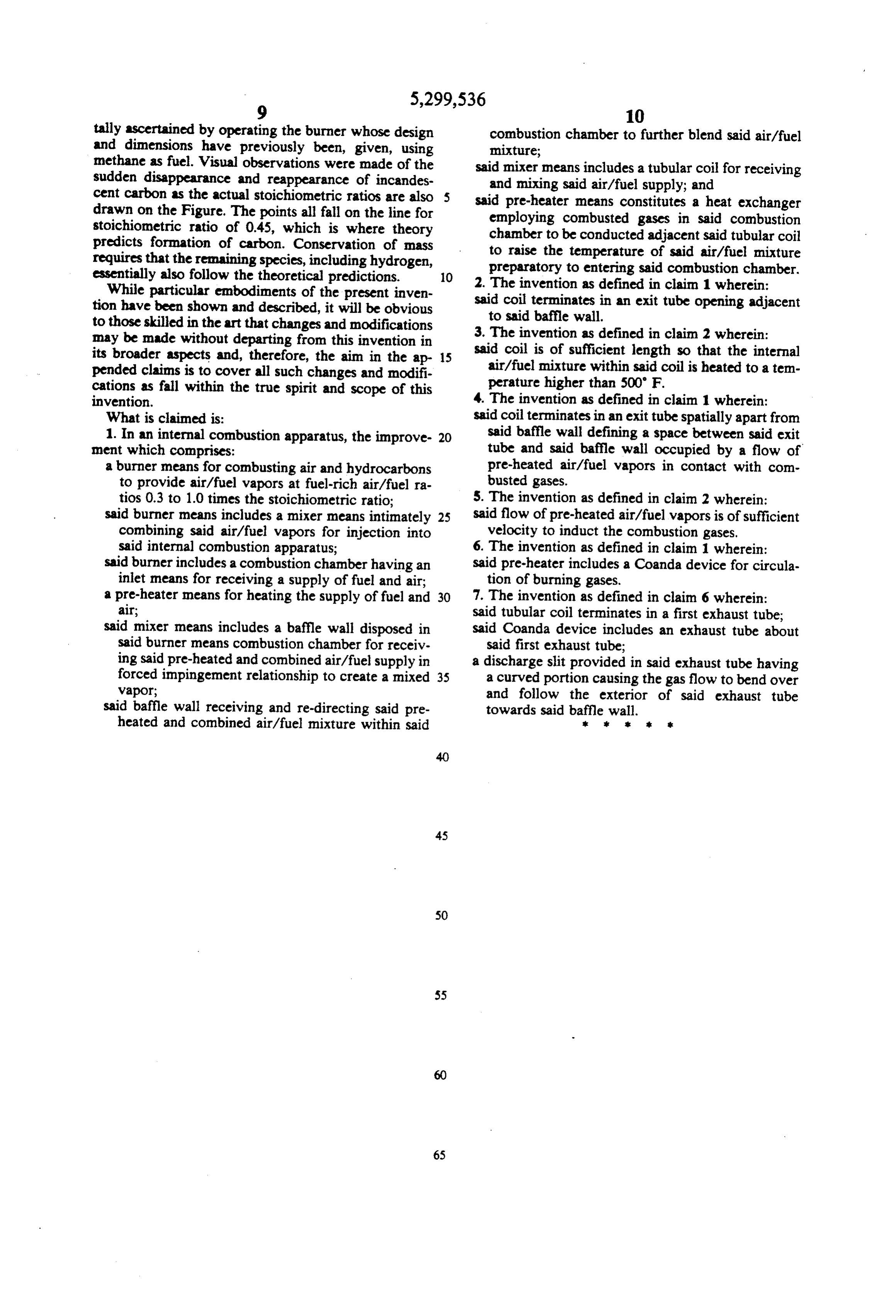
tally ascertained by operating the burner whose design combustion chamber to further blend said air/fuel and dimensions have previously been, given, using mixture;
methane as fuel. Visual observations were made of the said mixer means includes a tubular coil for receiving sudden disappearance and reappearance of incandes and mixing said air/fuel supply; and cent carbon as the actual stoichiometric ratios are also said pre-heater means constitutes a heat exchanger drawn on the Figure. The points all fall on the line for employing combusted gases in said combustion stoichiometric ratio of 0.45, which is where theory chamber to be conducted adjacent said tubular coil predicts formation of carbon. Conservation of mass to raise the temperature of said air/fuel mixture requires that the remaining species, including hydrogen, preparatory to entering said combustion chamber. essentially also follow the theoretical predictions. 2. The invention as defined in claim 1 wherein: While particular embodiments of the present inven said coil terminates in an exit tube opening adjacent tion have been shown and described, it will be obvious to said baffle wall.
to those skilled in the art that changes and modifications 3. The invention as defined in claim 2 wherein: may be made without departing from this invention in its broader aspects and, therefore, the aim in the ap 15 said coil is of sufficient length so that the internal pended claims is to cover all such changes and modifi air/fuel mixture within said coil is heated to a tem cations as fall within the true spirit and scope of this perature higher than 500' F. invention. 4. The invention as defined in claim 1 wherein: What is claimed is: said coil terminates in an exit tube spatially apart from 1. In an internal combustion apparatus, the improve 20 said baffle wall defining a space between said exit ment which comprises: tube and said baffle wall occupied by a flow of a burner means for combusting air and hydrocarbons pre-heated air/fuel vapors in contact with com to provide air/fuel vapors at fuel-rich air/fuel ra busted gases.
tios 0.3 to 1.0 times the stoichiometric ratio; 5. The invention as defined in claim 2 wherein: said burner means includes a mixer means intimately 25 said flow of pre-heated air/fuel vapors is of sufficient combining said air/fuel vapors for injection into velocity to induct the combustion gases. said internal combustion apparatus; 6. The invention as defined in claim 1 wherein: said burner includes a combustion chamber having an said pre-heater includes a Coanda device for circula inlet means for receiving a supply of fuel and air; tion of burning gases.
a pre-heater means for heating the supply of fuel and 30 7. The invention as defined in claim 6 wherein: alr; said tubular coil terminates in a first exhaust tube; said mixer means includes a baffle wall disposed in said Coanda device includes an exhaust tube about said burner means combustion chamber for receiv said first exhaust tube;
ing said pre-heated and combined air/fuel supply in a discharge slit provided in said exhaust tube having forced impingement relationship to create a mixed 35 a curved portion causing the gas flow to bend over vapor; and follow the exterior of said exhaust tube said baffle wall receiving and re-directing said pre towards said baffle wall. heated and combined air/fuel mixture within said r k ax sk
Provenance
- Collection
- Cited prior art
- Original PDF
- patentimages.storage.googleapis.com →
- Filed
- 1992-12-28
- Pages
- 11
- Method
- pdftotext (the PDF's own text layer) + pdftoppm 300dpi page scans
- Source
- Google Patents bibliographic record
- Granted
- 1994-04-05
- Inventors
- David Moard; Leonard Greiner
- Transcribed from
- patentimages.storage.googleapis.com →