patent · US3901197
Method and device for reforming the quality of fuel oil in an internal combustion engine
26 August 1975
Page 1 — bibliographic record
United States Patent (19) 11 3,901,197 Noguchi et al. (45) Aug. 26, 1975 54 METHOD AND DEVICE FOR REFORMING 3,688,755 9/1972 Grayson et al.......................... 123/3 THE QUALITY OF FUEL OIL IN AN 3,828,736 8/1974 Koch................................... 12311 A INTERNAL COMBUSTION ENGINE OTHER PUBLICATIONS 75) Inventors: Masaaki Noguchi, Nagoya, Carburetor with Spark Plug; a New Development for Masaharu Sumiyoshi, Toyota, both Vaporizing Kerosene, Scientific American, Nov. 17, of Japan 1917, pp. 368.
73 Assignee: Toyota Jidosha Kogyo Kabushiki
Kaisha, Japan Primary Examiner-Charles J. Myhre
Assistant Examiner-James D. Liles (22) Filed: May 1, 1974 Attorney, Agent, or Firm-Oblon, Fisher, Spivak, 21 Appl. No.: 466,028 McClelland & Maier
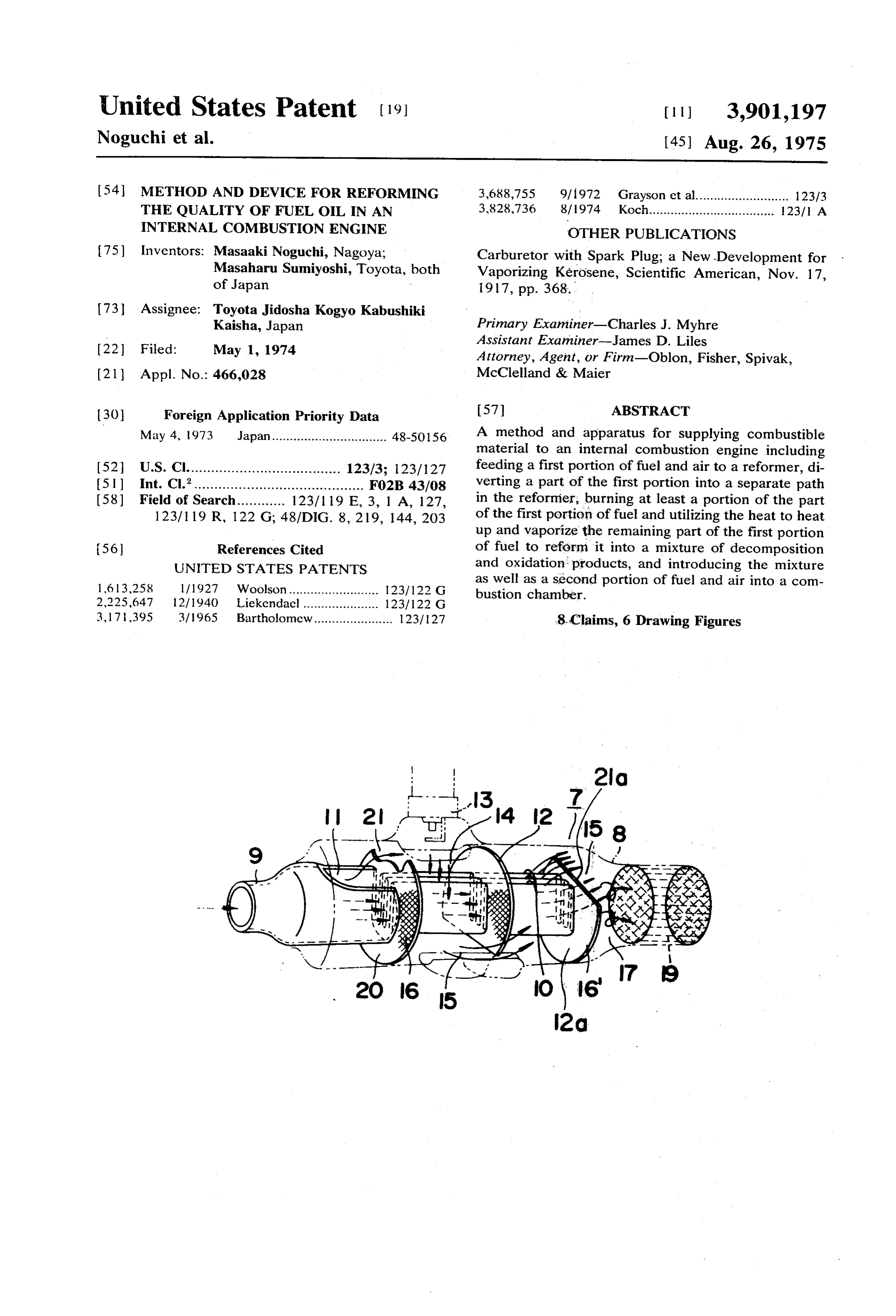
30 Foreign Application Priority Data 57 ABSTRACT May 4, 1973 Japan................................ 48-5O156 A method and apparatus for supplying combustible material to an internal combustion engine including 52 U.S. Cl...................................... 123/3; 123/127 feeding a first portion of fuel and air to a reformer, di (5) Int. Cl.’.......................................... F02B 43/08 verting a part of the first portion into a separate path (58) Field of Search............ 123/119 E, 3, 1 A, 127, in the reformer, burning at least a portion of the part 123/ 19 R, 122 G; 48/DIG. 8, 219, 144, 203 of the first portion of fuel and utilizing the heat to heat up and vaporize the remaining part of the first portion 56) References Cited of fuel to reform it into a mixture of decomposition UNITED STATES PATENTS and oxidation products, and introducing the mixture 16 13,258 l/1927 Woolson......................... 123/122 G as well as a second portion of fuel and air into a com bustion chamber.
2,225,647 12/1940 Liekendael..................... 123/122 G 3,171,395 3/1965 Bartholomew...................... 123/127 8. Claims, 6 Drawing Figures
Page 2
Drawing sheet — no readable text.
Page 3
Drawing sheet — no readable text.
Page 4
Drawing sheet — no readable text.
Page 5
METHOD AND DEVICE FOR REFORMING THE it is ignited and burned, heating and vaporizing the mix QUALITY OF FUEL OIL IN AN INTERNAL ture flowing in the first path by the heat of the burned COMBUSTON ENGINE mixture in the second path, and then sending a blend CROSS-REFERENCE TO RELATED of the fuel gases in both paths and air to a catalyzer. APPLICATIONS BRIEF DESCRIPTION OF THE DRAWINGS
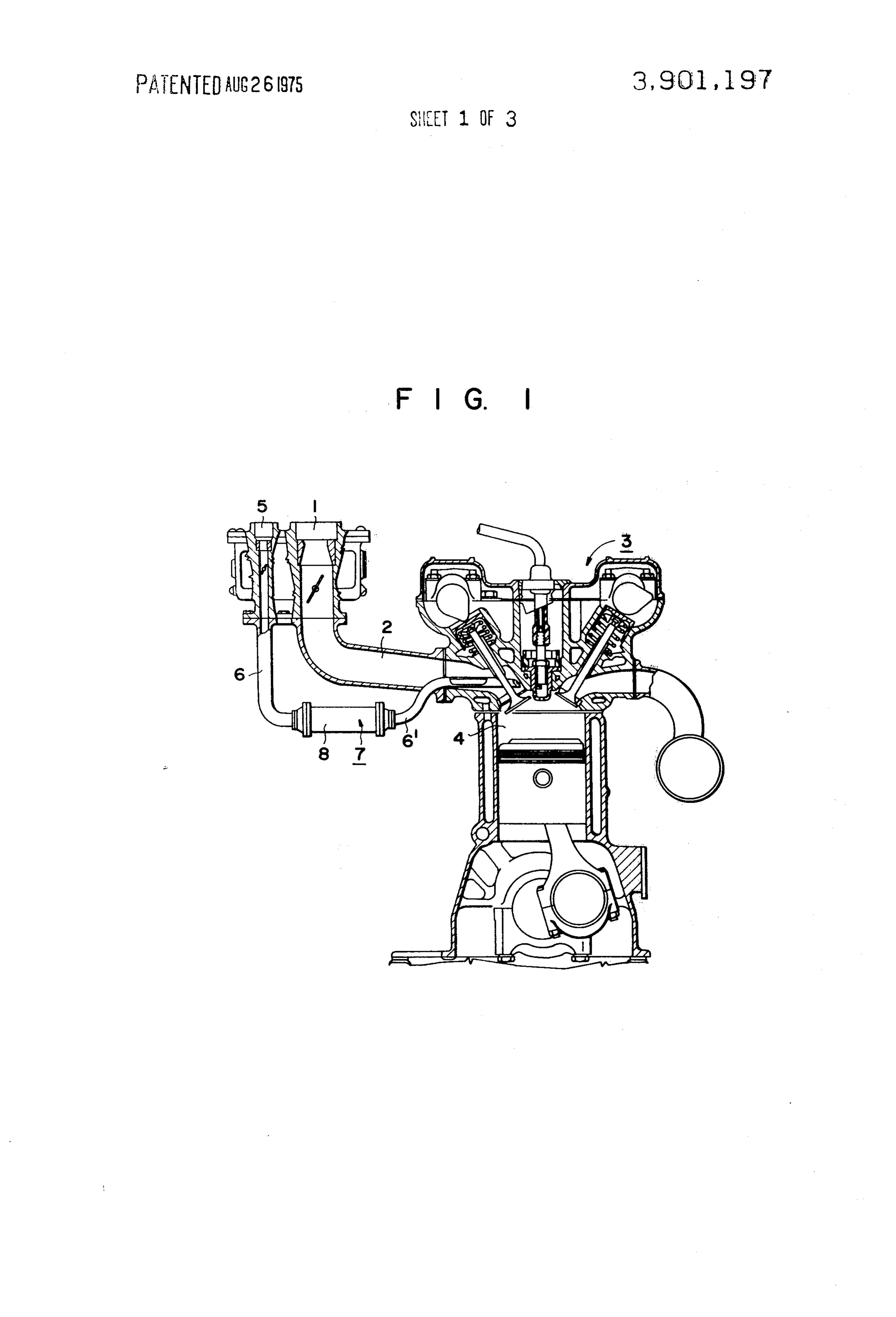
This application is an improvement of U.S. Pat. appli Various other objects, features and attendant advan cation Ser. No. 430,650 filed Jan. 4, 1974, for “IN tages of the present invention will be more fully appre TERNAL COMBUSTION ENGINE’ which was in ciated as the same becomes better understood from the vented by the applicants of this improved application O following detailed description when considered in con and others, said applications being commonly owned nection with the accompanying drawings, wherein like by the same assignee. reference characters designate like or corresponding BACKGROUND OF THE INVENTION parts throughout the several views, and in which: FIG. 1 is a schematic diagram showing a longitudinal
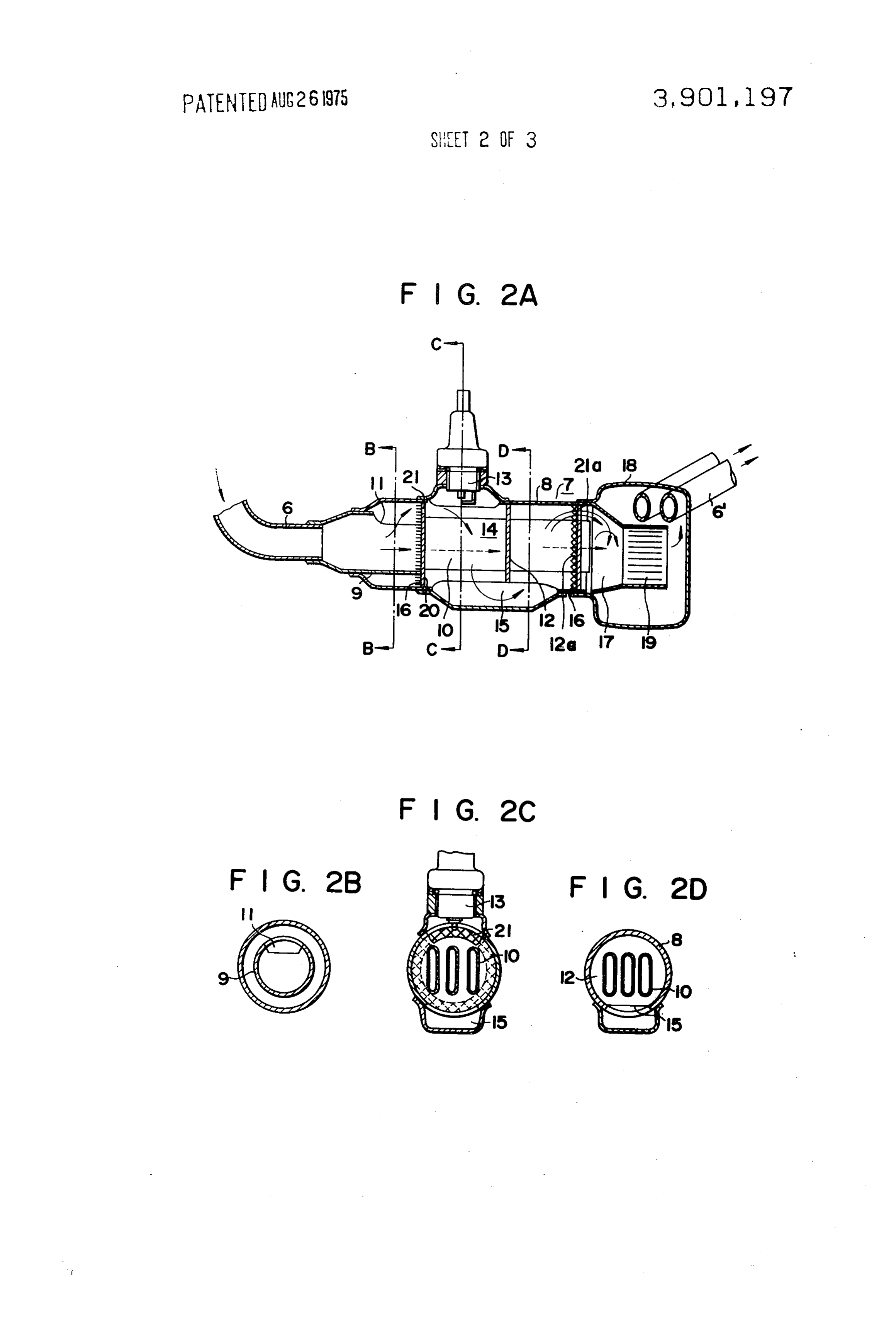
The present invention relates generally to internal 15 section of an internal combustion engine equipped with combustion engines and the supplying of fuel thereto, the embodiment of the present invention; and more particularly to a method and a device for re FIG. 2A is an enlarged longitudinal sectional view of forming the quality of hydrocarbon fuel oil to be sup the embodiment of the present invention shown in FIG. plied to the internal combustion engine and thereby im 1; and . . .
proving the fuel efficiency and other properties, as well FIG. 2B is a cross-sectional view taken on line B-B as removing some of the harmful contents from the of FIG. 2A; and emission gases. More specifically, a method and a de FIG. 2C is a cross-sectional view taken on line C-C vice are provided for reforming the fuel oil supply of FIG. 2A;
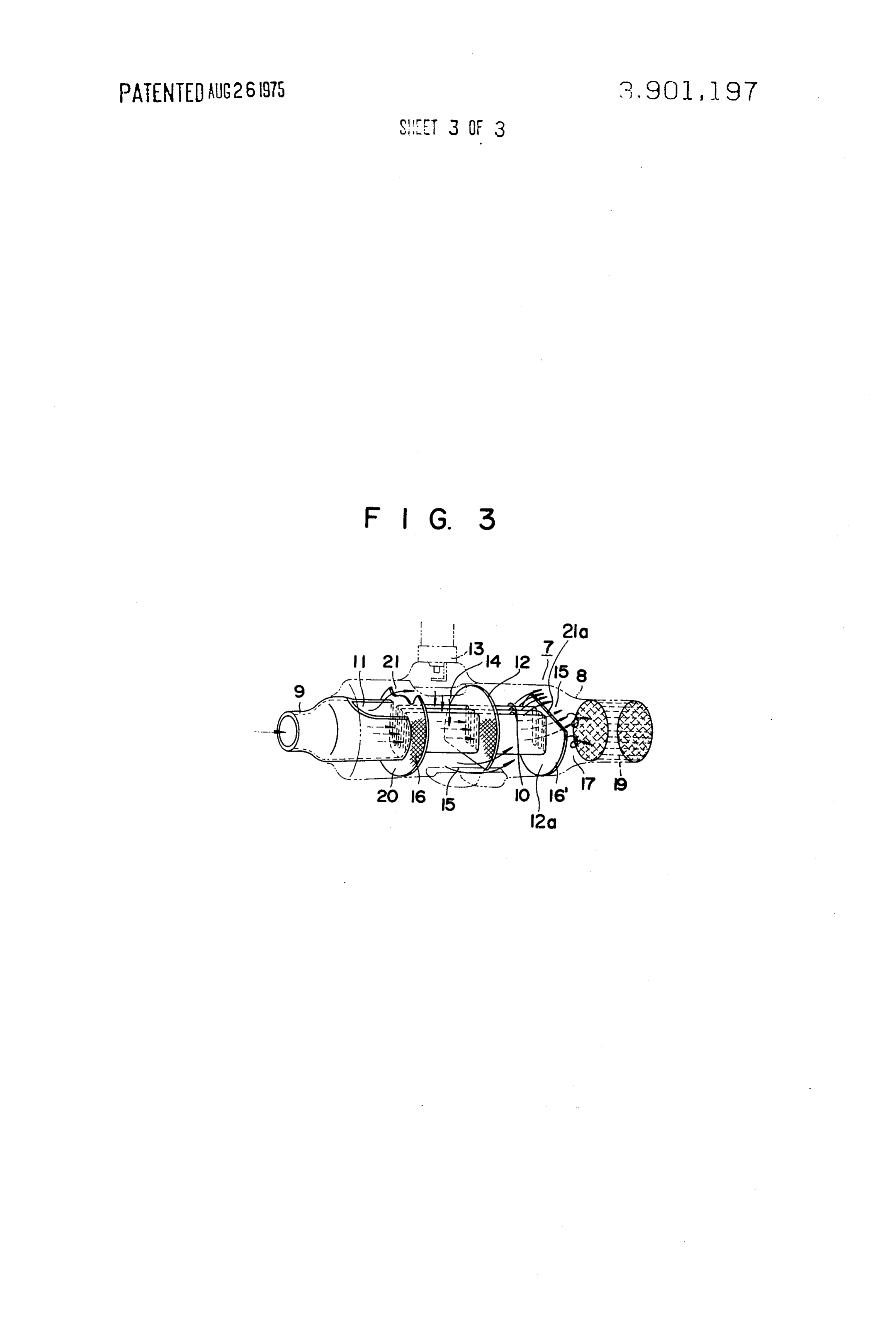
through heating of the fuel supply by burning one part FIG. 2D is across-sectional view of line D-D of FIG. of the same and by reacting the burnt part and the rest 25 2A; : ; , , as well with a catalyst. FIG. 3 is an oblique diagrammatic view illustrating In internal combustion engines burning hydrocarbon the essential parts of the device shown in FIG. 2. fuel oil, no attempts have heretofore been made to sup ply a fuel oil of reformed quality to the cylinder. The DETAILED DESCRIPTION OF A PREFERRED present invention has been worked out with the view in 30 EMBODIMENT mind that the ignition and combustion in an internal Referring now to the drawings, and more particularly combustion engine can be secured with an improved to FIG. 1 thereof, there is shown an internal combus efficiency of burning when a mixture of the products of tion engine equipped with the device of the present in decomposition and oxidation with various contents is vention. In the conventional manner, the mixture to be obtained by treating a part of the hydrocarbon fuel oil 35 sucked or drawn into a combustion chamber defined by supply in the presence of oxygen and supplying the a cylinder 4 is prepared by a carburetor 1, where the same thereafter to the cylinders of the engine. fuel is mixed with air. A part of the fuel from the fuel SUMMARY OF THE INVENTION tank, now shown, however, is diverted midway along its
path, so that instead of passing through the main suc
A primary object of the present invention therefore tion manifold 2, which is the main path for most of the is to provide a method for improving the fuel efficiency fuel from the main carburetor 1, and then into the com of an internal combustion engine while reducing harm bustion chamber of cylinder 4 of the internal combus ful contents from the exhaust gases thereof. tion engine 3, it goes from an auxiliary carburetor 5 and An object of the present invention therefore is to pro 45 through an auxiliary suction pipe 6, which is a sub-path, vide a method of reforming at least a part of the supply to an fuel reformer 7 of the present invention where fuel for an internal combustion engine into a mixture this part of the fuel is first reformed before being sup of the products of decomposition and oxidation to plied to the combustion chamber of the cylinder 4 achieve increased efficiency and simultaneously to re through another part of the auxiliary suction pipe des duce the amount of harmful contents in the emission ignated by the reference character 6'.
gas thereof. Turning now to FIGS. 2 and 3 for a more detailed Another object of the present invention is to provide study of the fuel reformer 7, an outer tube 8 thereof an apparatus for performing the method of reforming houses an inner tube 9 at one end, which is connected a part of the fuel being supplied to an internal combus to the auxiliary suction pipe 6, and a number of heat tion engine into a mixture of the products of decompo 55 conducting pipes 10, which communicate with the sition and oxidation. inner end of the inner tube 9. On one part of the top The foregoing objects and others are achieved ac periphery at the inner end of the inner tube 9 a notch cording to this invention by reforming a part of the sup 11 is provided which communicates with the reformer ply fuel flowing to an internal combustion engine into combustion chamber 14 through an opening 21 in a a mixture of the products of decomposition and oxida 60 transverse partition plate 20 disposed adjacent the tion and supplying this mixture together with the main inner end of the inner tube 9 and constituting one wall fuel supply being fed to the cylinders of the engine. of the reformer combustion chamber 14. The inside of More particularly, this is achieved by providing a sub the outer tube 8 is further divided into several sections path separate from the main fuel path leading from the by transverse partition walls 12, 12a disposed in paral fuel tank to the cylinder, which subpath consists of a 65 lel relation and spaced apart downstream of the parti first path and a second path, sending the greater part tion plate 20. In one of these sections, there is disposed of the fuel through the first path, diverting the remain an igniter 13, shown as an electrode spark plug, al ing part of the fuel mixture into the second path where though an electric heating wire may be used just as
Page 6
well. The partition walls defining the reformer combus ature of the blend of the mixture and the burnt gas in tion chamber 14 are provided with a passage 15, which the mixing chamber 17 as in the case where hot water communicates one section with another, thereby form is poured into cool water, will depend on the tempera ing a by-path for the mixture which flows into the outer ture and the proportion of hot water being poured, or tube 8 via the notch 11 of the inner tube 9 and the in other words, on the air/fuel ratio and volume ratio opening 21 in plate 20. Metal screens 16, each sup of the lean mixture to be ignited and burned. Thus, an ported by the partition plate 20 and partition wall 12a, appropriate volume ratio can be attained by choosing are inserted in the reformer combustion chamber 14 so an adequate ratio between the area of the opening 21 as to cover the openings 21 and 21a, which screens which leads from the notch 11 to the reformer combus serve to prevent backfire into the inner tube 9 and igni O tion chamber 14 and the sum of the entrance areas of tion of the mixed gas coming out of the heat the heat-conducting pipes 10, because the negative conducting pipes 10. pressures created in the engines act in the same man A gap is formed between the heat-conducting pipes ner. As for the air/fuel ratio, since the mixture is a lean 10, which terminate in a mixing or plenum chamber 17 one with a larger proportion of gaseous phase, as men formed near one end of the outer tube 8 and which 15 tioned above, experimental data show that when the leads to a catalyst chamber 19 disposed within a casing ratio of the volume to be diverted is less than 30%, the 18 connected to the end of the outer tube 8. The casing mixture will have an air/fuel ratio of about 20, and ac 18 is connected to the auxiliary suction pipe or conduit cordingly without taking any positive method to adjust 6' which opens into the entrance of the cylinder 4. the air/fuel ratio of a specified valve, the right tempera In the illustrated embodiment, the greater part of the ture for reformation to be explained later will be at mixture of air and fuel sucked into the cylinder goes tained.
from the main carburetor 1 through the main suction in this manner, a blend of the air/fuel mixture and the manifold 2 into the combustion chamber of cylinder 4. burnt gas flows into the catalyst chamber 19, where re Meanwhile, a part of the mixture passes from the auxili action takes place with the catalyst, and the fuel, with ary carburetor 5 into the auxiliary suction pipe 6, and 25 one part of it reformed into a blend of decomposition then via the fuel reformer 7, it also is sucked into the and oxidation products, can be supplied to the combus cylinder 4. The flow of mixture into the auxiliary suc tion chamber of cylinder 4.
tion pipe 6, which is a sub-path, is separated into a first To illustrate an example with pertinent numerical path, which extends from the inner tube 9 via the heat 30 data given, assuming the apparent air/fuel ratio of the conducting pipes 10 to the mixing or plenum chamber mixture prepared in the auxiliary carburetor 5 to be 3, 17, and into a second path, which extends from the and the opening area ratio to be 1:3, a blend with airff notch 11 of the inner tube 9 through the opening 21 uel being less than 3 flows from the tube 9 into the which leads to the reformer combustion chamber 14 heat-conducting tubes 10. About 25 percent of a lean set apart by the partition plate 20, then through the 35 mixture with an air/fuel ratio of approximately 20 flows outer tube 8 via the reformer combustion chamber 14, into the reformer combustion chamber 14, to be ig and finally to the mixing chamber 17. nited by the igniter 13 and completely burned, the The mixture obtained in the auxiliary carburetor 5 burning flame thereby heating the heat-conducting has a preset mix ratio, but the fuel in the mixture is a pipes 10 within the reformer combustion chamber 14. blend of a vaporized gaseous phase and a liquid phase. The air/fuel ratio of the above lean mixture decreases The gaseous phase can uniformly mix with the air, but 40 as low as approximately 13, when the absolute value of the liquid phase is partly sucked as droplets to be sus the manifold vacuum becames very high during such pended in the air and partly becomes a liquid flow times as idling or engine brake operation. Thus, the liq which spreads over the wall surface. The part of the uid phase fuel flowing together with air in the heat mixture which has gone into the inner tube 9 that flows 45 conducting pipes 10 is gradually vaporized to become along the top periphery of the inner tube 9 becomes a a gaseous phase in the mixture.
relatively lean mixture with a larger proportion of the The mixtures after converging in the mixing chamber gaseous phase, while the part of the mixture which 17 attain a temperature of 200-400°C and thus the re flows along the bottom periphery thereof becomes a action temperature of 150-500°C which is necessary relatively rich mixture having a larger proportion of the for reformation in the catalyst chamber 19 can be liquid phase. The former, or lean mixture, gets ignited 50 maintained. -
and burns in the course of flowing through the opening As described above, according to the present inven 21 into the outer tube 8 and going through the reformer tion, a definite proportion of a lean part, where the combustion chamber 14, and becomes a burnt gas, air/fuel ratio is approximately 20, in the fuel flowing whereupon it passes through the sections divided by the 55 from the fuel tank into the auxiliary suction pipe 6 is partition walls 12, while at the same time heating the picked up to be burned, the high heat of its combustion heat-conducting pipes 10, and then flows into the mix being utilized for heating up the fuel within the heat ing chamber 17. conducting pipes 10, so that the fuel can be perfectly The latter, or rich mixture, goes through the heat vaporized, and the converging fuel flowing from two conducting pipes 10, where, being heated by the burnt 60 paths can within the mixing chamber 17 be maintained gas, has its liquid phase vaporized into a gaseous phase, hot enough, or between 150 and 500°C, for reforma which then flows into a mixing chamber 17 to be tion.
blended with the burnt gas. In the present invention, therefore, depending on the The burnt gas, even after having its heat exchanged size of the opening 21 formed between the inner tube with the heat-conducting pipes 10, is still so hot that 65 9 and the reformer combustion chamber 14, the re even after vaporizing the mixture flowing in the heat forming conditions, such as the flow rate of the lean conducting pipes 10 by its heat, has a temperature fuel flowing through the opening 21 into the outer tube higher than that of the mixture. Therefore, the temper 8, the temperature in the combustion chamber 14, the
Page 7
temperature of the blend of the mixtures from the two a first fuel and air supply system connected to a com paths and the burnt gas can be appropriately set, and bustion chamber of said internal combustion en these conditions can be chosen to match the fuel to be gine, used, by making the opening 21 variable in size. a second fuel and air supply system for supplying a Thus, the present invention can remarkably improve fuel-air mixture;
the ignition and combustion in an internal combustion a fuel reformer connected to said second fuel and air engine by diverting and reforming a part of the fuel, supply system; and particularly its lean part, from the fuel path, utilizing a conduit for connecting said fuel reformer to said the heat of perfect burning of that part for reaction combustion chamber of said internal combustion with a catalyst, and thereby reforming the fuel to be O engine;
supplied to the cylinder. said fuel reformer comprising: Obviously, many modifications and variations of the a first and a second passage each connected to said present invention are possible in light of these teach second fuel and air supply system, a portion of said ings. It is to be understood therefore that within the fuel and air entering into said first passage and the scope of the appended claims, the invention may be 15 remaining portion entering into said second pas practiced otherwise than as specifically disclosed sage, said second passage being in heat exchange herein.
What is claimed as new and desired to be secured by relation with said first passage; an igniter in said Letters Patent of the U.S. is: first passage for igniting said portion of said fuel 1. A method for supplying combustible material to an and air and thereby heating said remaining portion internal combustion engine comprising the steps of: in said second passage; and feeding a first portion of fuel and a first portion of air a plenum chamber connected to said first and said to a fuel reformer; second passage for forming a confluence of said diverting a part of said first portion of fuel and said first passage and said second passage, said plenum first portion of air into a separate path within said 25 chamber being connected to said conduit. fuel reformer; 6. A device as set forth in claim 5, further comprising burning at least a portion of said part of said first por aandcatalyst interposed between said plenum chamber said conduit.
tion of fuel to form combustion products and utiliz ing the heat of said burning to heat up and vaporize ond 7. A device as set forth in claim 5, wherein said sec the remaining part of said first portion of fuel and 30 passage comprises:
to reform said first portion of fuel into a mixture an inlet chamber connected to said second fuel and including decomposition and oxidation products; air supply system; and and at least one heat-conducting pipe connected at one introducing said mixture including decomposition end thereof to said inlet chamber and at the other and oxidation products as well as a second portion 35 end thereof to said plenum chamber; and of fuel which has not been reformed and a second wherein said first passage comprises an outer shell portion of air into a combustion chamber of the en connected at one end thereof to said inlet chamber gine. and at the other end thereof to said plenum cham 2. The method of claim 1, wherein said first portion ber and enclosing said inlet chamber and said heat of said fuel is reformed into said mixture including de 40 conducting pipe; and composition and oxidation products in the presence of at least one partition disposed in said outer shell and a catalyst. dividing said outer shell into at least two sections, 3. The method of claim 1, further comprising the step said sections communicating with each other, said of: inlet chamber having an opening whereby said inlet converging said remaining part of said first portion of 45 chamber is in communication with said outer shell; fuel with said combustion products to reform said and first portion of said fuel into a mixture including wherein said igniter is disposed within one of said decomposition and oxidation products prior to in sections.
troducing said mixture into said combustion cham 8. A device as set forth in claim 7, wherein said re ber of the engine. 50 former further comprises a backfire preventing screen 4. The method of claim 3, further comprising the step disposed between said igniter and said opening, said of introducing said mixture including decomposition opening and said one of said sections wherein said ig and oxidation products to a catalyst. niter is disposed communicating only through said 5. A device for supplying combustible material to an SCee.
internal combustion engine comprising: 55 sk ck ck sk k
Provenance
- Collection
- Cited prior art
- Original PDF
- patentimages.storage.googleapis.com →
- Filed
- 1974-05-01
- Pages
- 7
- Method
- pdftotext (the PDF's own text layer) + pdftoppm 300dpi page scans
- Source
- Google Patents bibliographic record
- Granted
- 1975-08-26
- Inventors
- Masaaki Noguchi; Masaharu Sumiyoshi; Toyota Motor Corp
- Transcribed from
- patentimages.storage.googleapis.com →