patent · US5327874
Method and device for preparing fuel-air mixture for internal combustion engine
12 July 1994
Page 1 — bibliographic record
United States Patent (19) 11 Patent Number: 5,327,874 Pugachev et al. (45) Date of Patent: Jul. 12, 1994
54 METHOD AND DEVICE FOR PREPARING
FUELAR MIXTURE FOR INTERNAL FOREIGN PATENT DOCUMENTS COMBUSTION ENGINE 2613348 7/1980 Fed. Rep. of Germany .
75 Inventors: Alexandr V. Pugachev, ul. Davydova 493073 1/1975 U.S.S.R. . d.3, kv. 101, Moscow 121293; Vasiliy Primary Examiner-Tony M. Argenbright
N. Shatalov, Ryazan, both of Assistant Examiner-M. Macy
Attorney, Agent, or Firm-Collard & Roe 73) Assignee: Alexandr Vasilievich Pugachev, 57 ABSTRACT Ryazan, U.S.S.R.
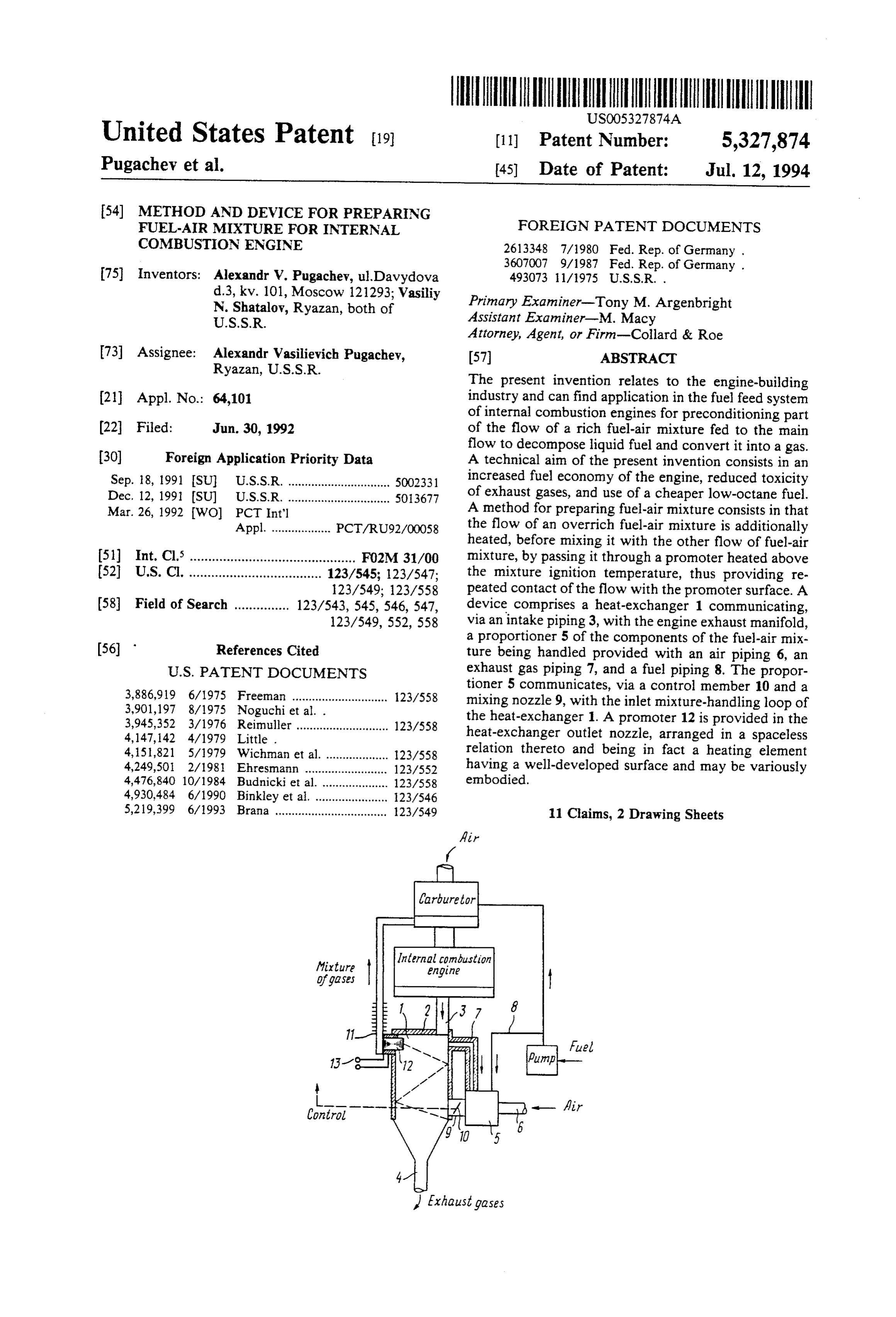
The present invention relates to the engine-building 21 Appl. No.: 64,101 industry and can find application in the fuel feed system of internal combustion engines for preconditioning part (22 Filed: Jun. 30, 1992 of the flow of a rich fuel-air mixture fed to the main flow to decompose liquid fuel and convert it into a gas.
(30) Foreign Application Priority Data A technical aim of the present invention consists in an Sep. 18, 1991 ISU U.S.S.R. ............................... SOO2331 increased fuel economy of the engine, reduced toxicity Dec. 12, 1991 ISU U.S.S.R. ............................... 50.13677 of exhaust gases, and use of a cheaper low-octane fuel. Mar. 26, 1992 WO) PCT Int'l A method for preparing fuel-air mixture consists in that Appl. .................. PCT/RU92/OOO58 the flow of an overrich fuel-air mixture is additionally heated, before mixing it with the other flow of fuel-air (51) Int. Cl. ............................................. FO2M 31/00 mixture, by passing it through a promoter heated above 52 U.S.C. .................................... 123/545; 123/547; the mixture ignition temperature, thus providing re 123/549; 123/558 peated contact of the flow with the promoter surface. A 58 Field of Search ............... 123/543, 545, 546, 547, device comprises a heat-exchanger 1 communicating, 123/549, 552, 558 via an intake piping 3, with the engine exhaust manifold, a proportioner 5 of the components of the fuel-air mix (56) References Cited ture being handled provided with an air piping 6, an
tioner 5 communicates, via a control member 10 and a 3,886,919 6/1975 Freeman ............................. 123/558 mixing nozzle 9, with the inlet mixture-handling loop of 3,901,197 8/1975 Noguchi et al. . the heat-exchanger 1. A promoter 12 is provided in the 3,945,352 3/1976 Reimuller ............................ 123/558 heat-exchanger outlet nozzle, arranged in a spaceless
4,151,821 5/1979 Wichman et al. ................... 123/558 relation thereto and being in fact a heating element 4,249,50 2/1981 Ehresmann ......................... 123/552 having a well-developed surface and may be variously 4,476,840 10/1984 Budnicki et al. .................... 123/558 embodied.
4,930,484 6/1990 Binkley et al. ...................... 23/546 5,219,399 6/1993 Brana .................................. 123/549 11 Claims, 2 Drawing Sheets
/fixture Internal combustion of gases
ZZZZZZZZZ
Exhaust gases
Page 2
Drawing sheet — no readable text.
Page 3
Drawing sheet — no readable text.
Page 4
taining gases and mixed with the other flow before
METHOD AND DEVICE FOR PREPARING being fed to the engine cylinder (DE A1 3,607,007). FUELAR MIXTURE FOR INTERNAL However, the fuel decomposition process is known COMBUSTION ENGINE commonly to proceed most efficaciously at a tempera ture about 850 C. which cannot be reached by the
TECHNICAL FIELD method in question.
The present invention relates in general to the engine Known in the present state of the art are devices for building industry and more specifically it concerns carrying into effect the methods for preparing fuel-air preparation of fuel-air mixture for internal combustion 10 mixture for internal combustion engines, comprising as engines. a rule heat-exchangers for preheating fuel-air mixture
BACKGROUND ART
by the heat of exhaust gases, and reactors with a cata lyst.
At present a routine method for preparing fuel-air To provide more efficient process for decomposition mixture consists in producing a hydrogen-containing 15 of the fuel molecules use is made of an additional heat gas from fuel and feeding said gas in the fuel-air mix ing arrangement of fuel-air mixture to a higher tempera ture. ture than that of exhaust gases. One prior-art method for preparing fuel-air mixture One prior-art device for preparing fuel-air mixture is for an internal combustion engine is known to effect in known to comprise an additional heating arrangement three stages, that is, at the first stage the fuel is partially with an ignition spark and a burner to which the fuel-air decomposed by virtue of the heat of exhaust gases, at mixture is fed and burns therein in an open fire, after the second stage the fuel is preheated by said gases, and which said mixture is fed to the reactor with a catalyst, at the third stage catalytic fuel decomposition occurs. wherein part of the liquid fuel molecules get decom To promote catalytic fuel decomposition at said stage posed (DE B2, 2,613,348).
the fuel is additionally preheated by exhaust gases (U.S. One more prior-art device for preparing the fuel-air Pat. No. 4,147,142). 25
However, the use of only the heat of exhaust gases for comprisefora internal mixture combustion engines is known to fuel decomposition is inadequate to attain an efficient close to the exhaust valves andinshaped reactor situated the exhaust manifold
and stable running of the fuel decomposition process. the side facing said exhaust valves) pipe running axially One more state-of-the-art method for preparing fuel and centrally of the exhaust pipe. Fuel, water, and air air mixture for an internal combustion engine is known 30 are fed, in a stringently fixed ratio, to the reactor nearby to consist in splitting the mixture into two flows, that is, its blind-end.
a greater main flow and a smaller auxiliary flow, sepa vice comprisesIn aitsheat-exchanger alternative version, the known de located also in the rating part of the mixture from the auxiliary flow, and exhaust pipe past the reactor as along the direction of burning the latter in order to heat and evaporate the flow of the engine exhaust gases (DE A1 3,607,007). remainder part of the auxiliary flow by the resultant 35 Low efficiency of the processes proceeding in the gases, followed by mixing both parts of the auxiliary known device has been discussed above.
flow and feeding an integrated flow to the catalytic It is common knowledge that high temperatures of chamber. Before being fed to the combustion chamber the preconditioned auxiliary flow of the mixture is inter exhaust gases occur only at the first instant of the ex mixed with the main flow of the fuel-air mixture (U.S. haust stroke, then their temperature drops abruptly. Pat. No. 3,901,197). Taking into account the transient nature of the exhaust Use of an open fire, according to the known method, process (which equals one-fourth of a crankshaft revo for burning part of the fuel from the fuel-air mixture lution per two complete revolutions thereof), as well as adds to the efficiency of thermal fuel decomposition, of the fact that the temperature of a heat-transfer agent however, it increases fuel consumption and is hazard 45 used for preconditioning the fuel-air mixture without its ous. A danger of flame travel and an outbreak of fire preheating is as low as 750° C. compared to 900° C. with arises when an engine runs unsteadily or misses, as the preheating. One cannot expect a stable process of de velocity of flame travel in the fuel-air mixture may composition of the liquid fuel molecules. exceed the flow velocity of the mixture itself. Furthermore, having impinged upon the front reactor Moreover, unburnt hydrocarbons of the CH-2 50 wall at the hottest spot thereof, the fuel particles there type are left after burning an enriched mixture, which after might not collide with said wall or might come in are deposited in the catalyst pores as soot and coke, thus contact with colder reactor areas, that is, only a once putting the catalyst out of order. through process of decomposition of the fuel molecules As is evident from specification of the heretofore is possible, which is quite ineffective. On the other known methods for decomposition of liquid fuel, said 55 hand, provision of a special pump for feeding the fuel methods involve use of catalysts which are not only air mixture to the reactor adds to the cost of the device expensive components of the fuel-air preparation device as a whole, whereas the higher temperature of exhaust but also require periodical replacement, inasmuch as gases involves increased fuel consumption. anti-knocking dopes present in the fuel are detrimental A device for preconditioning the fuel-air mixture for to catalysts. internal combustion engines that is nearest in spirit to Still one more prior-art method for preparing fuel-air that herein-proposed, comprises a double-loop heat mixture for internal combustion engines is known to be exchanger having an inlet and an outlet piping, a pro the nearest in spirit to the herein-proposed method and portioner of the components of the mixture being consists in that two flows of fuel-air mixture are estab treated, and an igniter provided at the outlet of the first lished. One of the two flows is overenriched below the 65 loop of the heat-exchanger before the catalyst-contain ignition range and heated to a temperature of 400-800 ing chamber. The input and output pipings of the sec C. with exhaust gases having a temperature of about ond loop of the heat-exchanger are connected respec 750 C. to obtain carbon monoxide and hydrogen-con tively to the engine exhaust pipe and to the surrounding
Page 5
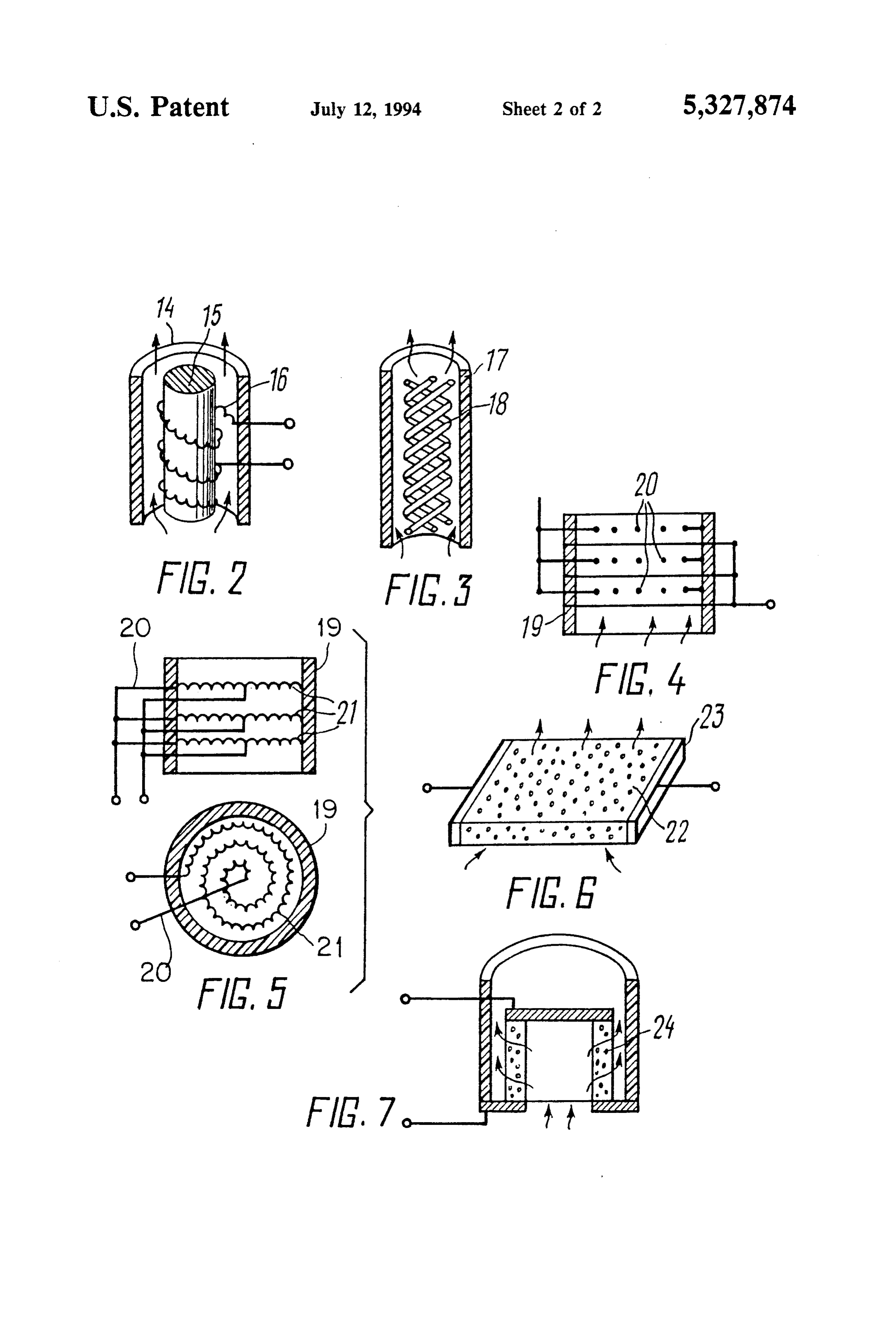
atmosphere, and the mixing nozzle of the proportioner The enlarged heatable surface area of the promoter is connected to the first heat-exchanger loop through a may be established by:
controlled member (SU All 493,073). a number of wire rows placed consecutively in a As is evident from the above discussion of the hereto zigzag pattern in the housing as along the flow of the fore-known devices, use is therein made of catalysts on fuel-air mixture, the wire rays of each next row mutu a platinum support which renders said devices too ex ally intersecting in plan;
pensive, whereas use of a heat-transfer agent hotter than a number of parallel coils wound in plan into the the engine exhaust gases makes the device in question Archimedean spiral and placed consecutively in a cylin uneconomical, too. drical housing as along the flow of the fuel-air mixture;
Disclosure of the Invention a porous spatial flat element;
a porous spatial cylindrical element.
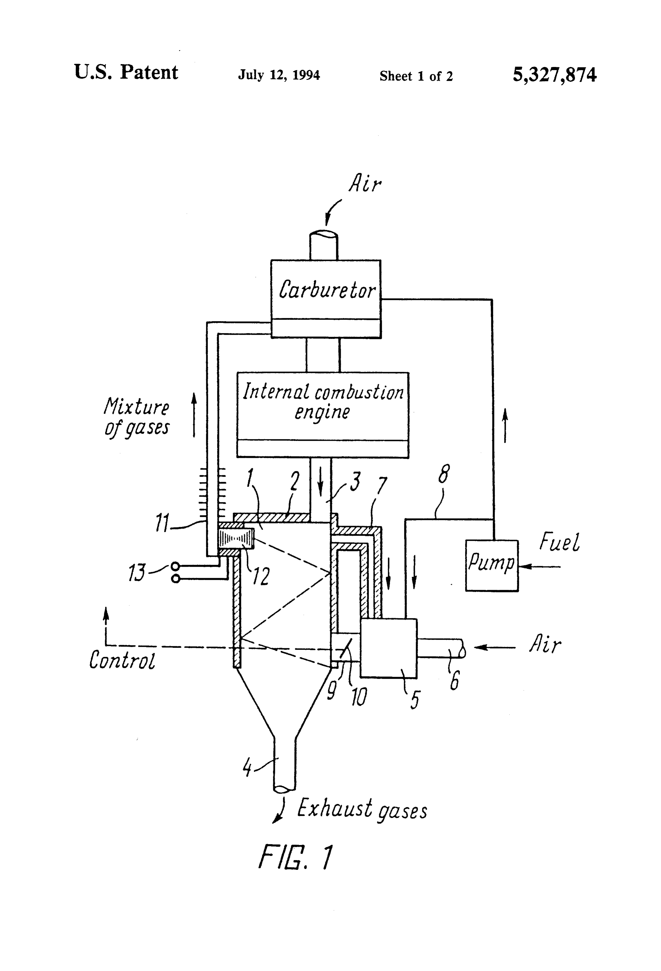
The present invention has for its principal object to prepare the fuel-air mixture for internal combustion BRIEF DESCRIPTION OF THE DRAWINGS engines without the use of an expensive catalyst, addi To promote the understanding of the present inven tional igniters or pumps, and to render the internal com 15 tion given below, a specific exemplary embodiment bustion engine more economical in fuel consumption thereof with reference to the accompanying drawings is and to reduce the toxicity of exhaust gases. provided, wherein:
As far as the method is concerned, the foregoing FIG. 1 is a schematic functional diagram of the de object is accomplished due to the fact that there are 20 vice, according to the invention; formed two flows of the fuel-air mixture. One of which is overenriched below the ignition range, preheated by struction2having
FIG. is a first embodiment of the promoter con a rod-wound coil;
exhaust gases to obtain carbon monoxide and hydrogen containing gases, and mixed with the other flow of the struction featured by embodiment
FIG. 3 is a second the of the promoter con wound-together coils;
fuel-air mixture before being fed to the engine cylinders. 25 FIG. 4 is a third embodiment of the promoter The flow of the overrich fuel-air mixture is additionally struction featuring zigzag-arranged wire rows; con heated before mixing it with the other flow, by passing FIG. 5 is a fourth embodiment of the promoter con it through a promoter heated above the mixture ignition struction featuring the coils wound in plan along the temperature, whereupon thermal cracking of the fuel is Archimedean performed in the boundary layer of said promoter by 30 FIG. 6 is a spiral; fifth embodiment of the promoter con multiple repeated fuel contact with the promoter sur struction featuring a porous spatial flat element; and face.
An additional enhancement of the engine efficiency struction featuring aembodiment
FIG. 7 is a sixth porous of the promoter con spatial cylindrical element.
and fuel economy is attained due to adding to the fuel air mixture being handled such additives as exhaust 35 BEST METHOD OF CARRYING OUT THE gases, water, and a low-octane fuel. INVENTION As far as the device is concerned, the foregoing ob The method for preparing the fuel-air mixture for ject is accomplished due to the fact that the device for internal combustion engines consists in that there are preparing fuel-air mixture for internal combustion en formed two flows of the fuel-air mixture, one of which gines comprises a double-loop heat-exchanger having 40 an inlet piping and an outlet piping, a proportioner of exhaustis overenriched below the ignition range, heated by the components of the mixture being handled, and an gen-containing gases to produce carbon monoxide and hydro incandescence element provided at the heat-exchanger preheated abovegases, the and is then fed to a promoter mixture ignition point.
outlet. The inlet and outlet pipings of the gas-handling loop of the heat-exchanger are connected respectively 45 Fuel particles on getting onto the activator are to the engine exhaust pipe and to the surrounding atmo brought in contact with the hot surface thereof repeat sphere, whereas the proportioner mixing nozzle com edly under a deficit of oxidant leads to a repeated pro municates, via a control member, with the mixture-han cess of partial oxidation of the molecules of organic fuel dling loop of the heat exchanger. The incandescence (C8H18). Thus, the molecule starts decomposing, the element is of the non-igniting type and appears as a 50 separated molecules of C and H are combined with promoter having an enlarged heatable surface area and oxygen, that is, the partial oxidation reaction proceeds. is accommodated in the outlet nozzle of the heat exchanger mixture-handling loop in a spaceless relation thereto. The promoter can be mounted pivotally about The original molecule turns into a lighter structure its own axis. 55 and gaseous CO, CO2 and H2 are disengaged. Thus, an The promoter may vary both in construction and endothermic decomposition reaction occurs.
shape.
In particular, the promoter may be embodied as fol malExhaust gases and water may participate in the ther decomposition process.
lows:
as a cylinder accommodating a rod coaxial therewith, added When part of the CO2-containing exhaust gases are both the cylinder and rod being made from a heat-resist decomposition to the fuel-air mixture being prepared, a CO2 ant insulant, a single- or multiturn coil being wound reaction will occur; onto the rod and snugly applied between the cylinder CO2C= CO-CO.
and the rod;
as a ceramic tube accommodating a cluster of coils 65 Water decomposition occurs concurrently; wound together and having their axis parallel to that of the tube;
as a heat-resistant electrical-insulant housing.
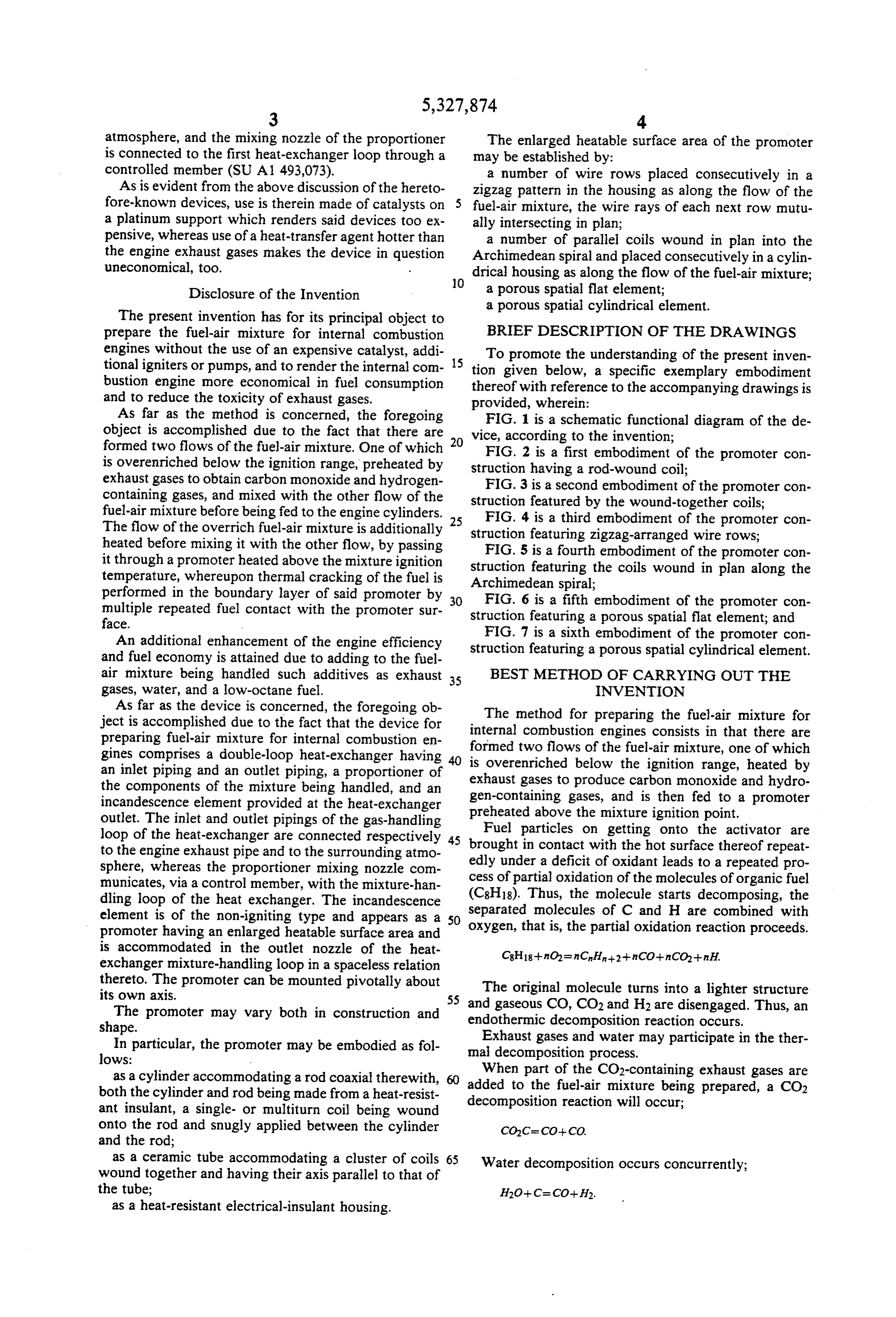
Page 6
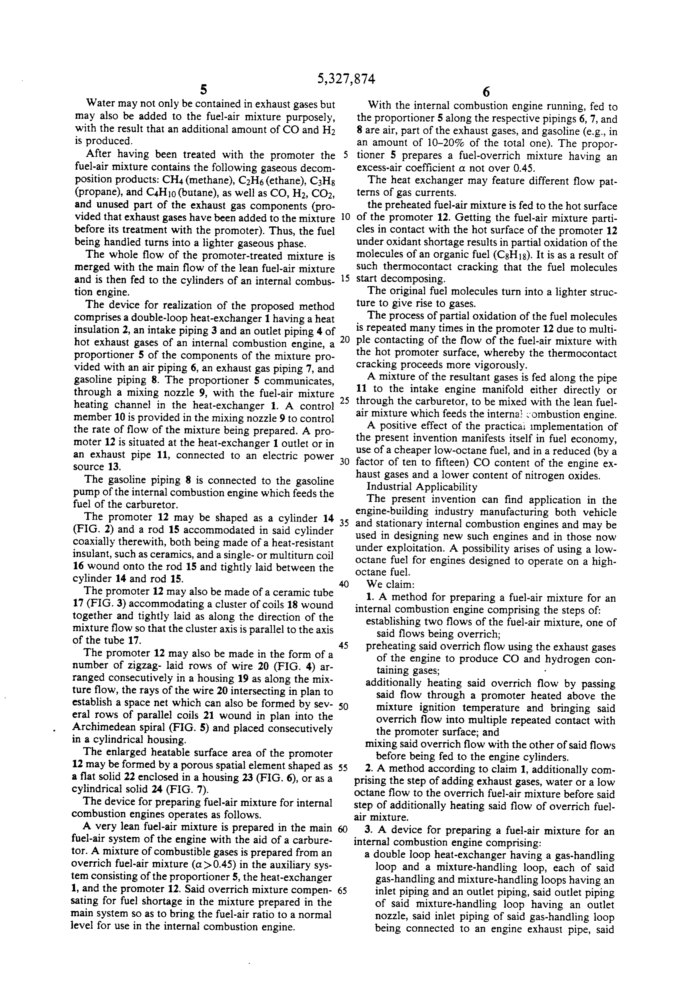
Water may not only be contained in exhaust gases but With the internal combustion engine running, fed to may also be added to the fuel-air mixture purposely, the proportioner 5 along the respective pipings 6, 7, and with the result that an additional amount of CO and H2 8 are air, part of the exhaust gases, and gasoline (e.g., in is produced. an amount of 10-20% of the total one). The propor After having been treated with the promoter the tioner 5 prepares a fuel-overrich mixture having an fuel-air mixture contains the following gaseous decom excess-air coefficient a not over 0.45. position products: CH4 (methane), C2H6 (ethane), C3H8 The heat exchanger may feature different flow pat (propane), and C4H10 (butane), as well as CO, H2, CO2, terns of gas currents.
and unused part of the exhaust gas components (pro the preheated fuel-air mixture is fed to the hot surface vided that exhaust gases have been added to the mixture O of the promoter 12. Getting the fuel-air mixture parti before its treatment with the promoter). Thus, the fuel cles in contact with the hot surface of the promoter 12 being handled turns into a lighter gaseous phase. under oxidant shortage results in partial oxidation of the The whole flow of the promoter-treated mixture is molecules of an organic fuel (C8H18). It is as a result of merged with the main flow of the lean fuel-air mixture 15 such thermocontact cracking that the fuel molecules and is then fed to the cylinders of an internal combus start decomposing.
tion engine. The original fuel molecules turn into a lighter struc The device for realization of the proposed method ture to give rise to gases.
comprises a double-loop heat-exchanger 1 having a heat The process of partial oxidation of the fuel molecules insulation 2, an intake piping 3 and an outlet piping 4 of 20 is repeated many times in the promoter 12 due to multi hot exhaust gases of an internal combustion engine, a ple contacting of the flow of the fuel-air mixture with proportioner 5 of the components of the mixture pro the hot promoter surface, whereby the thermocontact vided with an air piping 6, an exhaust gas piping 7, and cracking proceeds more vigorously.
gasoline piping 8. The proportioner 5 communicates, A mixture of the resultant gases is fed along the pipe through a mixing nozzle 9, with the fuel-air mixture 25 11 to the intake engine manifold either directly or heating channel in the heat-exchanger 1. A control through the carburetor, to be mixed with the lean fuel member 10 is provided in the mixing nozzle 9 to control airAmixture which feeds the internal combustion engine. positive effect of the practical implementation of the rate of flow of the mixture being prepared. A pro moter 12 is situated at the heat-exchanger 1 outlet or in the present invention manifests itself in fuel economy, an exhaust pipe 11, connected to an electric power 30 use of a cheaper low-octane fuel, and in a reduced (by a source 13. factor of ten to fifteen) CO content of the engine ex The gasoline piping 8 is connected to the gasoline haust gases and a lower content of nitrogen oxides. Industrial Applicability pump of the internal combustion engine which feeds the The present invention can find application in the fuel of the carburetor.
The promoter 12 may be shaped as a cylinder 14 35 and stationary internal industry manufacturing both vehicle (FIG. 2) and a rod 15 accommodated in said cylinder used in designing new combustion such engines engines and may be and in those now coaxially therewith, both being made of a heat-resistant insulant, such as ceramics, and a single- or multiturn coil under exploitation. A possibility arises of using a low octane fuel for engines designed to operate on a high 16 wound onto the rod 15 and tightly laid between the octane fuel.
cylinder 14 and rod 15. We claim:
The promoter 12 may also be made of a ceramic tube 1. A method for preparing a fuel-air mixture for an 17 (FIG. 3) accommodating a cluster of coils 18 wound internal combustion engine comprising the steps of: together and tightly laid as along the direction of the establishing two flows of the fuel-air mixture, one of mixture flow so that the cluster axis is parallel to the axis said flows being overrich; of the tube 17.
The promoter 12 may also be made in the form of a 45 preheating said overrich flow using the exhaust gases of the engine to produce CO and hydrogen con number of zigzag laid rows of wire 20 (FIG. 4) ar taining gases;
ranged consecutively in a housing 19 as along the mix additionally heating said overrich flow by passing ture flow, the rays of the wire 20 intersecting in plan to said flow through a promoter heated above the establish a space net which can also be formed by sev 50 mixture ignition temperature and bringing said eral rows of parallel coils 21 wound in plan into the overrich flow into multiple repeated contact with Archimedean spiral (FIG. 5) and placed consecutively the promoter surface; and in a cylindrical housing. mixing said overrich flow with the other of said flows The enlarged heatable surface area of the promoter before being fed to the engine cylinders. 12 may be formed by a porous spatial element shaped as 55 2. A method according to claim 1, additionally com a flat solid 22 enclosed in a housing 23 (FIG. 6), or as a prising the step of adding exhaust gases, water or a low cylindrical solid 24 (FIG. 7). octane flow to the overrich fuel-air mixture before said The device for preparing fuel-air mixture for internal step of additionally heating said flow of overrich fuel combustion engines operates as follows. air mixture.
A very lean fuel-air mixture is prepared in the main 3. A device for preparing a fuel-air mixture for an fuel-air system of the engine with the aid of a carbure internal combustion engine comprising: tor. A mixture of combustible gases is prepared from an a double loop heat-exchanger having a gas-handling overrich fuel-air mixture (a) 0.45) in the auxiliary sys loop and a mixture-handling loop, each of said tem consisting of the proportioner 5, the heat-exchanger gas-handling and mixture-handling loops having an 1, and the promoter 12. Said overrich mixture compen 65 inlet piping and an outlet piping, said outlet piping sating for fuel shortage in the mixture prepared in the of said mixture-handling loop having an outlet main system so as to bring the fuel-air ratio to a normal nozzle, said inlet piping of said gas-handling loop level for use in the internal combustion engine. being connected to an engine exhaust pipe, said
Page 7
outlet piping of said gas-handling loop being con 7. The device according to claim 5, wherein said coil nected to the surrounding atmosphere; is a single turn coil wound on said rod and disposed a proportioner for preparing the components of the between said cylinder and said rod. fuel-air mixture, said proportioner having a mixing 8. The device according to claim 3, wherein said nozzle communicating with said mixture-handling 5 promoter comprises a ceramic tube; loop of said double loop heat-exchanger; a cluster of coils wound together and disposed within a control member coupled to said mixture nozzle of said tube and having their axes parallel to the axis said proportioner for controlling communication of the tube.
between said proportioner and said mixture-han 9. The device according to claim 3, wherein said dling loop; and 10 promoter comprises a heat-resistant insulated housing a promoter comprising an incandescence element and said enlarged heatable surface comprises a plurality disposed within said outlet nozzle of said mixture of wire rows laid consecutively in a zigzag pattern in handling loop in a spaced-apart relation thereto, said heat-resistant housing, and along the flow of the said incandescence element being a non-igniting fuel-air mixture, said wire rows of each next row inter type and having an enlarged heatable surface area. 15 secting in the same plane.
4. The device according to claim 3, wherein said 10. The device according to claim 3, wherein the promoter is pivotable about its own axis. enlarged heatable surface area of said promoter com 5. The device according to claim 3, wherein said promoter comprises a cylinder, said promoter having a prises same a plurality of rows of parallel coils wound in the plane into Archimedean spirals, and said spirals rod arranged coaxially therethrough, and wherein said 20 laid consecutively in a cylindrical housing, along the cylinder and said rod are made of a heat-resistant insula flow of the fuel-air mixture.
tion, said rod having a coil wound thereon disposed 11. The device according to claim 3, wherein said between said cylinder and said rod. enlarged heatable surface area of said promoter com 6. The device according to claim 5, wherein said coil prises a porous, spatial flat element enclosed in a hous is a multiturn coil wound on said rod and disposed 25 ing.
between said cylinder and said rod. k k k k
Provenance
- Collection
- Cited prior art
- Original PDF
- patentimages.storage.googleapis.com →
- Filed
- 1992-06-30
- Pages
- 7
- Method
- pdftotext (the PDF's own text layer) + pdftoppm 300dpi page scans
- Source
- Google Patents bibliographic record
- Granted
- 1994-07-12
- Inventors
- Alexandr V. Pugachev; Vasiliy N. Shatalov
- Transcribed from
- patentimages.storage.googleapis.com →