patent · US4475483
Catalyst delivery system
9 October 1984
Page 1 — bibliographic record
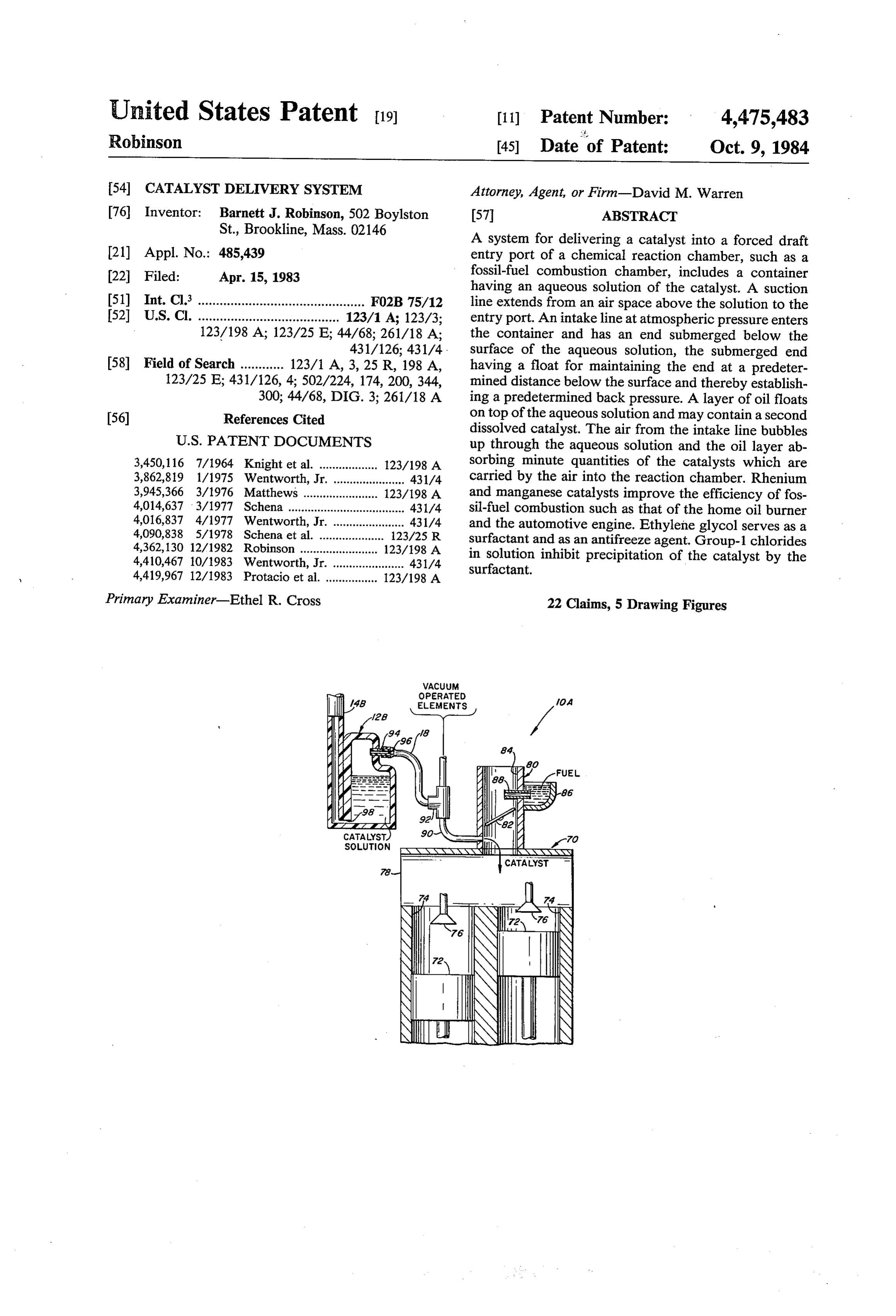
United States Patent (19) 11 Patent Number: 4,475,483 Robinson (45) Date of Patent: Oct. 9, 1984 54 CATALYST DELIVERY SYSTEM Attorney, Agent, or Firm-David M. Warren 76 Inventor: Barnett J. Robinson, 502 Boylston 57 ABSTRACT St., Brookline, Mass. 02146 A system for delivering a catalyst into a forced draft 21) Appl. No.: 485,439 entry port of a chemical reaction chamber, such as a (22 Filed: Apr. 15, 1983 fossil-fuel combustion chamber, includes a container having an aqueous solution of the catalyst. A suction 51) Int. Cl. .............................................. F02B 75/12 line extends from an air space above the solution to the 52 U.S.C. ....................................... 123/1 A; 123/3; entry port. An intake line at atmospheric pressure enters 123/198 A; 123/25 E; 44/68; 261/18 A; the container and has an end submerged below the 431/126; 431/4. surface of the aqueous solution, the submerged end 58 Field of Search ............ 123/1 A, 3, 25 R, 198 A, having a float for maintaining the end at a predeter 123/25 E; 431/126, 4: 502/224, 174, 200, 344, mined distance below the surface and thereby establish 300; 44/68, DIG. 3; 261/18 A ing a predetermined back pressure. A layer of oil floats 56) References Cited on top of the aqueous solution and may contain a second dissolved catalyst. The air from the intake line bubbles
3,450,116 7/1964 Knight et al. .................. 123/198 A sorbing minute quantities of the catalysts which are 3,862,819 1/1975 Wentworth, Jr. ...................... 431/4 carried by the air into the reaction chamber. Rhenium 3,945,366 3/1976 Matthews ......... 123/198A and manganese catalysts improve the efficiency of fos 4,014,637 3/1977 Schena .................................... 431/4 sil-fuel combustion such as that of the home oil burner 4,016,837 4/1977 Wentworth, Jr. ... 431/4 and the automotive engine. Ethylene glycol serves as a 4,090,838 5/1978 Schena et al. 123/25 R surfactant and as an antifreeze agent. Group-1 chlorides 4,362,130 12/1982 Robinson .............. ... 123/198A in solution inhibit precipitation of the catalyst by the 4,410,467 10/1983 Wentworth, Jr. ...................... 431/4 surfactant.
Primary Examiner-Ethel R. Cross 22 Claims, 5 Drawing Figures
WACUUM
OPERATED
Page 2
Drawing sheet — no readable text.
Page 3
Drawing sheet — no readable text.
Page 4
CATALYST DELVERY SYSTEM the suction line. A float is attached to the suction line for floating the end of the suction line at a predeter
BACKGROUND OF THE INVENTION mined depth to establish a predetermined back pressure, whereby the bubbling is regulated by the difference
Water has been used to improve fossil fuel combus between the suction pressure and the atmospheric pres tion in both automotive engines and oil-fired furnaces. sure independently of the depth of the water. The dis In the case of automotive engines, wherein gasoline is solving of the rhenium and manganese catalysts pro burned in air, the air has been mixed with water to vides for a fine dispersion of the catalyst at the molecu increase its humidity prior to the mixing of the gasoline with the air. In the case of oil-fired furnaces, steam has 10 lar level which permits the absorportion of minute quantities of finely dispersed catalyst into the air bub been used to atomize the oil. Various techniques have been used for the mixing of water with the constituent bles. Intimate mixing of the catalysts with the constitu ent components of the combustion process is thereby substances of the combustion process. These techniques attained. The flask with its floating inlet line and outlet include the spraying of water into a chamber of air as taught in U.S. Pat. No. 3,107,657 which issued in the 15 Suction line may be used for other catalysts. Liquids name of D. Cook, the passing of water through gasoline other than water, such as alcohol, may be utilized. as taught in U.S. Pat. No. 3,724,429 which issued in the In a preferred embodiment of the invention, per name of N. Tomlinson, the forcing of a stream of fine rhenic acid is dissolved in the water to serve as a cata bubbles of air through water as taught in U.S. Pat. No. lyst. The perrhenic acid decomposes at temperatures 3,767,172 which issued in the name of H. Mills, and the 20 well below that of the deflagration temperatures of the injection of a fine spray of water into a gas flame as foregoing engine and furnace and, accordingly, is be taught in U.S. Pat. No. 3,809,523 which issued in the lieved to make molecular rhenium available to the burn name of W. Varekamp. A more recent technique, ing fuel, thereby enhancing the combustion. Thus, it is taught in U.S. Pat. No. 3,862,819 which issued in the seen that rhenium metal has been combined with oxy name of F. Wentworth, involves the diversion of a small 25 gen, dissolved in water, carried off by air, and released portion of the inlet air to a combustion chamber, and the as a metal at the combustion site at a temperature lower bubbling of the air through water covered with a layer than the combustion temperature. Other suitable com of oil. The bubbling of air through a solution of a plati num compound is taught in U.S. Pat. No. 4,295,816 pounds carbonyl of rhenium include the metaperrhenates and halides. A surfactant such as ethylene glycol which issued in the name of B. J. Robinson. 30 promotes fractionation of the rhenium catalyst from the
A problem arises with the techniques taught by the solution first four of the aforementioned patents in that they during the bubbling of the gas therethrough. A require the continuous replenishment of the water sup group-1factant chloride counteracts the tendency of the sur to precipitate the catalyst.
ply. While water use has been reduced in the system of the aforementioned Wentworth patent, it is desirable to 35 It is noted that the rhenium is beneficial in two re increase the efficiency of the combustion to a greater spects. In addition to serving as a catalyst for more extent than that provided by Wentworth. Also, as noted collaplete combustion of hydrocarbon in air, rhenium by Wentworth, the systems of the first four of the afore also tends to alter the chemical composition of a hydro mentioned patents with the larger use of water may carbon by reforming a nonaromatic hydrocarbon mole cause damage such as the shortening of the life of an 40 cule to an aromatic hydrocarbon molecule. In the burn automotive engine. ing of gasoline in an automotive engine, a pinging may SUMMARY OF THE INVENTION be noticed when the octane of the gasoline is exces sively low with respect to the compression ratio of the
In accordance with the invention, the aforemen engine. When rhenium is used with gasoline, the forego tioned problems are overcome and other advantages are 45 ing reforming of the hydrocarbon molecule results in a provided by a system incorporating one or more cata raising lysts which are dissolved in liquids through which a gas uniformofratetheofburning.
octane, and a better controlled, more is bubbled for subsequent passage into a chamber into an automotive engineThus, the aspiration of rhenium wherein a chemical reaction, such as the combustion of a great advantage. which providesthea tendency reduces smooth to ping, running a fossil fuel, takes place. In a preferred embodiment of 50 the invention utilized for the delivery of minute quanti engine.
vides
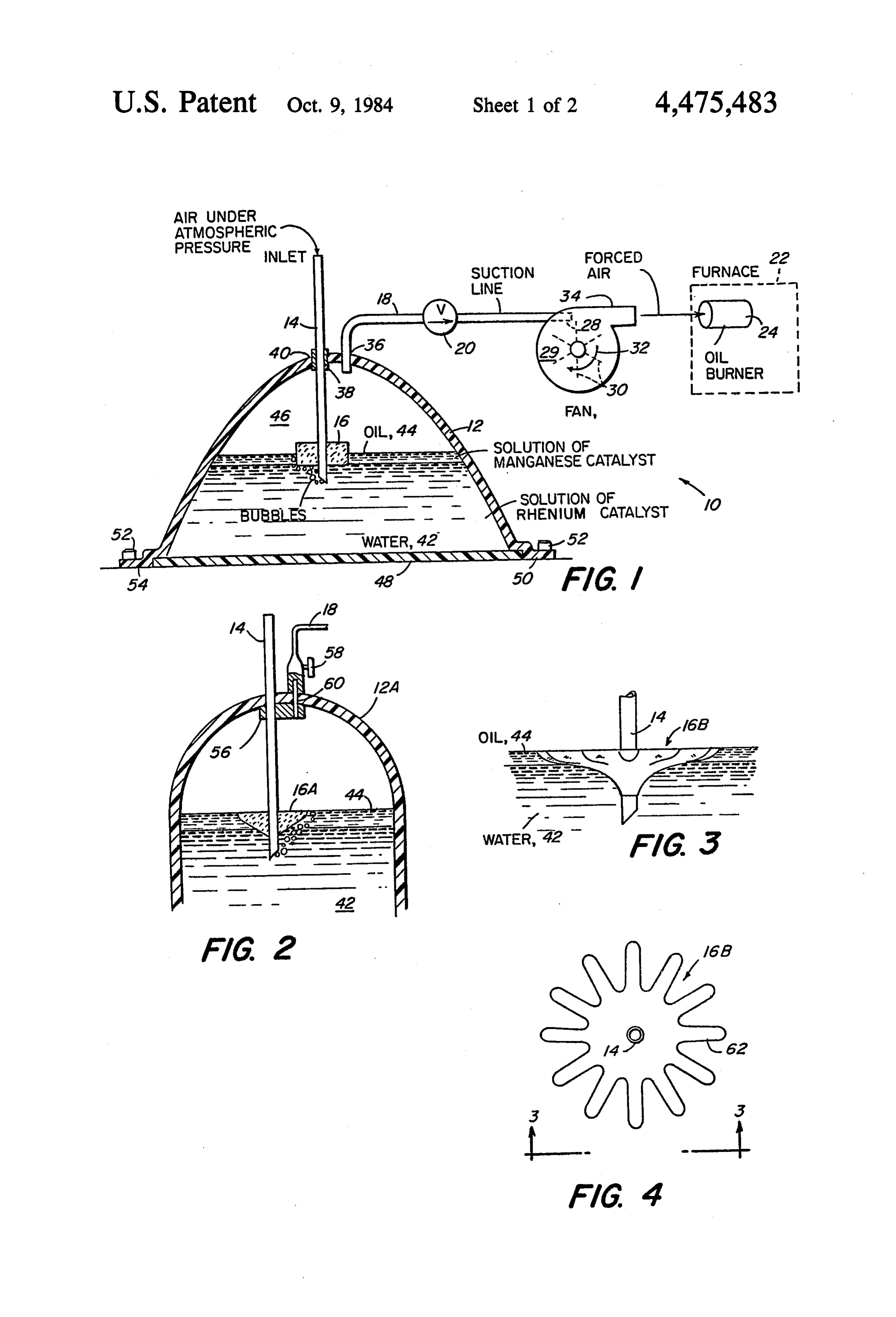
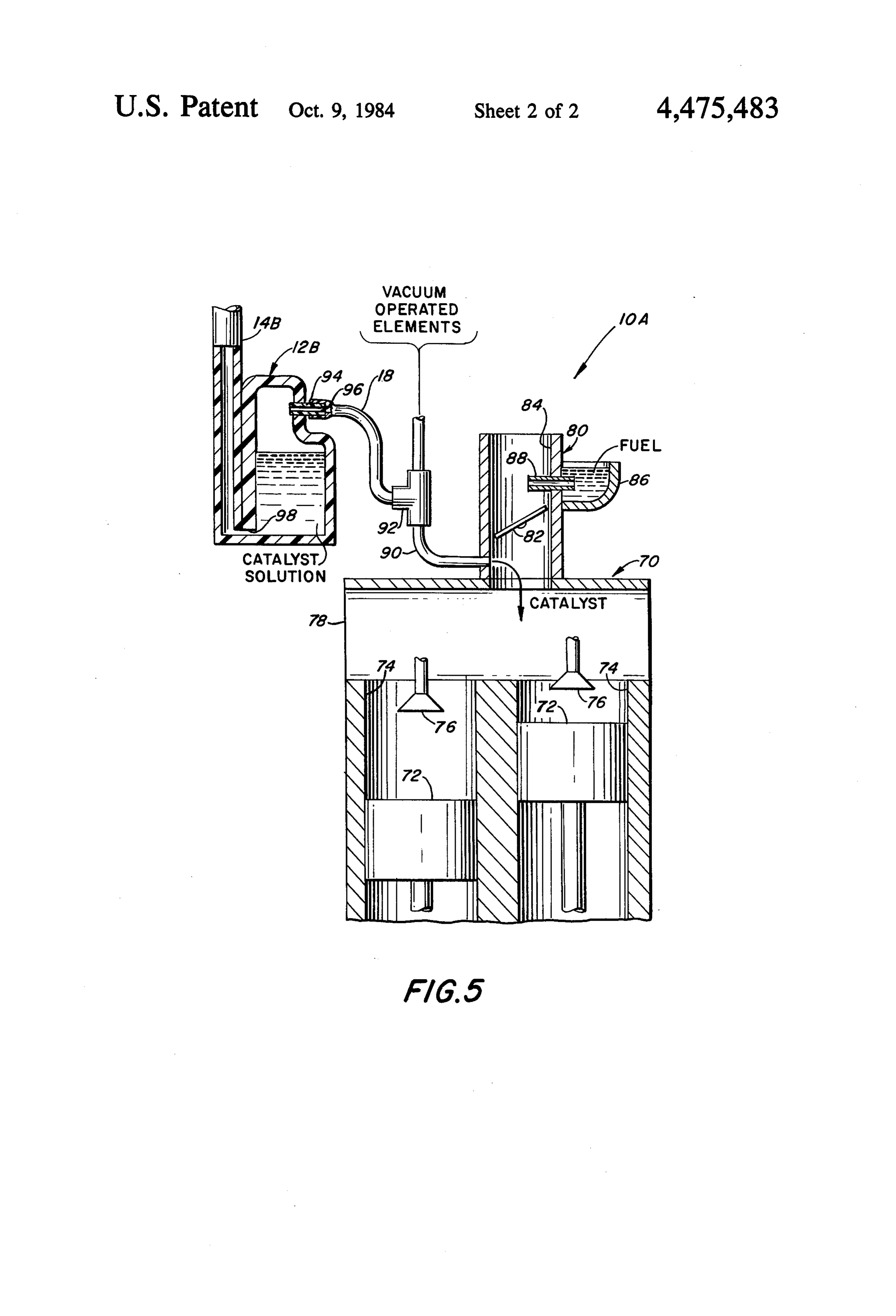
The foregoing reformation process also pro for a more uniform flame front in an oil-fired ties of water containing a catalyst to the oil burner of a furnace which aids in the efficient burning of the fuel. furnace, the system of the invention comprises a flask containing water in which has been dissolved a catalyst, BRIEF DESCRIPTION OF THE DRAWING namely, a compound of rhenium. A petroleum-based oil 55 layer is floated on top of the water to control the bub The aforementioned aspects and other features of the bling and prevent a splattering and the attendant forma invention are explained in the following description tion of aerosols. If desired, a second catalyst which is taken in connection with the accompanying drawing: insoluble in water, such as manganese naphthanate, may wherein - be dissolved in the oil. 60 FIG. 1 is a diagrammatic illustration of a catalyst In both the cases of an automotive engine and an delivery system in accordance with the invention; oil-fired furnace, there is a forced air intake port, or FIG. 2 shows an alternative embodiment of the top suction port, to which is attached a suction line from an portion of a flask of FIG. 1;
airspace in the flask above the layer of oil. An intake FIGS. 3 and 4 show, respectively, a side view and a line brings air at atmospheric pressure into the flask, an 65 plan view of an alternative embodiment of a float of end of the intake line being submerged below the sur FIG. 1; and face of the water to provide for the bubbling of air FIG. 5 is a stylized sectional view of a portion of an through the water and oil in response to the suction of automotive engine incorporating the invention.
Page 5
DESCRIPTION OF THE PREFERRED
with the consequent conservation of the liquids, the oil 44 and the water 42 with the catalyst dissolved therein.
EMBODEMENT The flask 12 is made of a rigid material impervious to With reference to FIG. 1, there is shown a catalyst the liquids contained therein. In the case of the pre delivery system 10 constructed in accordance with the ferred embodiment wherein oil and water are contained invention, the system 10 comprising a flask 12, a tube 14 within the flask 12, the flask 12 may be made of glass or, having a float 16 positioned near the lower end thereof, preferably, of a shatter-resistant plastic, which is also a tube 18 having a shut-off valve 20, a furnace 22 with resistant to the chemicals contained within the flask. an oil burner 24 therein, and a centrifugal fan 26 which The float 16 is in the form of a right circular cylinder forces air into the burner 24. The tube 18 has an end 28 10 made of foamed polyurethane, and has an aperture which is passed through an aperture in a housing 29 of therein for the passage of the tube 14. In assembling the the fan 26, the end 28 facing in the downstream direc flask 12, the float 16 is first positioned upon the tube 14, tion of the airflow and thereby inducing suction in the and then the tube 14 is passed through the open bottom tube 18. Vanes 30 rotate in the direction of an arrow 32 of the flask 12 and slid through the tube segment 38. A to draw air in at the port 32, and to discharge the air via 15 cover plate 48 is then adhesively secured to a rim 50 a port 34. The tube 18 serves as an outlet of the flask 12 around the bottom edge of the flask 12. Bolts 52 pass and is secured at an aperture 36 of the flask 12. The tube through a flange 54 of the flask 12 for securing the flask 14 is slidably secured to the flask 12 by a tube segment 12 to a mounting surface such as the floor of a furnace 38 which is fixedly secured to an aperture 40 of the flask room. The lower end of the tube 14 is cut at an angle of 12. The upper end of the tube 14 is open to the atmo 20 approximately 45 to permit bubbling even in the case sphere. where the bottom end of the tube 14 is near to or in The flask 12 is partially filled with water 42, there contact with the cover plate 48. The cover plate 48, the being a layer of oil 44 placed on top of the surface of the tubes 14 and 18, and the tube segment 38 are all advanta water 42. The suction of the tube 18 reduces the pres geously constructed of the same material used in mak sure of the air in the space 46 above the oil 44 and the 25 ing the flask 12.
water 42 resulting in a lowering of the water level in the The tube segment 38 has a length of one inch and an tube 14. The float 16 maintains the bottom end of the inside diameter of 0.750 inch. The tube 14 has an inside tube 14 at a predetermined distance below the surface of diameter of inch. The outside surface of the tube 14 is the water. The position of the float 16 on the tube 14 is ground to provide an outside diameter of 0.748 inch adjusted so that the back pressure of the column of 30 which is 0.001 inch clearance around the tube 14. water in the tube 14 is less than the suction in the tube Thereby, there is sufficiently snug fit between the tube 18 with the result that atmospheric air is drawn down 14 and the tube segment 38 to permit no more than a through the tube 14 and bubbles up past the float 16 and negligible amount of air to pass between the tube 14 and into the space 42. The bubbles of air absorb minute the tube segment 38 while permitting the tube 14 to quantities of water vapor and oil as well as substances 35 slide within the tube segment 38. The flask 12 has a dissolved therein. In particular, soluble compounds of paraboloidal shape with a height of nine inches and a rhenium and manganese which serve as catalysts in base diameter of sixteen inches. The flask may be combustion reactions are dissolved respectively in the formed by blow molding butadiene styrene or biaxially water 42 and in the oil 44. blow-molded polypropylene so as to provide a transpar In accordance with the invention, the dissolving of 40 ent dispenser, which permits viewing of the contents. catalysts in the liquids contained in the flask 12 provides The diameter of the tube 18 may be equal to that of the a fine dispersion of the catalyst such that molecules of tube 14, or slightly smaller such as inch outside diame the catalyst can be carried off by the air of the bubbles te.
and, then, via the air in the tube 18 to the combustion With reference to FIG. 2, there is shown an alterna region within the furnace 22. In this connection, it is 45 tive embodiment of the top portion of the flask 12 of noted that the substances in the liquids of the flask 12 FIG. 1, identified by the legend 12A, the figure also may be absorbed into the air in the manner of absorbing showing an alternative form of the float identified by water vapor to make humid air, or alternatively, the the legend 16A. A plate 56 of the same material as is substances may be suspended in the air such as aerosols utilized in making the flask 12A is adhesively secured to or droplets of water in a fog. The absorption at the 50 the inner surface of the top of the flask 12A. A valve 58, molecular level is preferred since it permits the meter such as the shut-off valve 20 of FIG. 1, is secured by a ing of minute quantities of the catalysts in precisely the section of pipe 60 having a inch pipe thread to the amount desired without any wasting of the catalyst. In plate 56. Instead of grinding the outer surface of the contrast, the suspension of aerosols of of the catalyst is tube 14, the diameter of the tube 14 is retained at 0,750 wasteful since far more catalyst is consumed than is 55 inch, and the plate 56 is provided with an aperture required. In addition, the suspension of aerosols con which is rearned to 0.752 inch. The resulting clearance sumes much of the water so that refilling of the flask 12 is that described above for flask 12 of FIG. 1. As may be would be required at much more frequent intervals. seen in the sectional view, the lower edge of the float The viscosity of the liquid is an important factor in 16A is curved to provide for a smooth flow of bubbles limiting the production of aerosols from the bursting of 60 around the float 16A.
bubbles at the interface of the liquid and the air. Thus, With reference to FIGS. 3-4, there is shown an alter while a liquid of lower viscosity such as water permits native embodiment of the float 16 of FIG. 1, the alterna a vigorous bubbling and the consequent spattering and tive embodiment being identified by the legend 16B. formation of aerosols, a viscous liquid such as heavy oil The bottom surface of the float 16B curves gently up permits no more than a gradual movement of bubbles 65 wards towards the top surface for promoting a smooth without the splattering and formation of aerosols. The flow of the bubbles. A set of spurs 62 is positioned about layer of oil 44 has sufficient viscosity to insure that no the periphery of the float 16B with the spurs 62 directed splattering of either the oil 44 or the water 42 occurs radially outward for retarding the propagation of bub
Page 6
bles through the oil 44 and thereby inhibiting any splat tion within the cylinders 74. A carburetor 80 has a tering. Thus, both the increased viscosity of the oil 44 pivotable throttle valve 82 disposed within a throat 84 and the physical structure of the float 16B coact to of the carburetor 80 for metering quantities of air and inhibit splattering and the formation of aerosols of fuel into the intake manifold 78 wherein they are mixed water and oil. to provide a homogeneous mixture of the air and the With reference also to FIG. 1, it is seen that the time fuel. The air is shown being admitted directly into the of propagation of a bubble through the layer of oil 44 throat 84 while the fuel is shown being admitted from depends on the thickness of the layer of oil and may be an exemplary fuel bowl 86 and a jet 88 into the throat adjusted by adding or deleting a quantity of the oil. The 84. As is well-known, a partial vacuum is produced in propagation time within the water may be increased by 10 the intake manifold 78 by action of the pistons 72. The enlarging the diameter of the float so as to lengthen the common practice in the construction of automotive path through which the bubbles flow. In this way, the vehicles is the utilization of the vacuum of the manifold relative amounts of oil, water, and catalyst dissolved 78 to operate other elements of the automobile, suitable therein may be regulated. Oil such as that utilized in connection to such elements being provided by a hose two-cycle gasoline engines has been utilized effectively 15 90 connecting between the base of the carburetor 80 for the layer of oil 44. The range of absorption of the and the other elements(not shown). A tee 92 is set into catalyst into the air carried by the tube 18 is propor the hose 90so as to provide connection of the tube 18 to tional to the bubbling rate which is regulated by the the hose 90. Thereby, the vacuum of the manifold 78 height of the column of water in the tube 14. The height 20 provides the necessary suction via the tube 18 for with of the column of water is preset by the aforementioned drawal of the catalyst from the flask 12 or 12A, and for bending of the tube 14 to the atmosphere and the posi uniformly distributing the catalyst among the cylinders tion of the float 16 relative to the end of the tube 14. from the base of the carburetor 80. Upon initial installation of the tube 14, the float 16 is In the engine 70 of FIG. 5, the fuel, the air, and the positioned high up on the tube 14 and, the oil and water catalyst are all aspirated into the manifold 78 by suction are then poured in through the top of the tube 14. After 25 to produce a homogeneous blend of the catalyst with the oil and the water have reached their equilibrium the fuel and the air. Thus, the catalyst may be referred positions and upon commencement of suction by the fan to as a homogeneous catalyst as distinguished from a 26 via the tube 18, the float 16 is urged manually into catalyst (not shown) which might be supported as a position by withdrawing the tube 14 upwardly through coating along an interior surface of a cylinder 74. The the aperture in the top of the flask 12. w 30 homogeneous catalyst is advantageous, as compared to Suitable compounds of rhenium are perrhenic acid the supported catalyst, in that the amount of catalyst having the formula HReC)4 and its salts, metaperrhe which contacts the air-fuel mixture is independent of nates, and carbonyl halides. Compounds of the formula the formation of products of combustion and the pres MReO4 wherein M maybe K, Na, NH4, and Rb may be ence of oil seepage which otherwise might form on the utilized to provide water soluble compounds of the 35 interior sides of the cylinders 74 and eventually impede rhenium wherein M ionizes to M. Other compounds the operation of a supported catalyst. The presence of are M3ReOs and MsReO6. A suitable range of concen the rhenium catalyst enhances, not only the combustion tration is one part per billion to nine parts per million, of the carbon of a hydrocarbon to produce carbon mon by weight, of metallic rhenium to the fuel which is to be oxide, but further enhances the combustion of the car treated, 100 PPB being preferred. bon monoxide with oxygen to produce carbon dioxide. By way of example, in the case where the oil burner The greatest amount of the thermal energy produced by 24 burns oil at a rate of approximately 15 gallons per the combustion process occurs in the conversion of the hour, the flask 12 is filled to a height of six inches with carbon monoxide to the carbon dioxide. Thus, the rhe water 42, and the layer of oil 44 is inch deep. The nium is useful in increasing the efficiency of both as concentration of the catalyst in the solution is not criti 45 pects of the combustion.
cal since the bubbling rate can be adjusted to provide a In accordance with a further feature of the invention, desired metal/fuel ratio to the flame of the burner 24. A the rhenium is utilized in the reforming of the hydrocar bubbling rate of 2-4 bubbles per second is preferred bon molecules to alter their form of a nonaromatic mol since it permits the rhenium compound to be fraction ecule to an aromatic molecule. Thereby, there is an ated out of the solution preferentially, so as to leave the 50 increase in the octane rating of the fuel to provide a solvent behind. Such fractionation is explained in an better, controlled and more uniform rate of burning. article entitled "A theoretical Approach to Nonfoam This reduces a tendency to ping, associated with the use ing Absorptive Bubble Fractionation' by Robert Lem of a fuel having an excessively low octane rating for the lich published in the Journal of the of the American compression ratio of the engine. In addition, the rhe Institute of Chemical Engineering, July 1966, at Pages 55 nium, reduces the effects of octane-creep associated 802-804. w with the aging of engines wherein a tendency to ping is FIG. 5 shows an alternative embodiment of a catalyst counteracted by the use of a higher octane fuel. delivery system, namely a system 10A incorporating Thereby, it is seen that the invention provides for the the invention, which differs from the system 10 of FIG. control metering of the catalyst to provide a homogene 1 in that the system 10A of FIG. 5 utilizes an automo 60 ous distribution of the catalyst within the fuel-air mix ture in the intake manifold so as to insure an efficient tive engine 70 for applying suction to the tube 18 in lieu of the fan 26 of FIG. 1. The view of the engine 70 is combustion along with an engine operation associated stylized and shows only those components necessary to with the use of a higher octane fuel. an understanding of the implementation of the inven As a practical matter in the construction of a flask for tion. The engine 70 comprises pistons 72 reciprocally 65 automotive use, it is noted that the vehicular move mounted within the cylinders 74, the cylinder 74 com ments associated with an automobile would introduce municating via valves 76 to an intake manifold 78 for an excessive amount of sloshing of the liquids within the receiving a mixture of fuel and air to provide combus flask 12 and 12A of FIGS. 1 and 2 so as to partially
Page 7
defeat the metering action of the floats 16 and 16A. ounces of solution, by weight, five ounces of ethylene Accordingly, the modified form of flask 12B, as de glycol are dissolved in ten ounces of distilled water picted in FIG. 5, is preferred for the automotive use. along with 0.4 ounces of LiCl. Then, 1.0 gram of perr The air inlet tube 14 of FIG. 1 is replaced with the inlet hynic acid is dissolved in the water. The rhenium com tube 14B of FIG. 5, and a metering action is provided pound is always added last to insure that the blocking by a cylinder 94 having a capillary bore 96. The tube agent has become active to prevent precipitation of the 14B communicates with the interior of the flask 12B at catalyst. This formulation may be used both for the the bottom of the flask, while the capillary bore 96 automotive case of FIG. 5 and the furnace of FIG. 1. communicates between the tube 18 and an interior por It is to be understood that the above described em tion of the flask 12B above the level of the liquid con 10 bodiments of the invention are illustrative only, and that tained therein. The flask 12B is readily fabricated with modifications thereof may occur to those skilled in the the rectangular box shape with the tube 14B disposed art. Accordingly, this invention is not to be regarded as along a central portion of a side wall and the cylinder 94 limited to the embodiments disclosed herein, but is to be being disposed on a central line of the opposite side wall limited only as defined by the appended claims. of the flask 12B. Typical dimensions utilized in con 15 What is claimed is:
structing the flask 12B are as follows. The height of the 1. A system for the delivery of a catalyst containing flask is 7 inches, the width of the flask is 3 inches, and the depth of the flask is 2 inches. The flask 12B is filled not more than nine milligrams of rhenium metal per with liquid to a depth of approximately 5 inches. The kilogram of fuel to tube 14B has a inch diameter and communicates with 20 an internal combustion engine having an intake port the interior of the flask 12B via an aperture having a for air comprising:
diameter of inch diameter. The cylinder 94 has an means for dispensing said catalyst in a liquid; and outer diameter of 3/16 inch and a length of inch. The means for passing air via said liquid for absorbing said capillary bore 96 along the central axis of the cylinder catalyst into the air.
94 has a diameter of 0.005 inch. The foregoing diameter 25 2. A system according to claim 1 wherein said cata of the bore 96 is sufficiently small such that the liquid lyst is in the form of a compound soluble in said liquid. contained within the flask 12B cannot flow through the 3. A system according to claim 2 wherein said com bore 96. It is only the small particles of the catalyst pound decomposes upon heating to a temperature associated with the atomization thereof which are sus lower than the deflagration temperature in a combus pended in the air and drawn as an air suspension 30 tion chamber of said system.
through the bore 96 into the tube 18, and from there into 4. A system for the delivery of a catalyst containing the manifold 78. During long periods of storage with not more than nine milligrams of rhenium metal per the engine 70 turned off, the level of liquid within the kilogram of fuel to an internal combustion engine hav tube 14B is equal to the level of liquid within the flask ing an intake port for air comprising: 12B. However, during use of the engine 70, the level of 35 a dispensing vehicle containing said catalyst; and the fluid within the tube 14B drops to the location of the means for passing said air via said dispensing vehicle aperture 98 connecting the tube 14B to interior of the for absorbing said catalyst into said air. flask 12B. Also, the layer of oil 44 (FIG. 1) may be 5. A method for the delivery of a catalyst containing deleted in the embodiment of FIG. 5 since the capillary not more than nine milligrams of rhenium metal per bore 96 will block any droplets or aerosols from enter 40 kilogram of fuel to an internal combustion engine hav ing the engine manifold. ing an intake port for air comprising: The use of an antifreeze agent, for example, an alco dispensing said catalyst in a dispensing agent; and hol such as enthanol or methanol, or a glycol such as passing said air via said dispensing agent for absorb propylene glycol or methylene glycol inhibits freezing of the catalyst solution in cold weather. The antifreeze 45 6. A systemcatalyst ing said for the into said air.
delivery of a catalyst containing a agent is dissolved in the water in the flask 12, 12A, or soluble compound of rhenium to an internal combustion 12B along with the catalyst. Since the antifreeze agent engine having an intake port for air comprising: has the side effect of inducing precipitation of the cata a dispensing vehicle containing said catalyst; and lyst, a further agent, referred to as a "blocking agent,' is also dissolved in the water to block the precipitation 50 means for passing said air via said dispensing vehicle for absorbing said catalyst into said air.
and thereby retain the catalyst in solution. Suitable 7. A method for the delivery of a catalyst containing blocking agents are NaCl, HCl and LiCl. The lithium chloride is preferred since there is no acidity which ation soluble compound of rhenium to an internal combus engine having an intake port for air comprising:
might corrode an automotive engine.
Yet a further advantage is obtained with the use of 55 dispersing said catalyst in a dispensing agent; and the ethylene glycol, or other glycols. The ethylene passing said air via said dispensing agent for absorb glycol serves as a surfactant and reduces foaming. As a ing said catalyst into said air. result, the perrhenic acid becomes more active at the 8. A system for the dispensing of hydrocarbon re interface between the water and air and is, thereby, forming material to a combustion system, said combus more readily absorbed into the air by the bubbling of the 60 tion system being an internal combustion engine, said aforementioned fractionation. Accordingly, the glycol dispensing system comprising:
is always utilized in the preferred embodiment of the a reformer of hydrocarbon fuel to increase the octane invention irrespectively of whether the climate is warm thereof, said reformer containing rhenium; or cold. The glycol is also preferred over the alcohol in means for aspirating said reformer into said combus that the glycol is less flammable and more readily avail 65 tion system; and able, means for aspirating fuel into said combustion system The following formulation is exemplary of the prepa concurrently with said reformer to burn said fuel ration of a solution of the catalyst. To provide fifteen with the characteristics of a higher octane fuel.
Page 8
9. A system according to claim 8 wherein said re 15. A system according to claim 13 further compris former and said fuel are aspirated into an intake mani ing surfaction means for increasing the efficiency of a fold of said engine. fractionation of the rhenium catalyst from said liquid by 10. A system according to claim 9 wherein said re the passage of said gas through said liquid. former is a soluble compound of rhenium, and wherein 16. A system according to claim 15 wherein said said aspirating is accomplished by drawing air through liquid is water, and said rhenium catalyst comprises a liquid in which said compound of rhenium is dis compounds from a water soluble set of rhenium com solved. pounds consisting of perrhenic acid and its salts, higher 11. A system according to claim 8 wherein said re order oxides of the salts, metaperrhenates and carbonyl former is a soluble compound of rhenium, and wherein 10 halides of rhenium.
said aspirating is accomplished by drawing air through 17. A system according to claim 16 wherein said a liquid in which said rhenium compound has been blocking surfaction means comprises a water soluble glycol and a dissolved. agent for inhibiting the precipitation of said 12. A system according to claim 9 wherein said re catalyst.
18. A system according to claim 17 wherein said former is a water soluble compound of rhenium, said 15 blocking compound decomposing upon heating to a temperature agent is a water soluble chloride from the class consisting of hydrogen chloride, lithium chloride and lower than the deflagration temperature of fuel in said sodium chloride.
engine; and wherein said reformer aspirating means 19. A system according to claim 18 wherein said includes means for holding an aqueous solution of said 20 blocking agent rhenium compound and means for metering air through ethylene glycol.is lithium chloride and said surfactant is said aqueous solution, said rhenium compound contain ing not more than nine milligrams of rhenium per kilo and20.said A system according to claim 15 wherein said fuel oxidant are in gaseous form during a mixing gram of fuel burned in said engine. with said catalyst.
13. A system for the delivery of a catalyst containing 25 21. A system according to claim 13 further compris rhenium to an internal combustion engine for the com ing means, dissolved within said liquid for inhibiting a bustion of fuel with an oxidant comprising: freezing of the liquid, and means dissolved within said means for dispensing said catalyst in a liquid; and liquid for blocking a precipitation of said catalyst by means for passing a gas via said liquid for carrying off said freeze inhibiting means.
quantities of said catalyst into said combustion 30 22. A system according to claim 21 wherein said system for mixing with said oxidant and said fuel. freeze inhibiting means is a glycol, and said blocking 14. A system according to claim 13 wherein said gas means is a Group-1 chloride.
comprises said oxidant. sk x s ck ck
Provenance
- Collection
- Cited prior art
- Original PDF
- patentimages.storage.googleapis.com →
- Filed
- 1983-04-15
- Pages
- 8
- Method
- pdftotext (the PDF's own text layer) + pdftoppm 300dpi page scans
- Source
- Google Patents bibliographic record
- Granted
- 1984-10-09
- Inventors
- Barnett J. Robinson
- Transcribed from
- patentimages.storage.googleapis.com →