patent · US5746188
Apparatus for supplying fuel to an internal combustion engine
5 May 1998
Page 1 — bibliographic record
United States Patent (19) 11 Patent Number: 5,746,188 Cooke 45) Date of Patent: May 5, 1998
54 APPARATUS FOR SUPPLYING FUEL TO AN 5,291,870 3/1994 Covey ..................................... 123/557 INTERNAL COMBUSTON ENGINE 5,379,728 1/1995 Cooke .. ... 123/557 5,515,814 5/1996 Cooke ..................................... 123/557 76 Inventor: Syd L. Cooke, 1451 Rocky Ridge Dr., Primary Examiner-Marguerite McMahon #2215. Roseville, Calif. 95661 Attorney, Agent, or Firm-Thomas R. Lampe
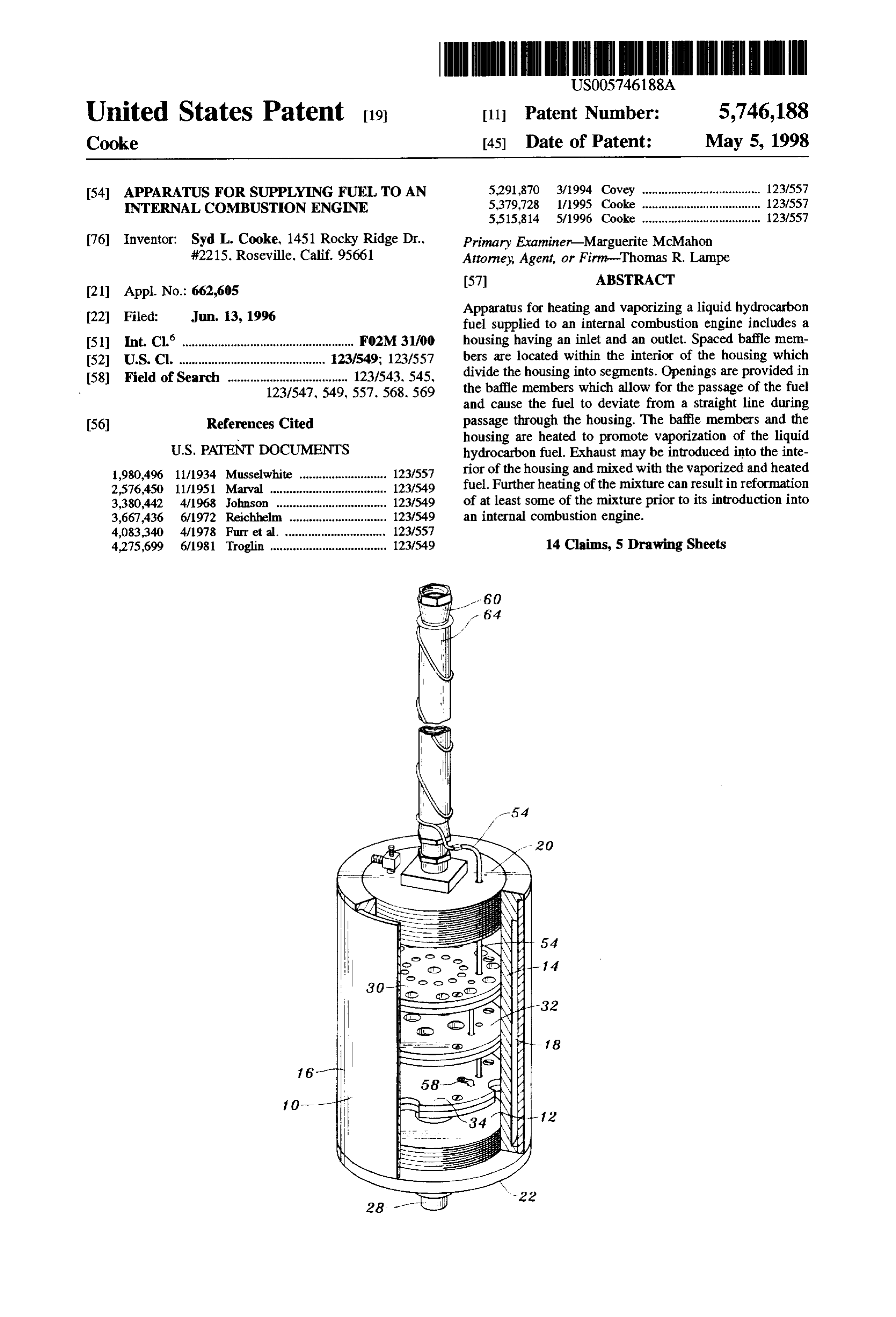
Apparatus for heating and vaporizing a liquid hydrocarbon 22 Filed: Jun. 13, 1996 fuel supplied to an internal combustion engine includes a (51 int. Cl. ............................... FO2M 31/00 housing having an inlet and an outlet. Spaced baffle mem 52 U.S. Cl. ........................................... 123/549; 123/557 bers are located within the interior of the housing which 58) Field of Search ..................................... 123/543, 545, divide the housing into segments. Openings are provided in 123/547, 549, 557, 568, 569 the baffle members which allow for the passage of the fuel and cause the fuel to deviate from a straight line during (56) References Cited passage through the housing. The baffle members and the housing are heated to promote vaporization of the liquid
1980,496 11/1934 Musselwhite ........................... 123/557 rior of the housing and mixed with the vaporized and heated 2,576,450 11/1951 Marval ........... . . 123/549 fuel. Further heating of the mixture can result in reformation 3,380,442 4/1968 Johnson ..... . . 123/549 of at least some of the mixture prior to its introduction into 3,667,436 6/1972 Reichhelm .............................. 123/549 an internal combustion engine.
4,083,340 4/1978 Furr et al. ...... ... 123/557 4,275,699 6/1981 Troglin .................................... 123/549 14 Claims, 5 Drawing Sheets
Page 2
Drawing sheet — no readable text.
Page 3
Drawing sheet — no readable text.
Page 4
Drawing sheet — no readable text.
Page 5
Drawing sheet — no readable text.
Page 6
Drawing sheet — no readable text.
Page 7
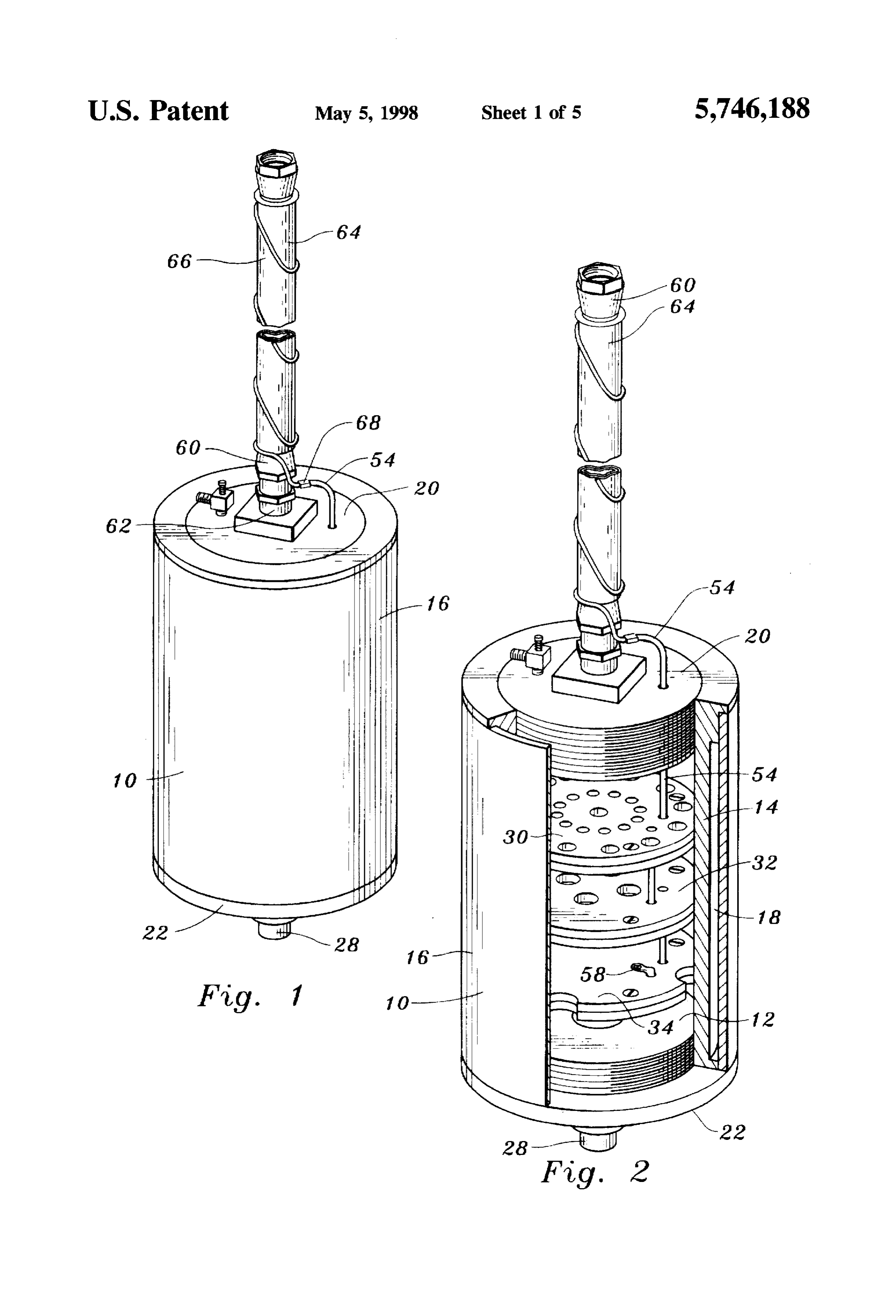
APPARATUS FOR SUPPLYNG FUEL TO AN BRIEF DESCRIPTION OF DRAWINGS INTERNAL COMBUSTON ENGINE FIG. 1 is a perspective view of apparatus constructed in TECHNICAL FIELD accordance with the teachings of the present invention; FIG. 2 is a slightly enlarged perspective view of the
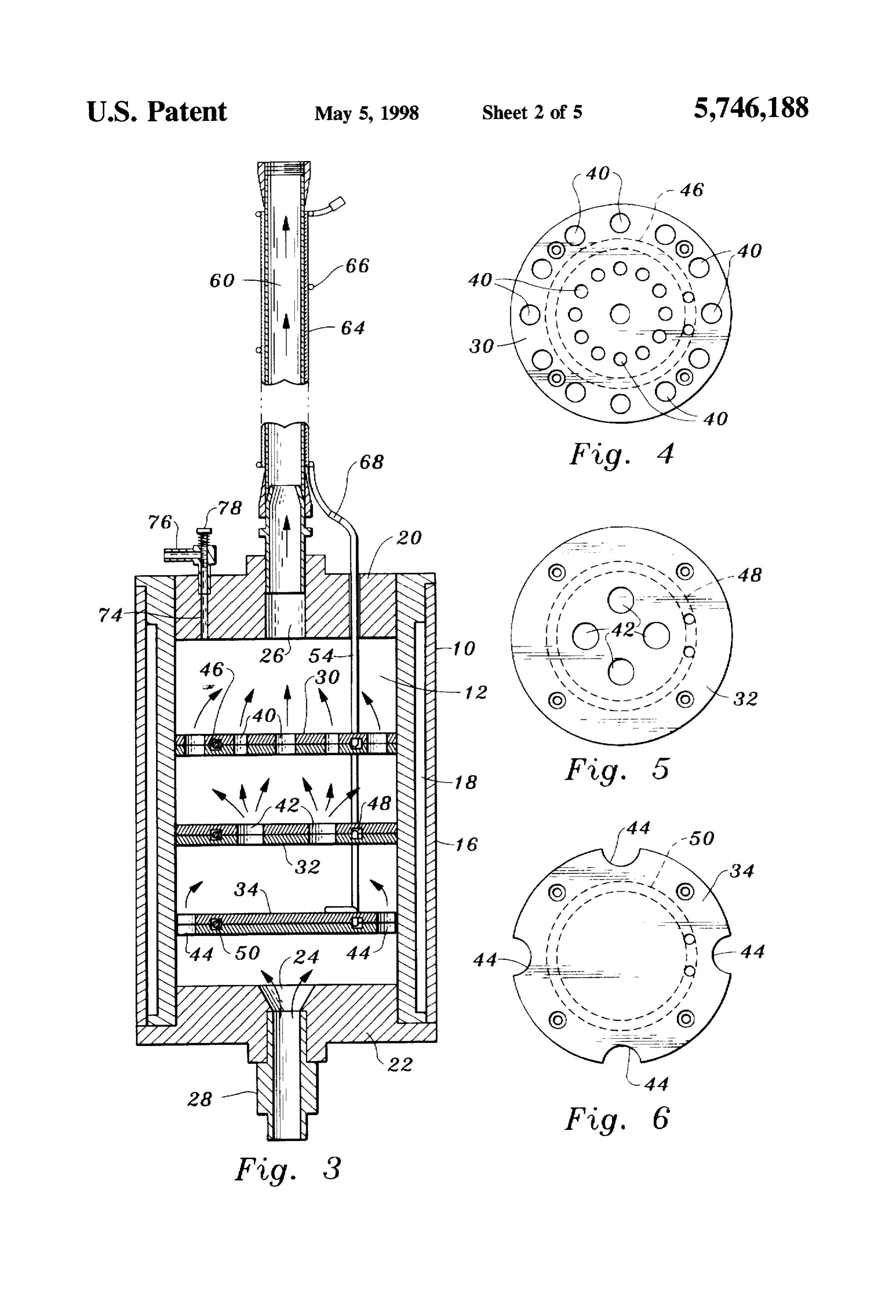
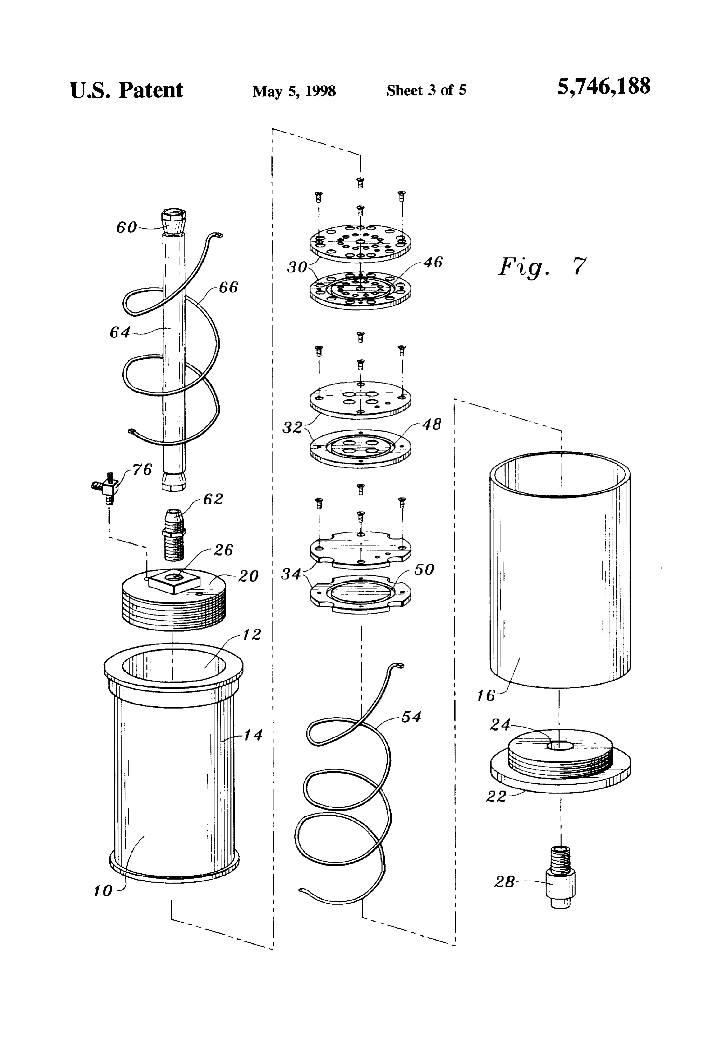
This invention relates to apparatus for use with an internal 5 apparatus combustion engine for supplying fuel to the internal com interior with a portion thereof broken away to disclose bustion engine. More particularly, the apparatus is utilized to components thereof; heat, vaporize and otherwise treat liquid hydrocarbon fuel to FIG. 3 is a frontal cross-sectional view of the apparatus a promote engine efficiency and lower emissions. portion thereof broken away;
10 FIGS. 4, 5 and 6 are plan views of three baffle members
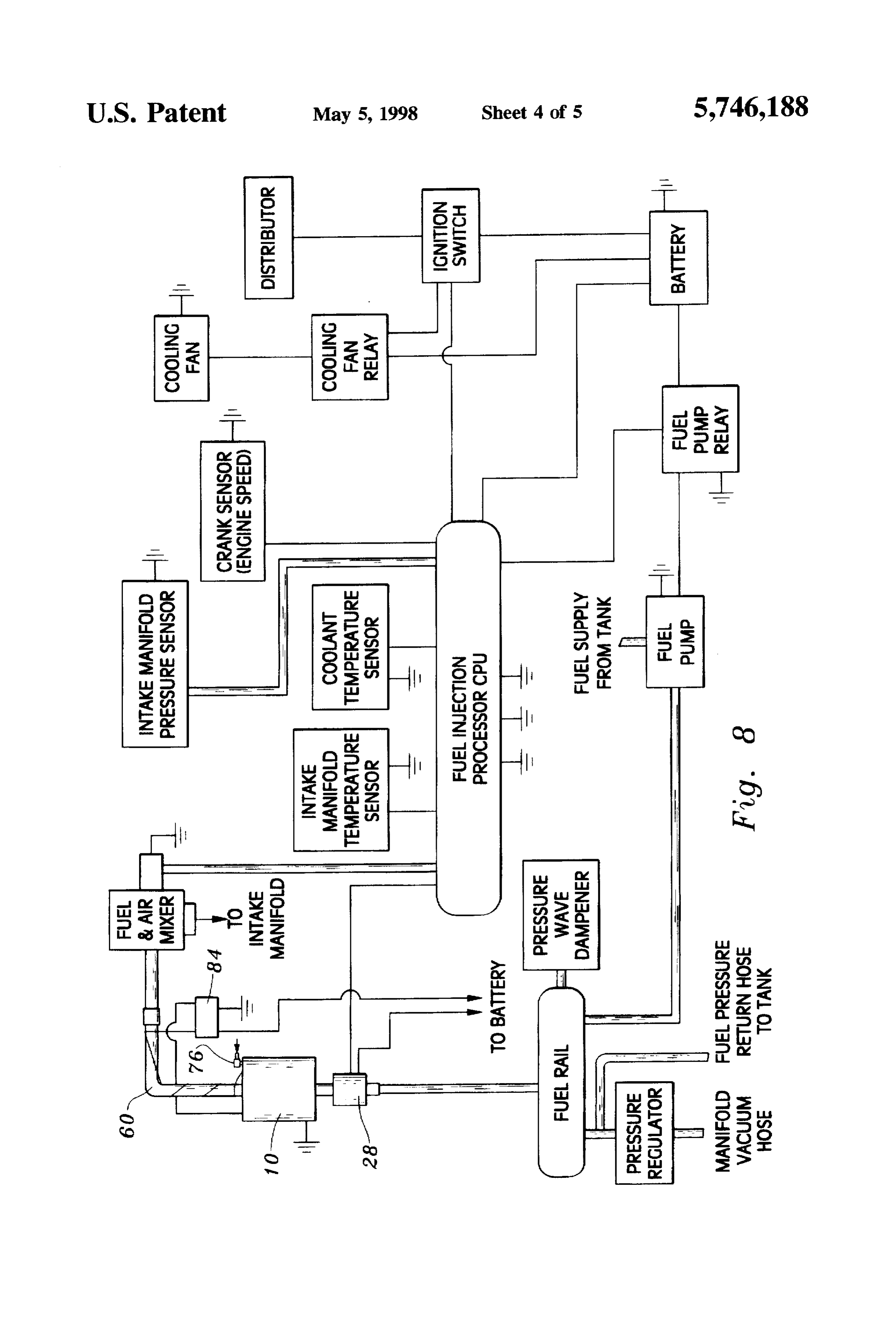
BACKGROUND ART having differing configurations employed in the apparatus; It is known that the heating and vaporization of gasoline FIG. 7 is an exploded view of the apparatus; and other types of liquid hydrocarbon fuels can increase FIG. 8 is a schematic diagram illustrating the apparatus of efficiency or improve the performance of internal combus the present invention in combination with related structure tion engines. Arrangements for accomplishing such objec in a representative operating environment; and
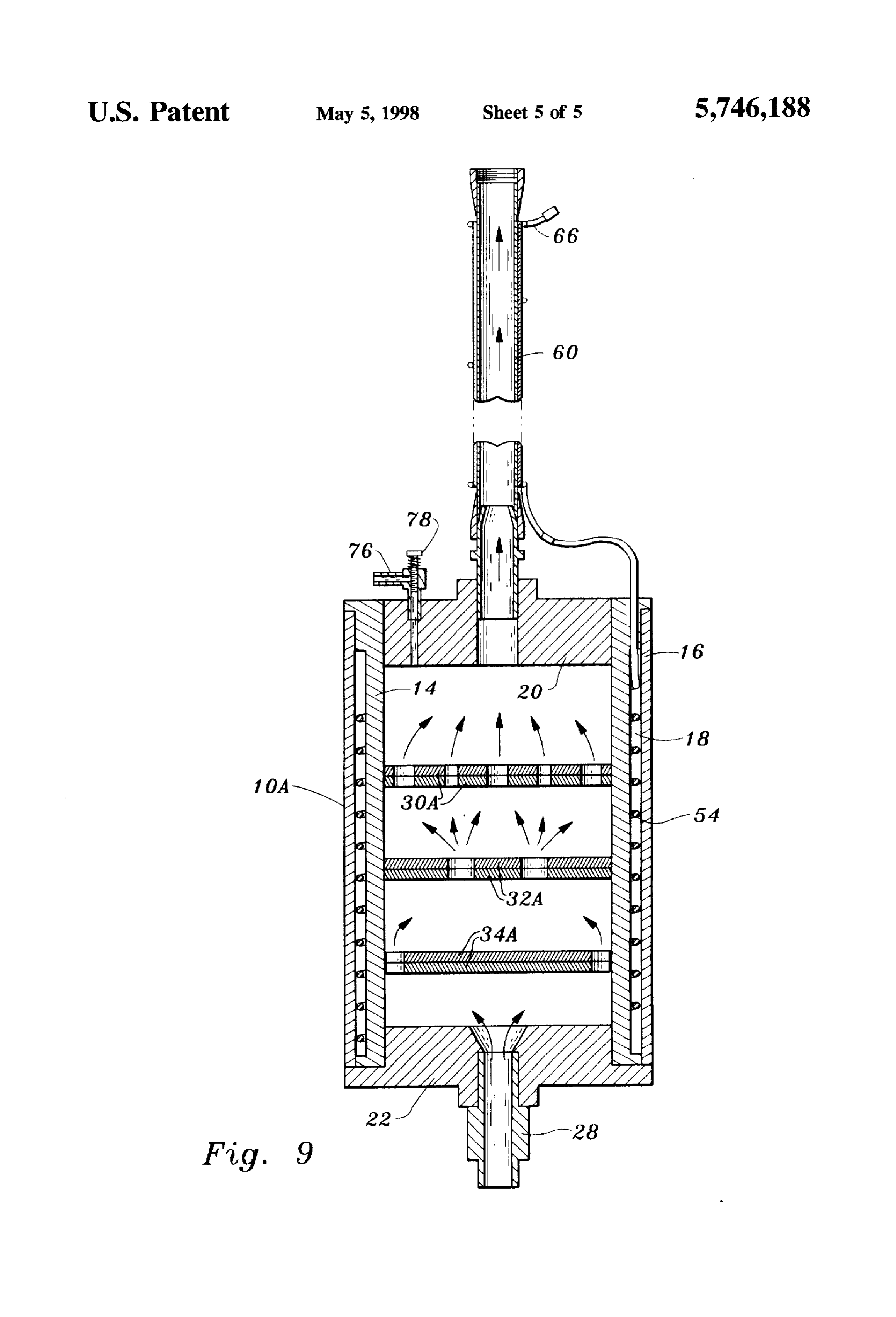
tives are generally characterized by their complexity and FIG. 9 is a view similar to FIG. 3 but illustrating an relatively high expense. Reliability is also a problem and alternate form of the apparatus.
devices of this type have not found widespread acceptance for these and other reasons. BEST MODE FOR CARRYING OUT THE My U.S. Pat. No. 5,515,814, issued May 14, 1996, INVENTION discloses an apparatus and method for supplying fuel to an internal combustion engine. My U.S. Pat. No. 5,379,728, Referring now to FIGS. 1-7 of the drawings, apparatus issued Jan. 10, 1995, also discloses an apparatus and method constructed in accordance with the teachings of the present for supplying fuel to an internal combustion engine. In the 25 invention includes a housing 10 defining a housing interior systems disclosed in these patents a liquid hydrocarbon fuel 12. The housing 10 includes a cylindrically shaped inner is injected into a fuel chamber to form a mixture of vapor sleeve 14 formed of a suitable heat transmitting material, ized liquid hydrocarbon fuel and heated exhaust gases. The such as aluminum, and an outer protective layer 16 formed mixture is passed through a passageway and further heated of a suitable heat insulating material such as ceramic mate by non-contacting exhaust gases from the internal combus 30 rial. An annular space 18 is defined by the inner and outer tion engine to reform at least a portion of the mixture of sleeves.
vaporized liquid hydrocarbon fuel and heated exhaust gases Housing 10 also includes two end caps 20, 22 which are in the passageway. threadedly engaged with the inner sleeve 14 or otherwise
DISCLOSURE OF INVENTION
secured thereto. End cap 22 defines an inlet 24 and end cap 20 defines an outlet 26. The end caps may be formed of any
The apparatus of the present invention is characterized by 35 suitable material such as aluminum. At least one fuel injector its relative simplicity of construction and compactness. No 28 is secured to end cap 22 and provides for the injection of catalysts are required for its operation. The apparatus is gasoline or other liquid hydrocarbon fuels into the housing further characterized by its high reliability during operation. interior 12.
Employment of the apparatus will serve to lower emissions Spaced baffle members 30, 32, 34 are located within the and the apparatus may be readily installed in association housing interior 12 and divide the housing interior into with virtually any type of internal combustion engine, housing interior segments. These baffle members define including those of cars and other vehicles. openings allowing passage of the liquid hydrocarbon fuel The apparatus of the present invention is for use with an between adjacent housing interior segments as the liquid internal combustion engine and is for supplying fuel to the 45 hydrocarbon fuel passes through the housing interior 12 internal combustion engine. from the inlet 24 to the outlet 26. The openings in baffle The apparatus includes housing means defining a housing member 30 are designated by reference numeral 40, the interior, the housing means defining an inlet and an outlet. openings in baffle member 32 by reference numeral 42, and The inlet and the outlet are spaced from one another and the openings in baffle member 34 by reference numeral 44. communicate with the housing interior. The inlet is for 50 The baffle members are constructed of suitable heat receiving liquid hydrocarbon fuel and introducing the liquid transmitting material such as aluminum or copper and, in the hydrocarbon fuel into the housing interior. arrangement illustrated, each of the baffle members has a A plurality of spaced baffle members are located within plate-like configuration and is comprised of two plate mem the housing interior. The baffle members divide the housing bers secured together in registry by screws or other mechani interior into housing interior segments and each of the baffle 55 cal fasteners. The peripheral edges of the baffle members are members defines at least one opening allowing passage of in engagement with inner sleeve 14 of the housing and fixed the liquid hydrocarbon fuel between adjacent housing inte in place by any suitable expedient.
rior segments as the liquid hydrocarbon fuel passes through Baffle member 30 defines a generally circular channel or the housing interior from the inlet to the outlet. void 46. Baffle member 32 defines a generally circular Heating means is provided for heating the baffle members. shaped channel or void 48. And baffle member 34 defines a The baffle members heated by the heating means heat and generally circular-shaped channel or void 50. promote the vaporization of the liquid hydrocarbon fuel as Extending through an opening in end cap 20 is a resis the liquid hydrocarbon fuel passes through the housing tance heating element 54 comprised of a wire formed of interior from the inlet to the outlet. nickel chromium or other suitable material surrounded by an Other features, advantages, and objects of the present 65 electrical insulating, heat transmissive layer formed of a invention will become apparent with reference to the fol silicone substance or other suitable material. The heating lowing description and accompanying drawings. element 54 extends between the baffle members and is
Page 8
looped as shown so that portions thereof are positioned in Suffice it to say that the structure includes a CPU. Inputs the circular-shaped channels of the baffle members. At the to the CPU include those from a crank sensor, an intake bottom end thereof wire heating element 54 is secured to manifold pressure sensor, a throttle position sensor, an baffle member 34 by screw 58. intake manifold temperature sensor and a coolant tempera It will be appreciated that when the heating element 54 is ture SensOr.
heated, the baffle members 30, 32, 34 will be heated also. The CPU is suitably programmed so that the crank sensor Furthermore, the inner sleeve 14 of the housing will be input will function to turn the fuel injector 28 on and off. As heated by the baffle members which, of course, are in indicated above, more than one injector may be employed engagement therewith. when practicing this invention. The function of the intake Secured to and projecting from end cap 20 is a tubular 10 manifold pressure sensor is to regulate how long the fuel shaped conduit 60 defining a conduit interior. In the arrange injector stays open. The throttle position sensor performs a ment illustrated, a threaded nipple 62 is employed to secure similar function but to a lesser degree. The intake manifold the conduit to the end cap 20; however, any suitable expe temperature sensor and the coolant temperature sensor dient may be employed for this purpose. Conduit 60 is inputs provide for slight mixture modification. constructed of a suitable heat transmissive material such as 15 copper and has an electrically insulating, heat transmitting theThe fuel outputs from the CPU go to the fuel injector through injector drives.
layer 64 formed of a silicone substance or other suitable The fuel pump relay is powered by a battery and provides material wrapped thereabout. Wrapped about conduit 60 and sleeve 64 is a resistance heating wire 66 formed of nickel power to the fuel pump. The relay is activated by the ignition chromium or other suitable material. Wire 66 extends sub 20 switch. The fuel pump is fed fuel from the fuel tank and in turn provides available pressure (e.g. 70 PSI) to the fuel rail.
stantially the full length of conduit 60 and at one end thereof The is connected to wire 54 by a electrical connector 68. Thus. injector fuel rail then regulates the fuel supply to the fuel a closed electrical circuit incorporating wires 54, 66 will of the fuel at a lesser pressure (e.g. 30 PSI) and returns the rest serve to heat both wires simultaneously. to the fuel tank through a return hose. The fuel FIG. 3 illustrates with arrows the flow of liquid hydro 25 injector 28 injects the fuel into the apparatus of the present carbon fuel through housing 10 during operation of the invention clean which can be utilized to reform the fuel into a useable fuel and supply the reformed fuel to a fuel and apparatus. With additional reference to FIG. 8, the fuel is air mixer and/or injectors which in turn supplies the correct received from a conventional fuel rail and introduced into the interior of the housing through inlet 24. The liquid mixture to the engine. The apparatus may also be employed simply to provide heated vaporized fuel to the engine. A hydrocarbon fuel, by necessity, must deviate from a straight 30 thermostat path as it passes between the inlet and outlet. As a matter of temperatures84appliedis employed in the system to control the by wires 54,66 during operation of the fact, the fuel, which must pass through the openings in the system.
baffle members, follows a number of relatively serpentine paths as the fuel makes its way to the outlet 26. During such FIG. 9 illustrates an alternative embodiment of the appa movement the fuel contacts the heated baffle members and 35 ratus wherein elongated heating element 54 is located in the the heated inner sleeve 14 of the housing. The fuel is thus annular space 18 of the housing and wrapped about inner agitated and heated simultaneously. This results in vapor sleeve 14. The wire is not actually positioned in the housing ization of the fuel by the time it reaches outlet 26. interior nor in direct engagement with baffle members 30, An inlet opening 74 is formed in end cap 20 and a fitting 32, 34. Instead, heat is supplied to the baffle members by 76 defining a fitting passageway is threadedly engaged or being ofdirectly virtue their engagement with the inner sleeve 14, the latter heated by the wire 54. As with the first otherwise secured to the end cap 20 so that the fitting embodiment described above, the heating element 54 passageway is in communication with inlet opening 74. A includes not only the inner electrical resistance element or needle valve 78 is employed to control flow through the wire per se but also an electrically insulating sleeve which fitting passageway and inlet opening 74. Through suitable allows for the transmission of heat from the wire per se to conduit means (not shown) the passageway of fitting 76 may 45 the receive exhaust gases produced by an internal combustion adjoining structure.
engine (not shown) with which the apparatus is operatively I claim:
associated. These exhaust gases are mixed with the heated for1.supplying
Apparatus for use with an internal combustion engine fuel to said internal combustion engine, said and vaporized liquid hydrocarbon fuel within housing inte apparatus comprising, in combination: rior 12 just prior to the heated and vaporized fuel exiting 50 outlet 26 into conduit 60. housing means defining a housing interior, said housing As stated above, conduit 60 is continuously heated by means defining an inlet and an outlet, said inlet and said wire 66. This will result in heating of the mixture of outlet being spaced from one another and communi vaporized liquid hydrocarbon fuel and heated exhaust gases cating with said housing interior, said inlet for receiv within conduit 60. Sufficient heating of the mixture within 55 ing liquid hydrocarbon fuel and introducing said liquid the confines of the conduit will cause reaction of the mixture hydrocarbon fuel into said housing interior; with resultant combustion and reformation of at least a a plurality of spaced baffle members located within said portion thereof to a clean usable fuel in the manner sug housing interior, said baffle members dividing said gested by my U.S. Pat. No. 5.515.814, issued May 14, 1996. housing interior into housing interior segments and The mixture exiting the conduit 60 may be directed to the each of said baffle members defining at least one internal combustion engine from which the exhaust gases opening allowing passage of said liquid hydrocarbon were received for complete combustion. fuel between adjacent housing interior segments as said FIG. 8 shows the apparatus in a typical operating envi liquid hydrocarbon fuel passes through said housing ronment with other structure. Since such structure is known interior from said inlet to said outlet; in the internal combustion engine and fuel injector art and 65 heating means for heating said baffle members, said baffle forms no part of the present invention per se it will not be members heated by said heating means heating and described in detail. promoting the vaporization of said liquid hydrocarbon
Page 9
fuel as said liquid hydrocarbon fuel passes through said 8. The apparatus according to claim 7 wherein at least housing interior from said inlet to said outlet; and some of said baffle members are plates including two plate members secured together and defining at least one of said a conduit leading from said housing means outlet and channels, defining a conduit interior communicating with said disposed betweensaid elongated electrical resistance heater being housing interior, said heating means including an elon said two plate members. 9. The apparatus according to claim 2 wherein said baffle gated electrical resistance element operatively associ members are in engagement with said housing wall for ated with said conduit and extending along said conduit providing conductive heat transfer between said baffle mem to heat said conduit and further heat the liquid hydro bers and said housing wall.
carbon fuel after the liquid hydrocarbon fuel has exited 10. The apparatus according to claim 5 wherein said said housing interior from said outlet. housing wall defines an annular space accommodating said 2. The apparatus according to claim 1 wherein said elongated electrical resistance heater means. housing includes a housing wall extending around said baffle 11. The apparatus according to claim 1 wherein openings members, said heating means cooperable with said housing of adjacent baffle members are out of registry whereby wall to heat said housing wall. liquid hydrocarbon fuel passing through said inlet to said 3. The apparatus according to claim 1 wherein said 15 outlet deviates from a straight path and is agitated by heating means includes electrical resistance heater means impacting said baffle members.
positioned in said housing interior and located adjacent to 12. The apparatus according to claim 1 wherein said said baffle members. housing means additionally comprises an inlet opening for 4. The apparatus according to claim 2 wherein said introducing internal combustion engine exhaust into said heating means includes electrical resistance heater means housing interior to mix with the liquid hydrocarbon fuel extending along and closely adjacent to said housing wall. passing through said housing interior from said inlet to said 5. The apparatus according to claim 4 wherein said outlet.
electrical resistance heater means is elongated and extends 13. The apparatus according to claim 12 additionally about the periphery of said housing wall. comprising flow control means for controlling the flow of 6. The apparatus according to claim3 wherein said baffle 25 internal combustion engine exhaust into said housing inte members define voids, said electrical resistance heater rior through said inlet opening. means positioned in said voids. 14. The apparatus according to claim 3 additionally 7. The apparatus according to claim 6 wherein said voids comprising thermostat means for controlling the operation comprise channels, said electrical resistance heater means of said electrical resistance heater means. being elongated, positioned in said channels and extending 30 sk :k e xk sk between said baffle members.
Provenance
- Collection
- Cited prior art
- Original PDF
- patentimages.storage.googleapis.com →
- Filed
- 1996-06-13
- Pages
- 9
- Method
- pdftotext (the PDF's own text layer) + pdftoppm 300dpi page scans
- Source
- Google Patents bibliographic record
- Granted
- 1998-05-05
- Inventors
- Syd L. Cooke; NATURAL RESOURCES FOUNDATION
- Transcribed from
- patentimages.storage.googleapis.com →