patent · US4384611
Heat exchanger
24 May 1983
Page 1 — bibliographic record
United
Fung
States Patent
(19) 11) 4,384,611
(54) HEAT EXCHANGER 3,552,488 1/1971 Grill .................................... 165/66 3,827,343 8/1974 Darm ... ... 65/166 75) Inventor: James Y. Fung, Closter, N.J. 3,912,004 10/1975 Darm ....... ... 165/166 (73) Assignee: HXK Inc., Bogota, N.J. 4,116,271 9/1978 Lepeleire ............................ 165/166 (21) Appl. No.: 201,600 Primary Examiner-William R. Cline Assistant Examiner-Theophil W. Streule, Jr.
22 Filed: Oct. 28, 1980 Attorney, Agent, or Firm-S. C. Yuter Related U.S. Application Data (57) ABSTRACT 63 Continuation of Ser. No. 905,789, May 15, 1978, aban A heat exchanger core is formed from a single foil strip doned. folded into successive U-bends to define alternate fluid passages, with even-numbered passages being for hot 51) Int. Cl. ... ... F28F 3/00; F28F 3/08 fluid and odd-numbered passages being for cold fluid. 52 U.S. C. .................................................... 165/166 The folded foil thus defines three walls of each passage 58) Field of Search ........................ 165/157, 166, 167 with the remaining fourth side open. Top and bottom (56) References Cited plates cover and close the open sides of all the hot and
remain open; the ends of other passages are selectively l,548,159 8/1925 Murray ............................... 165/166 closed by pinching together the ends of adjacent foil 1,966,133 7/1934 Pieper ... . . 165/166 walls which define the passages. A pre-formed end plate 2,321,110 6/1943 Shipman ..... ... 165/166 has apertures between deformable ribs; the apertures 2,361,691 10/1944 Jendrassik ........................... 65/166 are aligned with the ends of open passages, and the ribs 2,462,421 2/1949 Pitt ...................................... 165/166 2,877,000 3/1959. Person ................................. 165/166 overlie and are joined with the pinched ends of the 2,945,680 7/1960 Slemmons ........................... 165/166 closed passages.
3,451,474 6/1969 Cox ............ ... 165/66 3,545,062 12/1970 Cox ..................................... 165/66 13 Claims, 37 Drawing Figures
Page 2
Drawing sheet — no readable text.
Page 3
Drawing sheet — no readable text.
Page 4
Drawing sheet — no readable text.
Page 5
Drawing sheet — no readable text.
Page 6
Drawing sheet — no readable text.
Page 7
Drawing sheet — no readable text.
Page 8
Drawing sheet — no readable text.
Page 9
Drawing sheet — no readable text.
Page 10
Drawing sheet — no readable text.
Page 11
SERIESH
sOO
Construction: 16 ga. aluminum casing .008 thick heat transfer media
SERIES X
Construction: 6 ga. aluminum casing OO8 thick heat transfer media
SERESK
Construction: 16 ga. aluminum casing OO8 thick heat transfer media
Page 12
Balance Flow Unbalance. Flow
600 700 800 900 OOC .6 8 1.0 .2 4. s Welocity. ft/min Series X-1 SCFM Supp 2298 3064. 38.33 Flow Ratio St. Exhaust SCFM Supply
Formula to Convert Velocity to CFM Example: Given 30,000 CFM, 8" W.C. from pressure drop velocity curve g 1000 ft/min pressure drop.8"
Seriesh & K CFM = velocity x 1.27 X-1 a 3833 CFM/module at 1000 ft/min Series x. 8, 2 CFM is velocity x 3.83 30,000 is 7. les. dul X-3 4 CFM = velocity x 2.55 38.33 7.8 nodules. use 8 modules
Engineering Formula for Heat Recovery Calculation
460 --T T T. F.T. -- Ea (T-T) - use E for balance flow system
SCFM Supply T scFM. s
P.D. =: STD Pressure Drop - "C" see chart below at given temperature and altitude
Altitude in Feet Above Sea level
Average
Air
in inches
Temperature
EEEEEEE
964 930 896 TB64 832 801
5o 869 .723
64s 624 604 58o 55 631 Goa 586 565 T 544 524
Page 13
will extend across and cover the open upward sides of
HEAT EXCHANGER the first set of passages, and a similar bottom plate will cover and close the second set of downward facing
This is a continuation of application Ser. No. 905,789, passages. - filed May 15, 1978 now abandoned. In preferred embodiments supplemental side walls BACKGROUND OF THE INVENTION are added to improve stability and to provide means for mounting the heat exchanger to associated structures.
This invention is in the field of heat exchangers and Finally there is the new end cap structure for coopera more particularly heat exchangers for transmitting ther tion with the open ends of the various passageways. In mal energy from one moving fluid to another with O order to define specific flow paths of the fluid through specific application for gaseous fluid mediums. Typi the passages, it is necessary to block off portions of the cally heat exchangers comprise a plurality of adjacent ends of each passage, to thereby direct the fluid flow to passageways with relatively hot and relatively cold and through the unblocked portions. For example, if fluids in adjacent passages for facilitating the transfer of there are not blocked portions of the ends of the pas thermal energy from the hot fluid through the passage sageways, and the heat exchanger is designed for coun walls to the cold fluid. It is common for the hot and cold terflow operation, then hot fluid and cold fluid will fluids to flow in opposite directions or in perpendicular flow in opposite directions and will essentially fill the directions designated counter-flow and cross-flow re passageways and will enter and exit essentially through spectively; also in some cases the fluids flow in the same the entire open portions of the various ends of these direction designated parallel-flow. 20 passages. By selectively and partially blocking the ends In the various apparatus there are a variety of design of these passages, a great variety of fluid flow paths parameters which are selected in particular combina within the general concept of counter-flow may be tions to achieve various objectives, while necessarily established.
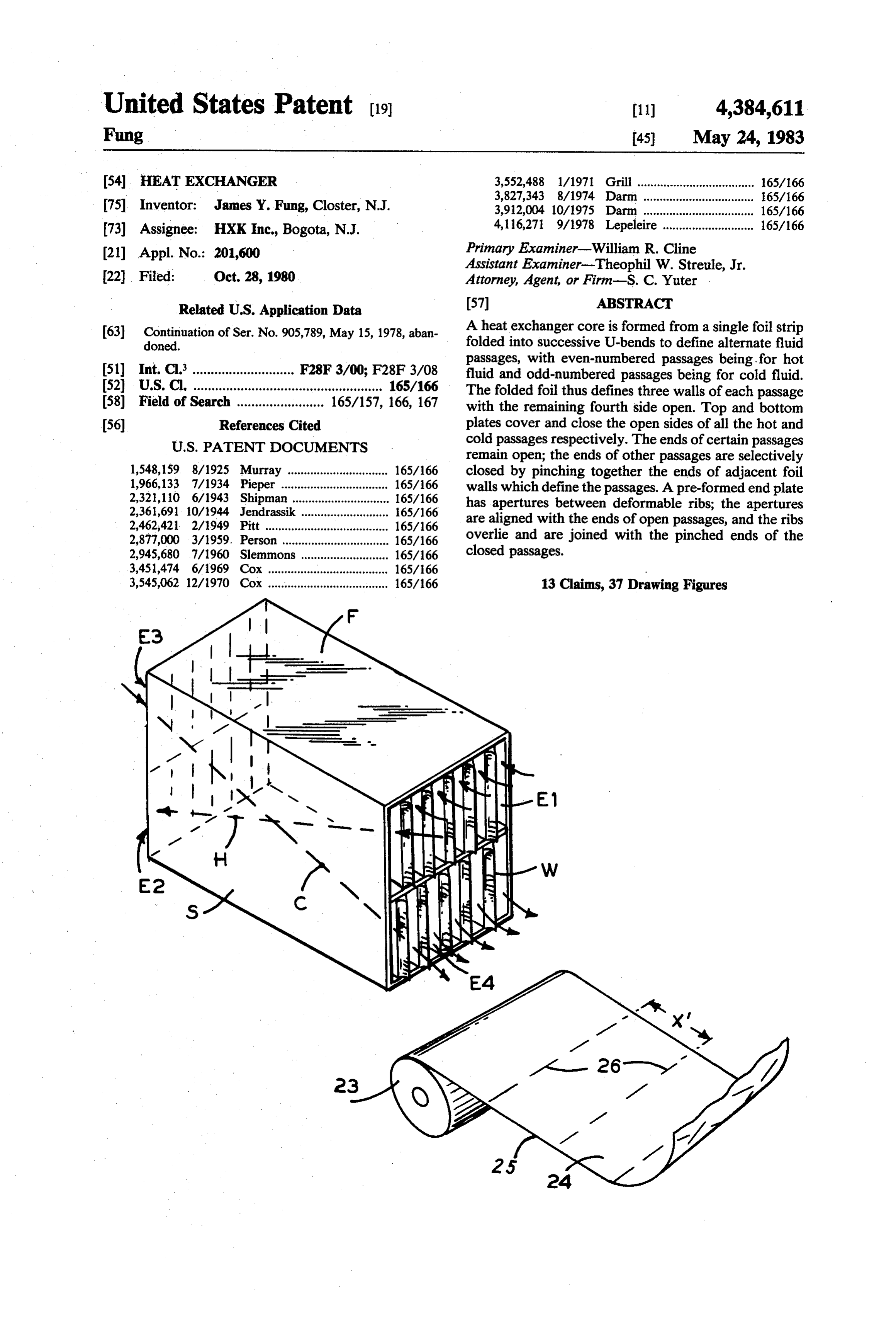
sacrificing other factors, and in effect trading off one The present invention uses three principal variations advantage for a different disadvantage. Certain of the 25 of the basic counter-flow flow pattern, which are desig most relevant parameters are thermal efficiency, pres nated Series X, Series H, and Series K and combinations sure drop of the fluid through the passageway, manu thereof. In Series X for example, if the apparatus is facturing cost, rate of fluid flow through the device, and oriented such that the passages extend horizontally and size and weight of the heat exchanger. Additional fea the hot fluid flows from left to right, such hot fluid in a tures that are relatively well known in the heat ex 30 Series X device enters at the upper portion at the left changer art include the use of a plurality of separate and flows generally downward to the bottom portion at plates or sheets to define and separate the fluid passages, the right; meanwhile the cold fluid enters at the upper and sealing means for joining the various edges of these portion at the right and flows generally downward to partitions to the housing and preventing leakage of the the lower portion at the left. This produces an X-shaped fluid between chambers or from the overall apparatus. 35 flow path between the hot and cold fluids which results A still further feature of heat exchangers is the require in excellent thermal efficiency and provides a very ment of some type of manifold inlet or outlet whereby convenient manner for separating the hot and cold flu hot fluids may be directed to specific passages, while ids as will be explained below.
cold fluids are directed to the various alternate passages If there were no blockages and the hot and cold fluid in between the hot passages. flows at one end for example were all at the same hori Assembly techniques for typical heat exchangers zontal and adjacent level, there could be a considerable include welding, brazing, bonding, crimping, and the problem in separating each hot flow from all the adja use of fasteners. In substantially all situations there is the cent cold flows, and combining all the hot flows with complication of holding together in precise spaced rela out intermixing them with any cold flows. However, in tionship a great many individual pieces so that the mul 45 the Series X design, all the hot flows enter at the upper titude of passageways can be defined in a structure portion of one end, while all the cold flows are dis which is otherwise semi-rigid as a whole, and wherein charged from the lower portion of the same end. At the there is sufficient strength internally to prevent the upper left portion where the hot flows enter into alter passageways or walls forming said passages from buck nate passageways, the spaces between these passage ling or warping due to the heat extremes experienced on 50 ways are blocked so that there is no interference from the opposite sides of partition walls and throughout the or with the cold fluid. Correspondingly, on the right apparatus. side where hot flow passages are open for discharge, the SUMMARY OF THE INVENTON spaces between these passages are blocked so that there is not interference with or from the entering cold flow.
This invention is a new heat exchanger preferably for 55 The ends of these passages are defined by the U-shaped counter-flow heat exchange of gaseous fluid mediums. edges of the foil. To block a flow path, the adjacent The fluid flow passages are established by a new heat edges defining the path are pinched and sealed together exchanger core which is a construction formed by a in certain preferred embodiments of this invention. To continuous foil strip formed into successive U-bends, facilitate this blocking there is an end cap, which in one thereby providing a plurality of foil partitions which embodiment is initially a flat sheet with apertures corre define adjacent flow passages. When the resulting struc sponding to the selected passageways; between each ture is oriented with these partition walls extending two apertures, there is provided a thin rib which is generally vertically, each passage will be defined by concave or V-shaped in the direction of the pinched two adjacent, generally vertical walls, one generally portions of the end edges of the partitions. In assembly horizontal wall, and one open side; therefore a first set 65 of a heat exchange core according to this invention, the of spaced-apart passages will have their open sides fac concave face of each rib is placed adjacent to the ing upward, and a second series of interspersed passages pinched end of a foil passage, and the rib and pinched will have their open sides facing downward. A top plate end are crimped or pinched together which serves dual
Page 14
purposes. First, this closes and seals selected ends of contamination and essentially no leakage between coun fluid passages; second, the one piece end plate contacts ter-flow passages, and the resulting design will be com and is secured to all the partitions, and thus integrates pact and lightweight and may in fact be modular so that and strengthens the assembly. With this kind of struc individual units can be easily stacked or aligned to cre ture a single end cap component can cover the entire ate units of varying sizes. Furthermore the dimensions end of a heat exchange core, and simultaneously when of any particular heat exchanger can be easily varied by assembled, seal all the blocked passages while cooperat simply beginning with a longer sheet of foil and creating ing in the definition of all the open passages. in this sheet additional folds and partitions with corre In the manufacture of this new heat exchanger core spondingly larger front plates and end plates. In opera an initial step is die-forming the surface of the foil strip 10 to have a plurality of parallel bend lines perpendicular tion which such a sheet is continuously formed and folded greatly reduces fabrication costs.
to the length of the strip and spaced apart to define the partitions. The die-forming also establishes a pattern in one-stepend
The and plates may be die-formed in an essentially very efficient process; however, it is also the foil surface of diagonal and axial stiffening ribs and possible to construct end plates by using a welded or generally circular spacer dimples, all of which consti 15 brazed frame and individually welded or brazed ribs. tute projections from the upper or lower surface of the This latter version is more costly as regards manufac foil. Each partition has essentially the same pattern, ture of each specific end plate, however it eliminates the except that in each two adjacent partitions correspond high initial expense for a suitable die. Also by using the ing spacer dimples extend in the same direction and corresponding stiffening ribs extend in opposite direc 20 die-formed end pieces the welding steps are eliminated, tions. When the foil strip with these patterns is folded to which not only reduces labor cost, but eliminates the heat which tends to warp and otherwise deform the define adjacent partitions, corresponding spacers will product.
extend toward each other for spacing the partitions problems Finally the all metal construction eliminates of toxicity that otherwise occurs when using apart, and corresponding stiffening ribs will extend in epoxy, resins, or other sealants, as is generally necessary the same direction so that the distance between these rib 25 surfaces remains essentially the same as the distance in The the prior art.
heat exchange devices of this invention may be between the flat portions of the partitions.
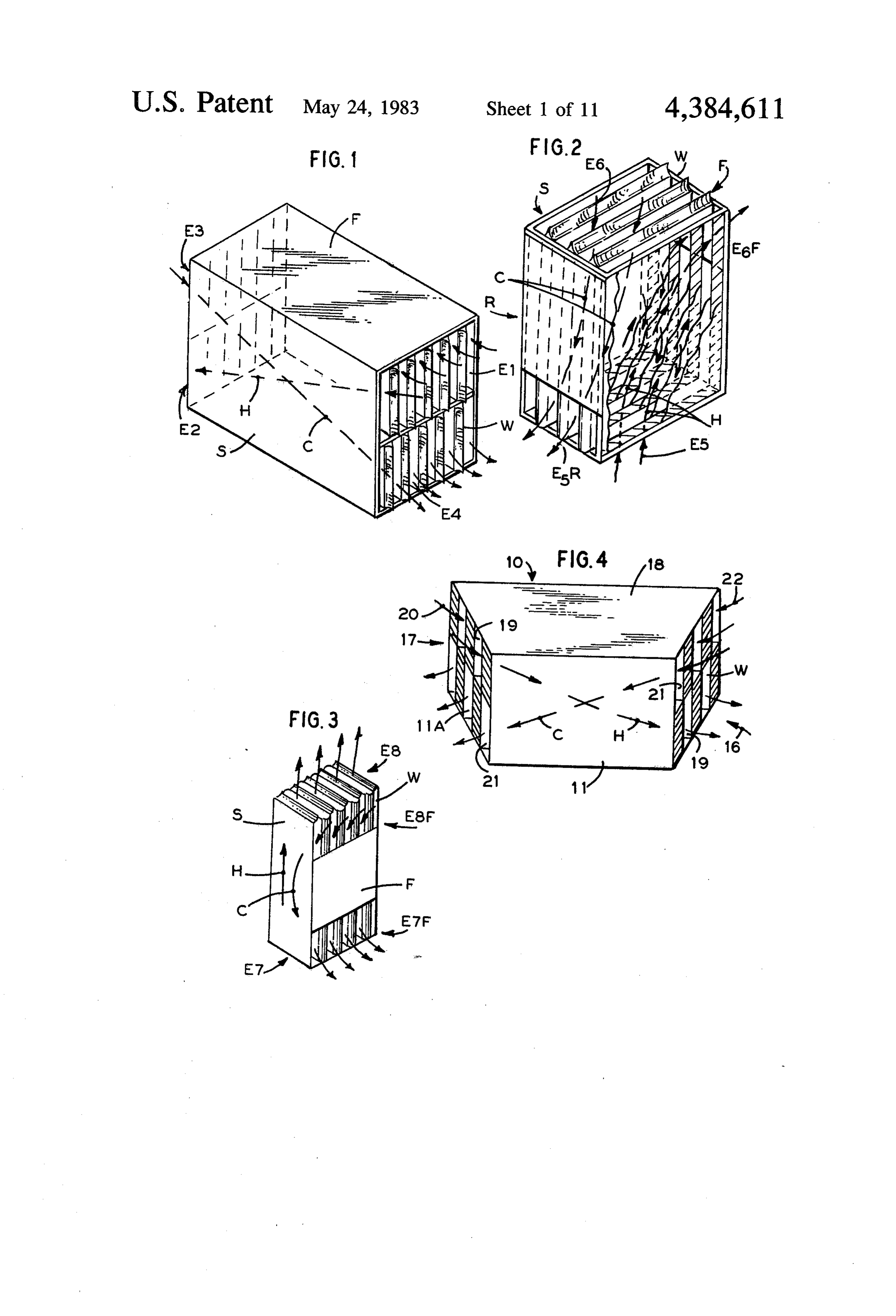
With the heat exchanger as described there is essen many used with air or a variety of different fluids and for tially no requirement for any sealing material such as different purposes; it has been determined that resin or cement or welding or brazing to prevent leak 30 these devices are particularly useful in powered ventila age of the heat exchange fluids from the heat exchanger tion systems where exhaust air heat recovery is of im to the outside, or between hot and cold gas passages. portance. The invention disclosure herein includes the This reduces both cost of manufacture and weight of basic structure and method of making new heat ex the finished product. As indicated the rib structure of changers; however, further details such as welding, the end plate and assembly of this plate with the parti 35 cutting, sealing, riveting, crimping, etc. can be found in tions provides sufficient rigidity for this heat exchanger standard practice and prior art literature. to withstand extreme temperature and pressure differ BRIEF DESCRIPTION OF THE DRAWINGS entials that develop. The die-formed, essentially one piece continuously bent core also is very economical FIG. 1 is a perspective and schematic view of a Ser and relatively easy to make, and permits an automated ies-X heat exchanger of this invention; operation which can be very accurate and permit very FIG. 2 is a perspective and schematic view of a Ser fast and high volume production. ies-H heat exchanger thereof; Another important advantage of the invention is the FIG. 3 is a perspective and schematic view of a Ser fact that by simple removal of front and rear covers, ies-K heat exchanger thereof;
substantially the entire interior of the passageways are 45 FIG. 4 is an expanded and intentionally distorted exposed for inspection and cleaning. The stiffening ribs perspective view of the Series-X heat exchanger of and spacer projections will partially interfere with a FIG. 1 showing both ends of the apparatus simulta clear view to every square inch of the interior surfaces, neously;
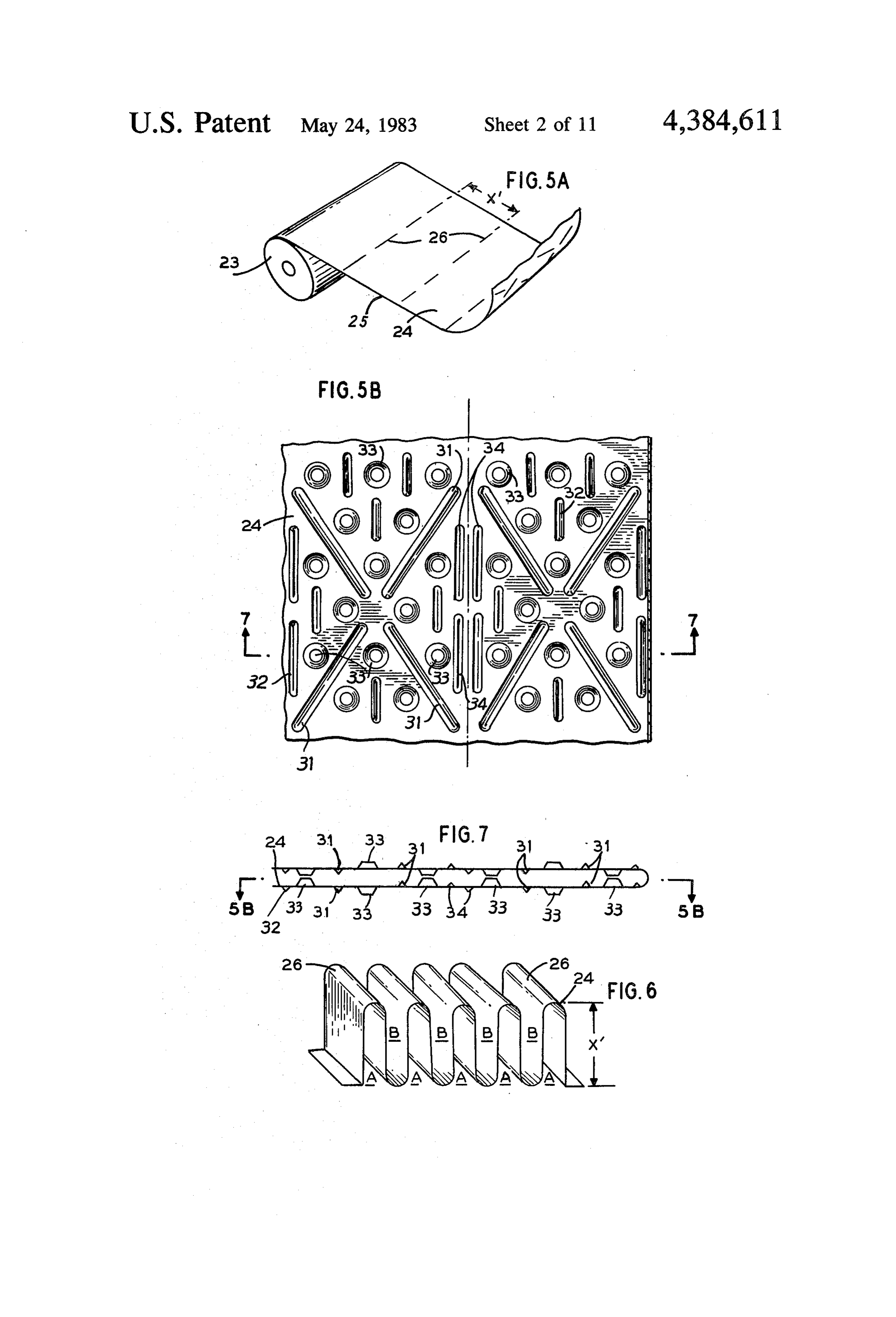
however the exposure that is provided is sufficient for a FIG. 5A is a perspective view of a foil strip; thorough cleaning and for certain repairs if necessary. 50 FIG. 5B is a plan view of a portion of one panel of the It is also possible for the front and/or rear cover foil after being die-formed;
plates to be provided by a surface of another similar FIG. 6 is a strip of foil from FIG. 5A, folded into apparatus to which the new heat exchanger is attached. successive U-bends for defining fluid passageways in The result with a common wall would be equally strong the core portion of the heat exchanger; and efficient, while rendering the basic apparatus sub 55 FIG. 7 is a fragmentary end view of the folded sheet stantially simpler and cheaper to construct. material of FIG. 6, showing spacer elements between A further benefit of the structure of the new inven adjacent partition walls;
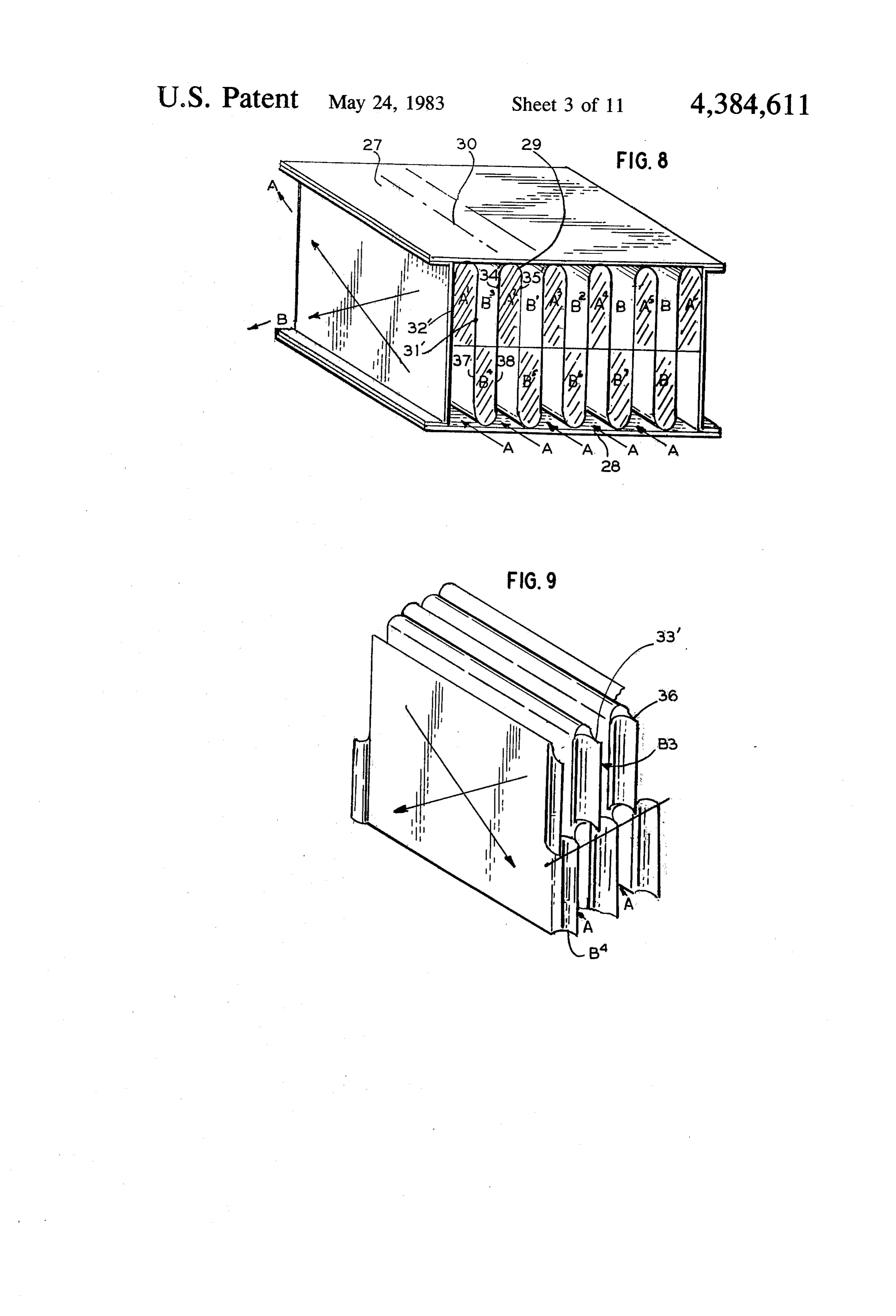
tion is that fluid entering the device, flowing through FIG. 8 in a schematic representation, shows a stage of and discharging from the device will have a very small assembly of a Series-X heat exchanger with top and pressure drop, because all the in-flow apertures at one bottom walls placed to close the open sides of the pas end are aligned and spaced apart, and a manifold can Sages;
direct fluid linearly through the manifold and into the FIG. 9 is a fragmentary perspective view of a core inlet apertures, and thence through the device with corresponding to FIG. 6, showing the construction minimal turning of the fluid or associated friction losses. stage whereby certain end edges of the passageways are Although various metals or combinations of metals 65 pinched together and thereby closed;
can be used, corrosion will be minimized or prevented FIG. 10 is a partial perspective view corresponding where constructions are totally aluminum or totally to FIGS. 6 and 9, showing further detail of the struc stainless steel. As described earlier there will no cross ture, wherein alternate upper and lower end edges are
Page 15
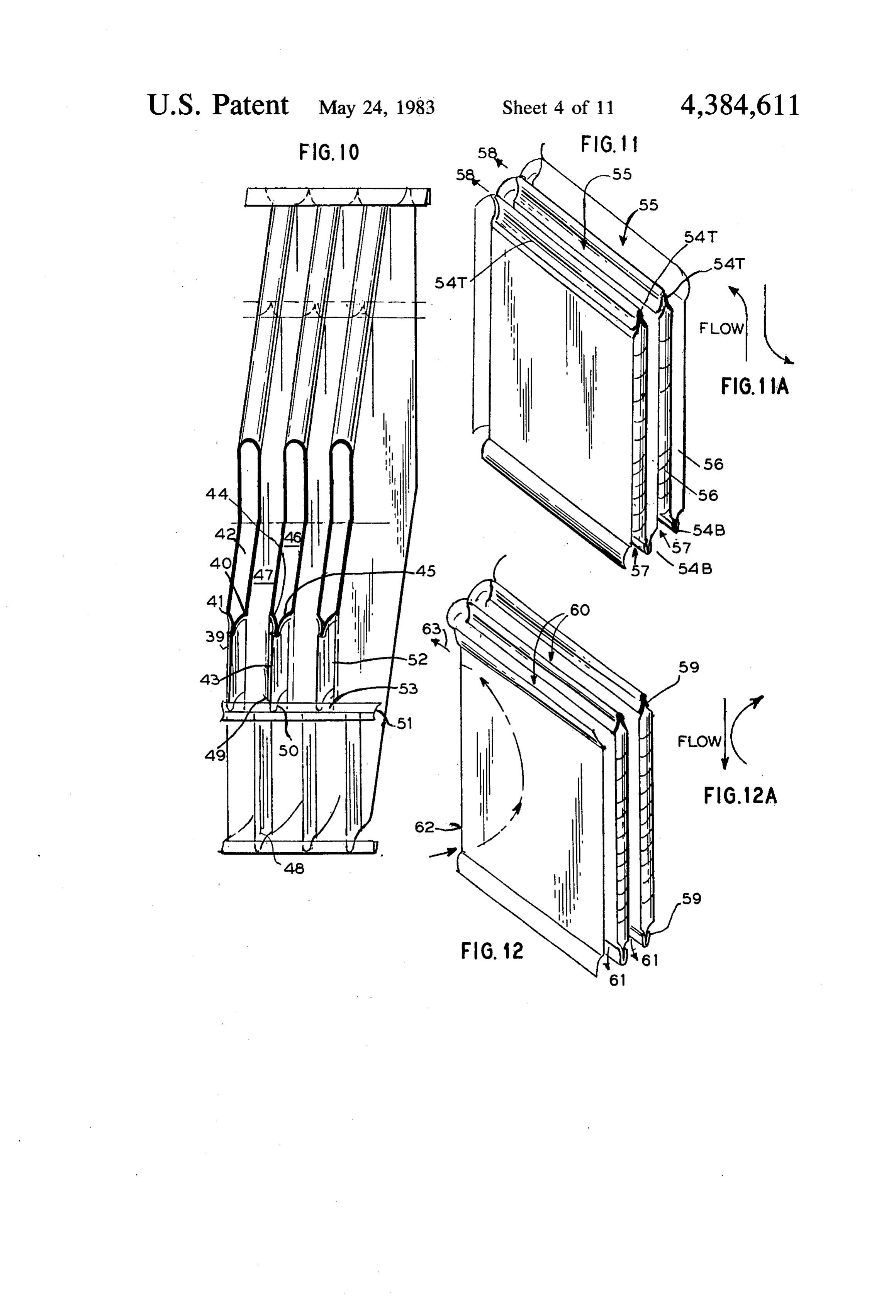
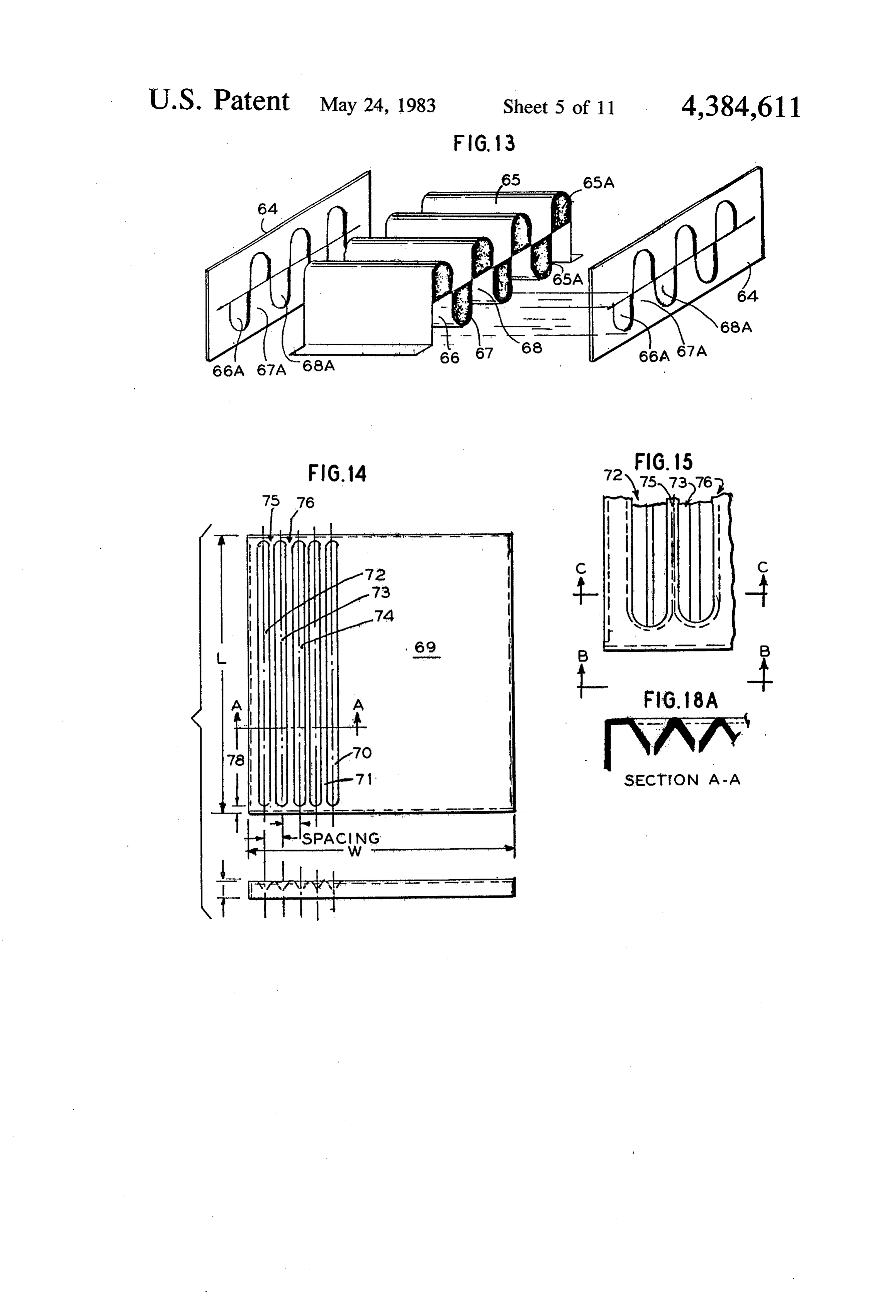
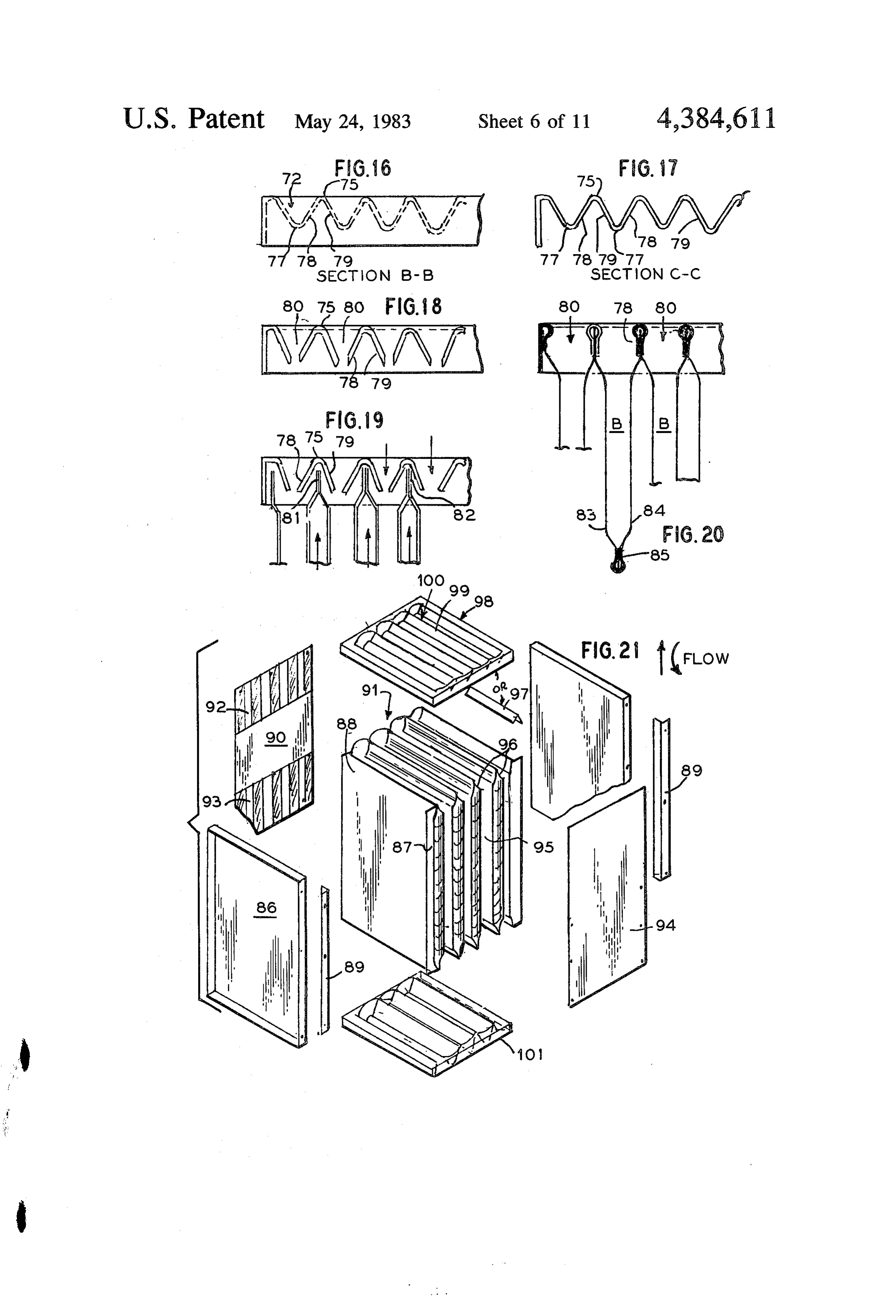
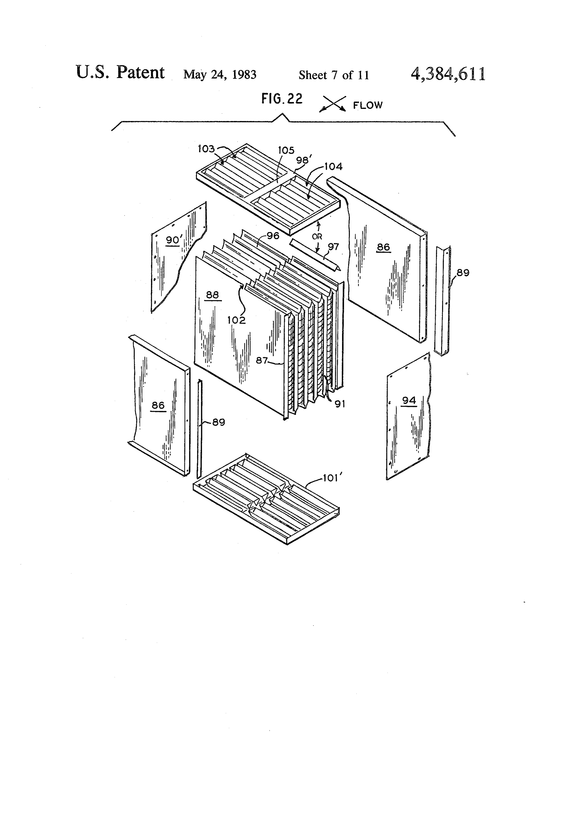
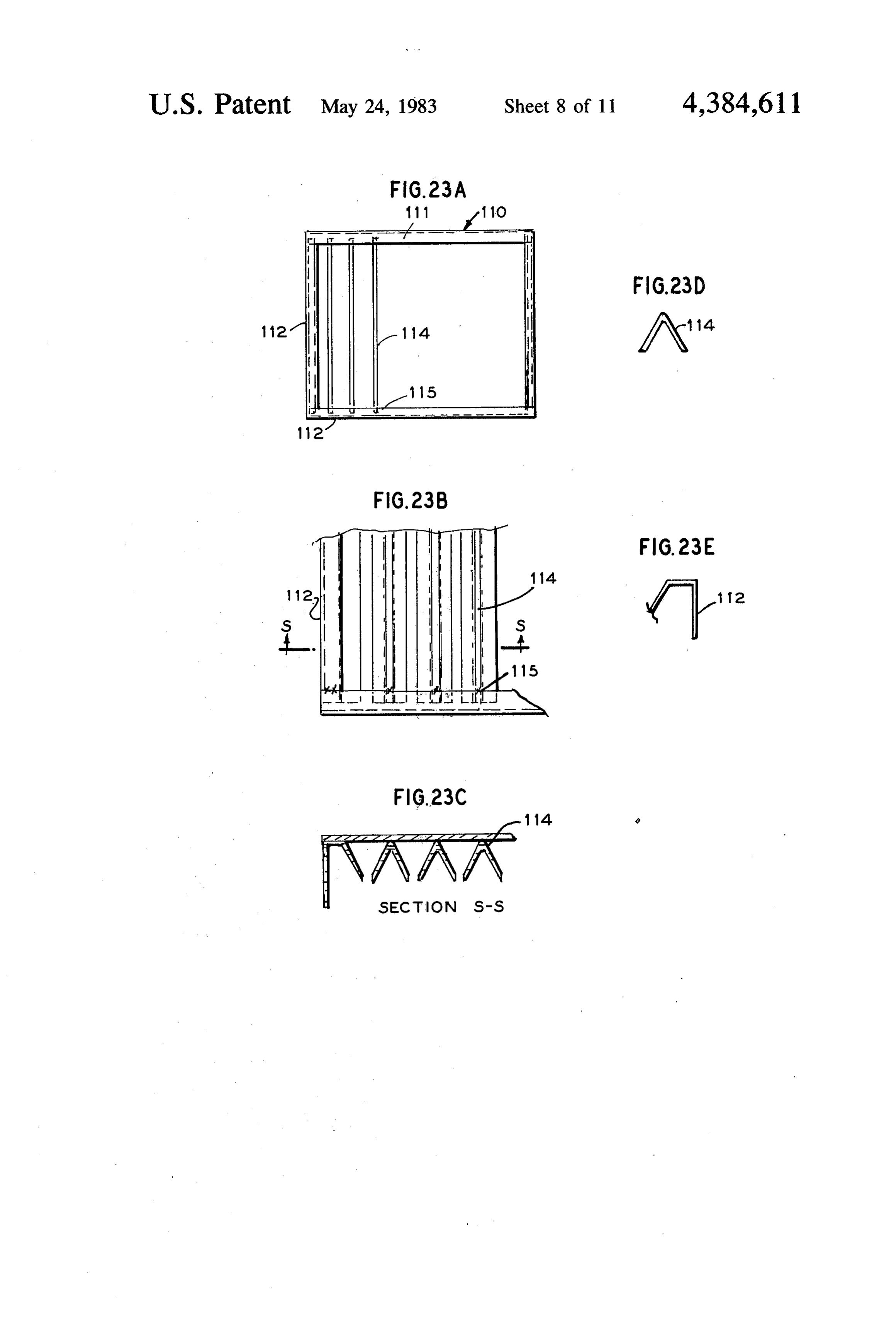
pinched to seal off selected passageways in the core FIGS. 1-3 will be described in detail below as regards portion of the heat exchanger; their structural features, operation, and resulting advan FIG. 11 is a fragmentary perspective view corre tages. FIGS. 1A, 2A, and 3A are provided to help clar sponding generally to FIG.9, but illustrating a Series-H ify the internal fluid flow paths in FIGS. 1, 2, and 3 heat exchanger of FIG. 2; respectively, and the reference numerals for the same FIG. 11A shows schematically the flow path through components in corresponding figures are the same; ref the heat exchanger of FIG. 11; erence to FIG. 1 for example, is intended to include FIG. 12 is a fragmentary perspective view corre FIG. 1A. In each of these embodiments there is a cen sponding generally to FIG. 9, but illustrating the Series tral core portion of the heat exchanger which is formed K heat exchanger of FIG. 3; O by a single continuous strip of metal or foil folded in FIG. 12A shows schematically the flow path through accordian style to provide a plurality of relatively nar the heat exchanger of FIG. 12; row and adjacent passageways for the various heat FIG. 13 in a schematic representation, is an exploded transfer mediums. These heat exchangers are essentially perspective view showing another assembly stage of the rectangular, having side walls S essentially parallel to heat exchanger core, with the front and rear end walls 15 the internal partition walls W which define the flow positioned to cooperate with the folded foil for defining passages, top or front walls F, opposite bottom or rear the sealed ends of various passages; walls, and opposite ends through which the fluid pas FIG. 14 is a plan view of one end cap (front or rear sageways discharge or receive the gaseous or other wall) for the core of the heat exchanger; fluid medium. The shaded areas between adjacent parti FIG. 15 is a fragmentary detail view of the end cap of 20 tions W indicate the portions of the ends or front sides FIG. 14; of the passages that are closed, while the clear spaces FIG. 16 is a fragmentary elevation view, taken along between partitions indicate inlet and discharge aper line B-B of FIG. 15; tures of these passages.
FIG. 17 is a fragmentary elevation in section taken There are three principal embodiments illustrated, along line C-C of FIG. 15; 25 namely Series X, H and K heat exchangers. In all these FIG. 18 and FIG. 18A is a fragmentary elevation embodiments the basic fluid flow pattern is counter similar to FIG. 17, illustrating the next step of construc flow with arrows H, C in FIGS. 1-3 indicating the tion, wherein the lower portions of the grooves are general directions of hot and cold flows respectively. pierced; FIG. 1 represents the Series X heat exchanger, wherein FIG. 19 is a fragmentary view illustrating an initial 30 the flow follows an X-shaped pattern; hot fluid enters step of assembly of the end cap of FIG. 18 with pinched the upper right end E1 and exits from the lower left end ends of the heat exchanger core, wherein each pinched E2, while cold fluid enters the upper left end E3 and end is inserted within a U-shaped groove portion; exits the lower right end E4. FIG. 2 represents the Se FIG. 20 is similar to FIG. 19 illustrating the next step ries H heat exchanger wherein the hot flow enters one of assembly, wherein the U-shaped walls are crimped 35 end E5, traverses the length of the passage, and exits an about the pinched portions of the core, thereby sealing end portion of the front surface E6F while cold flow same and simultaneously providing passageways be enters the opposite end E6, traverses the length of the tween the core walls; flow passages, and exits an end portion of the rear sur FIG. 21 is an exploded perspective view showing an face E5R.
assembly of the new Series-K heat exchanger, with FIG.3 represents the Series Kembodiment, wherein frames for strengthening the side walls thereof; the hot flow for example enters one end E7, traverses FIG. 22 is similar to FIG. 21 for a Series X heat the length of the passages and exits the opposite end E8, exchanger; while the cold flow enters an end portion of the front FIG. 23A is a plan view of an end cap, with the surface EgF near the discharge end E8 of the hot fluid, grooves formed by welding; 45 flows through the passage and exits through an end FIG. 23B is a detail of one corner of FIG. 23A; portion of the front surface E7F adjacent the end E7 of FIG. 23C is a sectional view taken along line S-S of the device where the hot fluid enters. FIG. 23B; FIG. 4 is an intentionally distorted view of the heat FIG. 23D is a detail sectional view of a rib in FIG. exchanger like that of FIG. 1, and presented in this 23B and 23C. 50 manner to illustrate more clearly the flow pattern in the FIG. 23E is a detail sectional view of the frame of Series X embodiment. Accordingly, heat exchanger 10 FIGS. 23B and 23C. has a side wall 11 and a right end 16 and a left end 17, FIG. 24 is an exploded perspective view of a Series-K and a top (or front) surface 18 and a bottom (or rear) heat exchanger, that is a variation of FIG. 21; and surface.
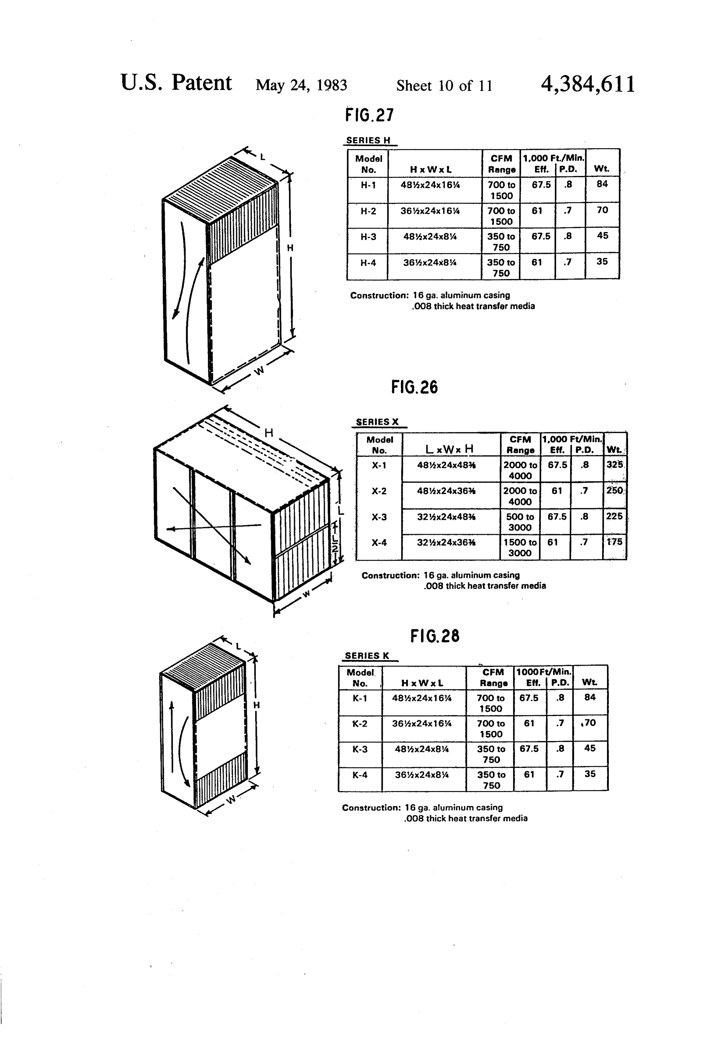
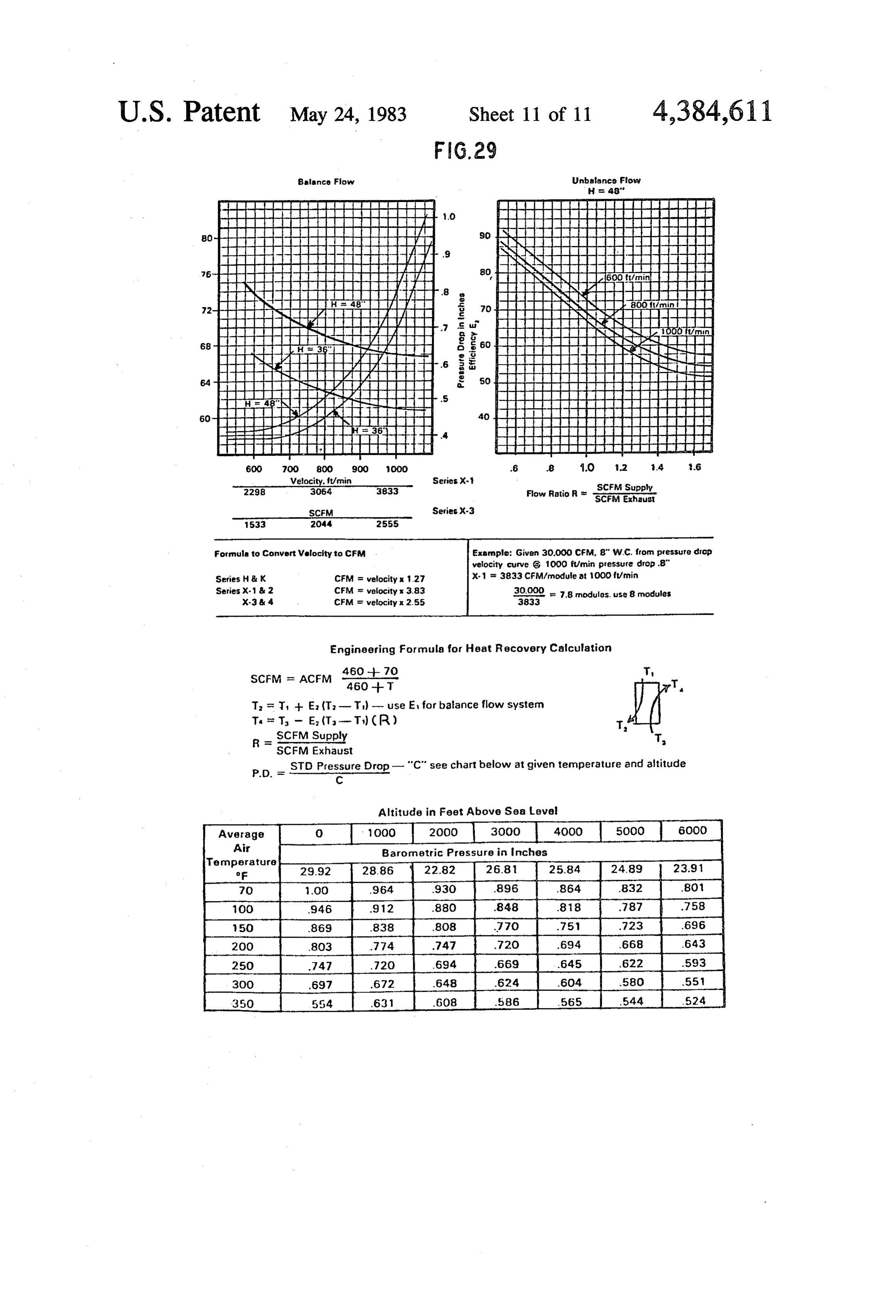
FIG.25 is an exploded perspective view of a Series-X 55 Now consider the first wall portion 19 visible at both heat exchanger, that is a variation of FIG. 22. ends 16 and 17; this wall portion 19 and outer wall 11 FIGS. 26, 27, and 28 are charts showing dimensional define the first passageway through which fluid flows and operational data respectively for Series-X, Series from left to right as indicated by arrow 20. More partic H, and Series-K heat exchangers of various sizes made ularly the fluid enters via the upper portion at the left according to this invention. end 17, and travels generally diagonally downward to FIG. 29 is a sheet of additional operational data for the lower portion of the right end 16. Now consider the Series-X, H, and K heat exchangers according to the second wall partition 21 illustrated at both ends of the present invention. : heat exchanger. Walls 21 and 19 define the second flow
DETAILED DESCRIPTION OF THE
passage adjacent to the first, and as evidenced by arrow 65 22, the cold fluid enters at the upper right portion of this
PREFERRED EMBODIMENTS passage at the right end 16 and travels diagonally down The new invention is a heat exchanger which may ward to the lower left of this passage exiting as shown take a variety of forms. Three preferred emodiments in at end 17. Consequently the flow patterns through the
Page 16
adjacent passages as indicated by arrows Hand C define square feet. In contrast, with 92 panels 36 inches long an X-shaped pattern. . . ... . and 8 inches wide, the strip would be 63 feet long, pro FIG. 4 further illustrates how the end surfaces of the viding an area of 188 sq. feet. As discussed earlier in upper and lower portions are alternately blocked to FIG. 4 for example, alternate passageways as indicated define the passages as described. Thus all the hot fluid by A in FIG. 6 would contain the relatively hot fluid, enters the upper left side through alternte inlet aper while the interspersed passages indicated by B in FIG. tures and discharges at the lower right end through the 6 would contain the cold fluid. Subsequent figures illus alternate exit apertures; and all the cold fluid enters via trate how passageways A and B are sealed at the top the upper right end and discharges via the lower left and bottom and blocked in part at opposite ends. end. In this manner it is relatively easy, for example, at 10 FIG. 8 shows the next step of construction of the heat left end 17, to separate the hot flow into the upper aper exchanger after the sheet 24 is formed into the accord tures from the cold flow in the lower apertures, and to ian folds of FIG. 6, with fluid passages A, A1A2, B, B1, conveniently manifold these flows in connection with B2 etc. identified. Top and bottom plates 27 and 28 are inlet and outlet ducts. positioned to close the exposed sides of alternate pas Another advantage of this arrangement is that the 15 sages formed by the folded sheet. It might be noted that overall pressure drop of the fluid through the device is the top portion 29 of one particular fold engages a cor maintained at a minimum, because the fluid is not re responding portion 30 indicated in dotted line along the quired to turn around curves in order to be divided into top wall 27. Should there be leakage between passages separate inlet and outlet flows for the various passage B1 and B2 in FIG. 8 because of an incomplete seal along ways. More particularly, the fluid could flow continu 20 area 30, it would not matter because the fluid in B1 and ously in one direction from a single source, then be B2 is essentially the same. While the fluid flows are divided into separate chambers in the same direction generally maintained in their respective passageways, which communicate directly with the alternate open the fact that slight leakage in this area makes no differ ings at one end of the apparatus; the fluid could con ence, is particularly beneficial to the new design be tinue generally in a straight line through the device and 25 cause no sealant is needed in this area. To the extent that exit at the opposite end and be recombined into a single sealant is eliminated, similarly the corresponding labor outlet in a similar manner. effort and cost is reduced. Construction of the new heat exchangers typically FIG. 8 also shows the blocking of portions of various begins as illustrated in FIG.5A with a roll 23 of deform passages in order to establish the Series X cross-flow or able foil 24 in the form of a long strip that may have 30 counter-flow flow pattern. More specifically by com widths of 24', 36" or 48". The exposed end 25 of the foil paring FIGS. 6 and 8, the upper parts A in FIG.8 of the is die-formed to define in its surface fold lines 26 and a passages A from FIG. 6 are blocked, while the lower pattern 27 of projections and depressions in the form of parts B in FIG. 8 of all the passageways B in FIG. 6 are ribs and buttons. The foil may be aluminum, stainless blocked. As is seen in earlier FIG.4, at the opposite end steel or other suitable heat exchange material; the exam 35 of each passage A for example, the lower portion of the ple shown is aluminum having thickness in the range of passagve is blocked, whereas the upper portion is open; 0.003' to 0.080', and in this case 0.008'. this alternate blocking is typical throughout the device The general approach to construction is to form con as was explained earlier. The manner of creating the secutive U-bends in the strip as shown in FIG. 6, along blockages will be shown in subsequent figures. the bend lines shown in FIG. 5A. The bends in this FIG. 9 shows the next step in construction; the continuous strip form a first set of alternate passages. A pinched portion A1 of FIG. 9 corresponds to the open on the downward side, and a second set of alter blocked portion A1 in FIG. 8. What has been done is nate passages B open on the upward side; the dimension that edges 31' and 32 of blocked area A1 in FIG. 8 have X" of each panel or partition wall in FIG. 6 corresponds been pinched together into the closed end 33 in FIG. 9. to the dimension X" in FIG. 5A between adjacent fold 45 Similarly the edges 34 and 35+ of blocked portion A2 lines. in FIG.8 have been pinched together to form the closed The pattern 27 of ribs and buttons formed on the foil end 36 in FIG. 9. After such pinching there remains the strip in FIG. 5A, is shown in detail in FIG. 5B. There clear passageway indicated as B3 in FIGS. 8 and 9. are diagonal ribs 31, axial ribs 32 and 34 and buttons 33. Similarly as shown in FIG. 8 there are pinched portions The various ribs are to stiffen the foil walls to resist at the bottom namely at B4 and B5 for example which bending and warping in all directions; the buttons are to are formed by pinching the edges 37 and 38 of the ends function as spacers to prevent adjacent walls from con of the folded sheet metal. It should be apparent with this verging and constricting the fluid flow therebetween. kind of alternate pinching and exposed openings, that FIG. 7 illustrates how the button pattern of one panel is the X-shaped flow pattern will result for the Series X the mirror image of the adjacent panel, so that buttons 55 heat exchangers.
33 become aligned, contact each other, and serve to FIG. 10 shows further details of the embodiment of space the walls apart and add structural rigidity to the FIG. 9. At the lower left portion of FIG. 10 there is assembly. shown a pinched portion 39 formed by closing edges 40 When a sheet or foil is folded as indicated in FIGS. 6 and 41 of the first passage 42; there is an adjacent and 7, for example, the spacing between any two parti 60 pinched part 43 formed by closing the edges 44 and 45 tions is approximately of an inch, and accordingly a of the second passage 46, while thereby leaving be typical button would extend approximately of an inch, tween them the open passage 47. At the bottom, the so that a pair of mating buttons would meet in the mid alternate passages are established by the closure 48, for dle of a space between two partitions and equal the total example, using edges 49 and 50 of the second and third space of one quarter inch. In one example of a strip 65 wall portions. In FIGS. 9, 10, 22 and 25, the edges of the having 92 folds, and each panel having a length of 48 partitions are notched or slit to better facilitate the divi inches and a width of 32 inches, the strip would have to.. sion of passageways, and a T-shaped divider clip 51 be 245 feet long and would provide an area of 981 (FIG. 10) is installed at the dividing line between the
Page 17
upper passages and lower passages. Preferably, this In the next stage of assembly after the appropriate T-clip is secured at the time the V-clips 52 are crimped end edges of the folded sheet metal have been pinched about the joined edges of the partitions; if necessary a together as indicated at 81 and 82 for example in FIG. small amount of sealant is added at areas 53, i.e., the 19, the end plate 69 is moved into position such that a junctures of the pinched portions and the T-shaped clip. pair of downward extending legs 78 and 79 of a rib 75 In small units where less strength and rigidity are re overlie the pinched portion 81, and similar concave ribs quired the notches and T-clip are replaced by a flat strip overlie corresponding pinched portions as indicated. and sealant as shown in FIG. 25. FIG. 20 illustrates how the legs 78 and 79 are com FIG. 11 shows a view similar to that in FIGS. 9 and pressed or pinched about the pinched portion 81 form 10; however, the edges 54T at the top and 54B at the 10 ing a permanently joined and sealed unit. With this bottom are pinched closed along their entire length. construction, the result is a wide opening 80 between Thus, each passageway is open at one end and one side, each two pinched edges which readily admit the flow of and closed at the opposite end and side. Consequently, fluid into adjacent chambers marked B in FIG. 20. At all the hot fluid can enter alternate passages at the top the opposite end the alternate walls indicated as 83 and end 55 flow the length of the heat exchanger, and then 15 84 are pinched together with a corresponding concave exit through a discharge area 56 on the front surface. rib section 85 as symbolically indicated in FIG. 20. Meanwhile, the cold fluid has entered alternate cham Since a typical end plate 69 is essentially a single sheet bers through the bottom end 57, flows the length of the which is die-punched and then cut to provide the ex heat exchanger, and exits through the opposite rear side 20 posed edges of the concave ribs, the entire flow pattern 58, producing the flow path for the Series H heat ex can be established by placing such an end plate into changers indicated in the symbolic representation of proximity of the end edges of the folded core portion. F.G. 11A. Then by appropriate pinching of selected portions of FIG. 12 illustrates the Series K heat exchanger, the end edges of the accordian folded core and assembly which is made somewhat similarly to the Series H heat 25 thereto of the end plate, the flow paths are established. As indicated earlier in a separate assembly step repre exchanger, in that the end edges 59 are pinched along their full length so that fluid of one temperature enters sented to close by FIG. 8, the top and bottom walls are secured the open fourth side of each passageway; FIG.
one end 60, travels the full length of the heat exchanger and out the other end 61; simultaneously, fluid of a 21 illustrates further assembly of a preferred embodi ment. More particularly for strength and further attach different temperature extreme enters the front at one 30 ment end 62, travels the length of the heat exchanger, and walls to other components of a broader system, the side discharges through the front at the other end 63 in the within thestrengthened are by a frame portion 86 which fits flanged end 87 of the outer partition wall 88.
K flow pattern. At the junction of flange 87 and frame 86 an angle plate Next we will consider the manufacture and assembly 89 is added for helping to seal the space and further of the end plates 64 with the folded foil 65, as schemati 35 strengthen the assembly.
cally represented in FIG. 13. The shaded areas 65A at the ends of certain passages represent areas closed as by ture may be usedearlier
As indicated for a the basic heat exchanger struc variety of different counter-flow pinching the adjacent walls together, as described ear configurations by simply varying the latter stages of lier. Between these closed part are open passages, and construction, and thereby altering the fluid flow paths the end plates will have corresponding open and closed to produce the Series X, H, K or other designs. Accord parts. Thus, passage 66 aligns with aperture 66A of the ingly, the heat exchanger core of FIG. 21 may be end plate; pinch 67 aligns with wall 67A of the end plate formed into a K-series system, for example, by the fol and will be joined thereto; passage 68 aligns with aper lowing construction. A rear plate 90 is added to cover ture 68A; etc. A preferred actual end plate is described and seal the middle area of the passages 91 whose open below. 45 sides face rearward; at the top and bottom respectively, FIGS. 14-18 illustrate how the end plate is made, and of plate 90 are inlets 92 and outlets 93 for communicat FIGS. 19 and 20 illustrate how this completed end plate ing with passages 91; a front plate 94 is added to cover is assembled with a folded sheet metal to produce the and seal the full length of the passages 95 whose open final joint. FIG. 14 illustrates the plan view of a typical sides face forward. The top end edges 96 of passages 91 end plate 69 showing a plurality of closely spaced elon 50 are closed and sealed by either individual seal strips 97 gated depressions 72,73, 74, etc. FIG. 15 shows a frag or by end plate 98 with its integral seal strips 99. Be mentary detailed view of the sheet 69 of FIG. 14. As tween the seal strips are spaces or apertures 100 for indicated there are downward depressions or grooces communication with passages 95. Bottom plate 101 is 72,73 and 74 with strips 75 and 76 for example, between similar to top plate 98.
the grooves. The front elevation view of FIG. 16 taken 55 FIG.22 illustrates the assembly of a Series X counter along line B-B of FIG. 15, illustrates that for groove flow heat exchanger, which is generally similar to as 72 for example, there is a bottom part 77, and the adja sembly in FIG. 21 of a Series K heat exchanger. The cent strip 75 has downward extending legs 78 and 79. basic core part is a single strip of metal folded to define FIG. 17 shows a sectional view taken along line C-C the parallel passages; however, in this version the end of FIG. 15, thereby illustrating more clearly the groove edges of the partition walls have slits or notches 102 to portions 77 and strip portions 75 with downward ex aid in separating the hot ducts 103 from the cold ducts tending leg portions 78 and 79. 104. Again there is the choice of individual seal strips 97 As shown in FIG. 18 the end plate 69 has been die or an end plates 98', except that this end plate has a punched and the bottom portions 77 of each depression divider strip 105 which becomes positioned in the or groove have been pierced, severed or otherwise 65 notches 102 and is sealed therewith; bottom end plate removed. What remains are a plurality of concave ribs 101' is similar. To complete assembly of this Series X such as 75 with downward extending legs 78 and 79 and apparatus front plate 94, rear plate 90', and side plates or passageways 80 between each two ribs. frame 86 are added and secured.
Page 18
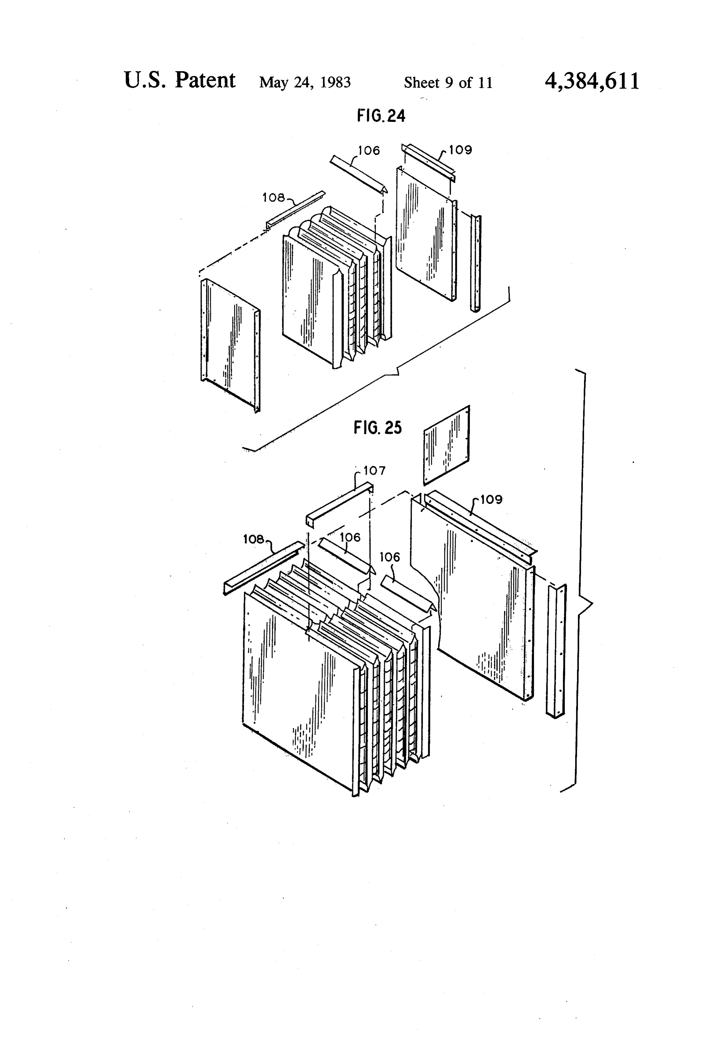
FIGS. 24 and 25 illustrate assembly techniques simi 1. In a heat exchanger including a housing and a core lar to FIGS. 21 and 22, but using individual seal strips part having a plurality of generally parallel partitions 106 instead of end plates, adding divider strips 107, and defining between them fluid fow passages which are finally adding strips 108 and 109 to form a supporting alternately spaced as even-numbered and odd-num frame about the partitions. These frames should be ade bered passages respectively for relatively hot and cold quate for smaller apparatus or those subject to lesser fluids to flow in counter-flow heat exchanger relation stress loads. When using the divider strips 107, either ship, the improvement wherein said core part com float or T-shape, which traverse and engage the prises:
notched areas of the partitions, it is possible to use very (a) a continuous metal strip folded in successive re little sealant, since the foil partitions are quite maleable O verse bends thereby defining said partitions and and can be easily bent and crimped to seal the fluid intermediate strips between and connecting said passage. partitions, whereby each two adjacent partitions FIG. 23A illustrates a different version of the end and intermediate strip define walls of one of said plate 110 which is formed by weld construction instead 15 passages with a remaining open side and opposite of a single piece of sheet metal die-punched into shape. edge ends,
Accordingly, a rectangular frame 111 is formed of four (b) first side closure means for closing a portion of beams 112 and 113 welded or brazed together as in FIG. said open sides on said one side of said core, 23B. Next the V-shaped ribs 114 are positioned and (c) second side closure means for closing a portion of welded or brazed at their ends 115 as indicated, to pro 20 (d)the open sides on said other side of said core, first edge end closure means for closing adjacent vide a die-punched sheet structure of FIG. 14, without edge ends of partitions on one end of said core for having to carry out the steps: creating an appropriate establishing between said closed adjacent edge die, die-punching the flat sheet in its origional form, and ends openings to said passages, then severing the bottoms of the depressions to provide the concave or V-shaped ribs. FIGS. 23C, D and E 25 (e)cent second edge end closure means for closing adja edge ends of partitions on the opposite end of illustrate further details of this frame 110. This welded type end plate has the advantage of reduced cost for said core for establishing between said closed adja initial construction because simple standard form pieces cent edge ends openings to said passages, can be used, however, for high volume the welding (f) whereby said first and second side closure means piece would be more expensive, because of the multiple 30 together with said first and second edge end clo pieces and considerable labor expense in assembling all sure means establish said passages into a counter these different parts together. flow system of said even-numbered and odd-num It should be understood that a significant accomplish bered passages, and (g) partition spacing means for spacing adjacent parti ment of the present invention is the provision of heat tions which define the walls of a passage to permit exchangers that are at least as thermally efficient as 35 angular fluid flow comprising a plurality of sepa others, but are significantly simpler, lighter in weight, rated projections which project from a partition and less expensive than comparable prior art units. Less surface toward the adjacent partition which forms sealant is required, and where the die-punched single the passage, said projections being arranged in a piece end plate is used, the welding of a plurality of pattern providing for angular fluid flow between parts is avoided. In fact, with the crimping technique, 40 projections so that fluid flows angularly throughut all welding steps may be avoided. Also, these new de the entire passage.
vices are quite small and compact, and are readily 2. Apparatus according to claim 1, wherein each end adaptable for use in more comprehensive systems. A of said passages is defined by edges of said adjacent still further advantage in regard to both economics and partitions extending in the same direction, and each of convenience, is the ease of cleaning, inspecting and 45 said first and second edge end closure means comprises repairing these new heat exchangers by merely remov a sealing junction of said edges for the part of each end ing the panels which cover the open sides of the fluid that is closed.
passages. With such removal one can easily see and 3. Apparatus according to claim 2, wherein each of have access well into the passageways. By utilizing a said sealing junctions has opposite sides generally paral single strip with successive reverse bands to form the 50 lel to said partition, and each of said first and second passages, cross-contamination is essentially eliminated, edge end closure means for a typical junction comprises since the majority of prior art junctions of separate a seal strip of deformable material overlying and folded partitions are no longer employed. The features de and crimped about both sides of said junction. scribed above and others simplify and reduce the cost of 4. Apparatus according to claim 3, wherein said seal manufacture dramatically, to an extent hardly expected 55 strip is generally V-shaped in cross-section before being in this otherwise extensively developed field. Thus, the crimped onto one of said junctions. new structural features and/or manufacturing tech 5. Apparatus according to claim 3, wherein each of niques disclosed and claimed herein, have provided said first and second edge end closure means is an end significant and valuable progress in the heat exchanger plate comprising a frame and a plurality of said seal art. 60 strips traversing said frame and spaced apart distances The embodiments illustrated and described above for corresponding to the spacing of said passages whose heat exchangers, methods of making same, and the foil ends are to be closed.
for these devices are merely representative of broader 6. Apparatus according to claim 5, wherein said seal concepts which are the subjects of this application and strips are separate components having ends which are are presented in the claims. Accordingly, various modi 65 secured to said frame.
fications of these disclosures are possible within the 7. Apparatus according to claim 5, wherein said end spirit and intent of this invention and appended claims. plate comprises a single piece of sheet metal die What is claimed is: punched and cut to define a plurality of said strips with.

Page 19
a slot defined between each two adjacent strips as an pattern of depressions extending donward and projec aperture for fluid flow into or out of one of said pas tions extending upward in the surface theroef, said de Sages. pressions and projections comprising spacers of said 8. Apparatus according to claim 1, described with partition spacing means for adjacent passages, and to said passages oriented to extend generally from left to still further define in each partition stiffening ribs, said right, the improvement wherein each end of a passage stiffening ribs comprising first elongated stiffening ribs has upper and lower portions, said first edge end closure extending generally parallel to and adjacent said bend means closes the right end upper portions and said sec lines and second elongated stiffening ribs extending ond edge end closure means closes the left end lower diagonally relative to said bend lines, said second elon portions of the even-numbered passages, and said first 10 gated stiffening ribs defining Xs with said first elon edge end closure means also closes the right end lower gated stiffening ribs and said spacers being situated portions and said second edge end closure means also between the arms of the Xs, said patterns of ribs and closes the left end upper portions of the odd-numbered spacers in one partition being essentially the same as the passages, thereby providing an "X-Series' counter-flow pattern in the adjacent partition, except that where ribs system, whereby hot fluid may flow from the upper left 15 extend upward in one partition the corresponding ribs to the lower right of the even passages and cold fluid in the adjacent partition extend downward, and where a may flow from upper right to lower left of the odd spacer extends upward in one partition the correspond passages. ing spacer in the adjacent partition extends upward also, 9. Apparatus according to claim 1, described with and similarly corresponding spacers extend downward said passages oriented to extend generally from top to 20 in adjacent partitions, whereby for typical adjacent bottom, and said open sides of the passages facing for partitions folded with their up sides facing each other, ward and rearward and having upper and lower por tions adjacent said top and bottom ends respectively, corresponding toward each upward extending spacers will extend other for keeping the partitions apart, and the improvement wherein, for said even-numbered pas corresponding stiffening ribs will have essentially the sages, said third closure means closes the top ends same spacing between them
as the space between the thereof and said first closure means closes the lower partitions so as not to restrict fluid flow between said portions of the front sides of these passages, and for said partitions.
odd-numbered passages, said fourth closure means 12. In a heat exchanger according to claim 1, the closes the bottom ends thereof and said second closure improvement means closes the upper portions of the rear sides of of said "X-, H- 30 wherein said core part is formed into one these passages, thereby providing an "H-Series' coun change system configurations and K-Series' counter-flow heat ex ter-flow system, whereby hot fluid may flow into the according to the parts of bottom of the even-numbered passages and out of the closed. said open sides and edge ends of the passages which are front upper portions thereof, and cold fluid may flow into the top of the odd-numbered passages and out of 35 13. A heat exchanger according to claim 1 wherein the rear lower portions thereof. said continuous metal strip comprises sheet metal which 10. Apparatus according to claim 1, described with is bendable to form the partitions which define between said passages oriented to extend generally from top to them fluid flow passages, said strip being die-punched bottom, and said open sides of the even-numbered pas to define in the surface thereof adjacent partitions sepa sages facing rearward and of the odd-numbered pas 40 rated by bend lines extending transversely of the length sages facing forward, with upper and lower portions of of the strip, and to further define in each partition a said open front side adjacent said top and bottom ends pattern of depressions extending downward and projec respectively, the improvement wherein, for said even tions extending upward in the surface thereof, said de numbered passages, openings are maintained in the top pressions and projections comprising spacers of said and bottom ends thereof and said first closure means 45 partition spacing means for adjacent passages, and to closes the rear open sides, and for said odd-numbered still further define in each partition stiffening ribs, said passages, said third and fourth closure means close both patten of ribs and spacers in one partition being essen ends thereof and said second closure means closes the tially the same as the pattern in the adjacent partition, front sides intermediate said upper and lower portions except that where ribs extend upward in one partition thereof, thereby providing a "K-Series' counter-flow 50 the corresponding ribs in the adjacent partition extend system, whereby hot fluid may flow into the bottom and downward, and where a spacer extends upward in one out the top of the even-numbered passages, and cold partition the corresponding spacer in the adjacent parti fluid may flow into the upper portion of the front side tion extends upward also, and similarly corresponding and out of the lower portion of the front side of the spacers extend downward in adjacent partitions, odd-numbered passages. 55 whereby for typical adjacent partitions folded with 11. A heat exchanger according to claim 1 wherein their up sides facing each other, corresponding upward said continuous metal strip comprises sheet metal which extending spacers will extend toward each other for is bendable to form the partitions which define between keeping the partitions apart, and corresponding ribs will them fluid flow passages, said strip being die-punched have essentially the same spacing between them as the to define in the surface thereof adjacent partitions sepa 60 space between the partitions so as not to restrict fluid rated by bend lines extending transversly of the length flow between said partitions.
of the strip, and to further define in each partition a
Provenance
- Collection
- Cited prior art
- Original PDF
- patentimages.storage.googleapis.com →
- Filed
- 1980-10-28
- Pages
- 19
- Method
- pdftotext (the PDF's own text layer) + pdftoppm 300dpi page scans
- Source
- Google Patents bibliographic record
- Granted
- 1983-05-24
- Inventors
- James Y. Fung; HXK Inc
- Transcribed from
- patentimages.storage.googleapis.com →