patent · US4588659
Fuel vaporizer
13 May 1986
Page 1 — bibliographic record
United States Patent (19) 11 Patent Number: 4,588,659 Abens et al. 45) Date of Patent: May 13, 1986 54 FUEL VAPORIZER (56) References Cited
75 Inventors: Sandors G. Abens, Rye, N.Y.; 3,522,019 7/1970 Buswell et al. ..................... 420/190 William Keil, Redding, Conn. 3,635,682 1/1972 Vine et al. ....... . 23/288 R 4,455,152 6/1984 Hansen .................................... 48/61 (73) Assignee: Energy Research Corporation, Primary Examiner-Jay H. Woo
Danbury, Conn. Assistant Examiner-Jennifer E. Cabaniss
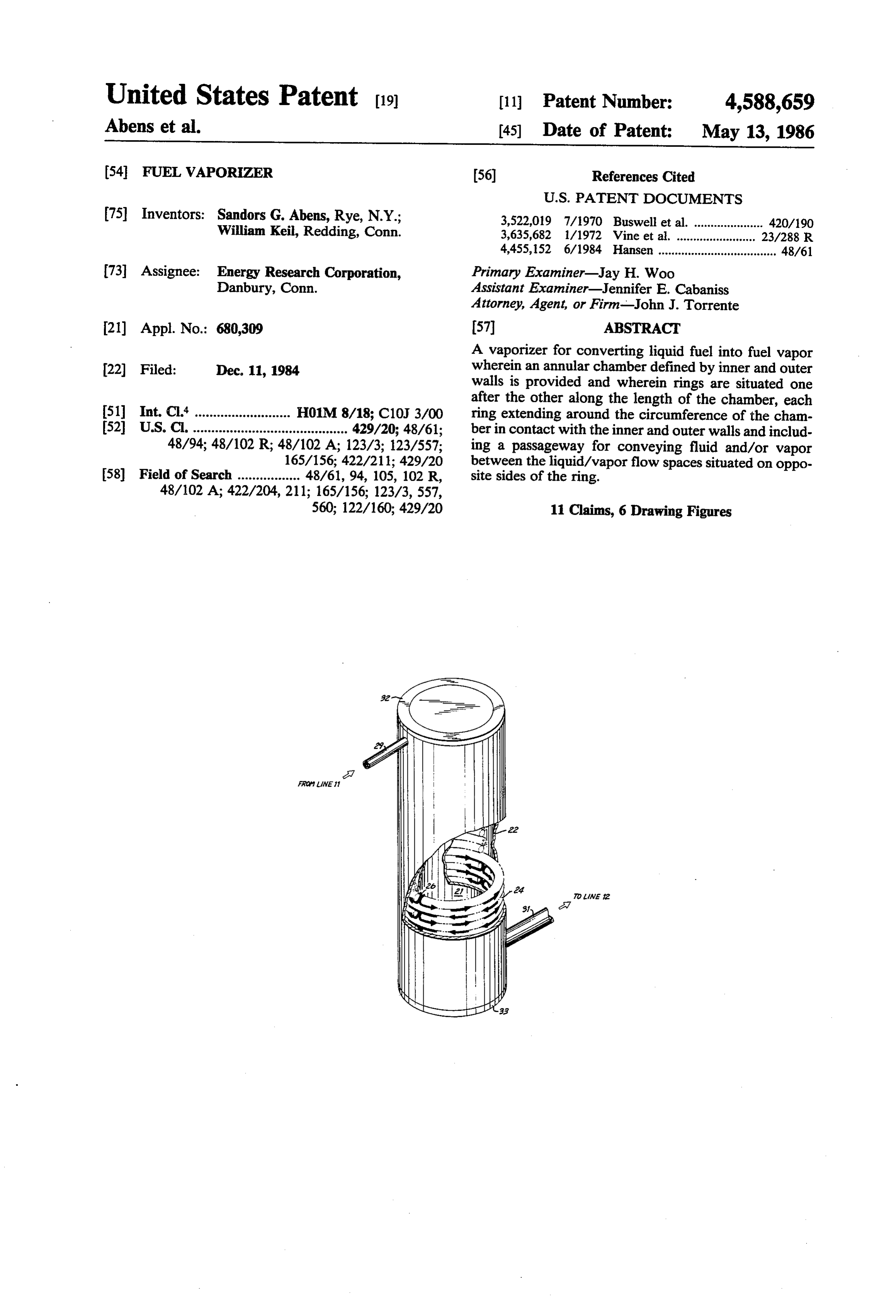
Attorney, Agent, or Firm--John J. Torrente 21) Appl. No.: 680,309 57 ABSTRACT A vaporizer for converting liquid fuel into fuel vapor 22) Filed: Dec. 11, 1984 wherein an annular chamber defined by inner and outer walls is provided and wherein rings are situated one after the other along the length of the chamber, each (51) Int. Cl." .......................... H01M 8/18; C10J 3/00 ring extending around the circumference of the cham (52) U.S. C. .......................................... 429/20: 48/61; ber in contact with the inner and outer walls and includ 48/94; 48/102 R; 48/102 A; 123/3; 123/557; ing a passageway for conveying fluid and/or vapor 165/156; 422/211; 429/20 between the liquid/vapor flow spaces situated on oppo 58) Field of Search ................. 48/61, 94, 105, 102 R, site sides of the ring.
560; 122/160; 429/20 11 Claims, 6 Drawing Figures
AME 2
Page 2
Drawing sheet — no readable text.
Page 3
Drawing sheet — no readable text.
Page 4
It is therefore an object of the present invention to
FUEL VAPORIZER provide a vaporizer for a fuel cell powerplant which is adapted to provide changes in output flow to accomo
BACKGROUND OF THE INVENTION date rapid changes in loading of the fuel cell. This invention relates to fuel vaporizers and, in par SUMMARY OF THE INVENTION ticular, to fuel vaporizers to be used in fuel conditioners In accordance with the principles of the present in for supplying fuel gas to fuel cell powerplants.
Fuel cell powerplants are similar to conventional vention, the above and other objectives are realized in a electric storage batteries in that, like electric storage fuel vaporizer comprising inner and outer walls which batteries, fuel cell powerplants produce electrial current O define therebetween an annular chamber and a plurality while consuming reacting chemicals at the powerplant of rings arranged one after the other along the chamber electrodes. In storage batteries, the reacting chemicals length, each ring having inner and outer surfaces in are included in the battery electrodes themselves, and contact with the inner and outer chamber walls, respec tively, and each ring further having a passage for pro no transport of reactants to the electrodes is required. In 15 viding communication between the liquid/vapor flow contrast, the electrodes in fuel cell powerplants are spaces situated inert, and the reactants must be transported to the elec sides of the ring.along the chamber length on opposite trodes from external sources.
Conventional types of fuel cell powerplants generally path With this type of configuration for the vaporizer, the employ gases as reactants. Air is usually used as the 20 spaces for the fuel fed into the vaporizer is confined to the cathode electrode reactant and hydrogen as the anode defined by the regions between the rings and the electrode reactant. The reactant hydrogen is commonly chamber result, a walls (i.e., the liquid/vapor flow spaces). As a fuel path of limited volume but extended sur derived by steam reforming a liquid or gaseous hydro face area is created carbon fuel. In this process the hydrocarbon fuel and results in an outputthrough fuel the vaporizer. This, in turn, vapor whose rate of flow can water are first vaporized and a mixture of the hydrocar 25 change rapidly in response to rapid changes in the rate bon vapor and water vapor is then passed over a hot of catalyst bed. The catalyst bed, in turn, converts the rapid changes in load when employed inaccomodate fuel input. The vaporizer can, therefore, a fuel cell mixture to hydrogen and carbon dioxide for use as the powerplant.
anode electrode reactant. A fuel cell powerplant will In the embodiment of the invention to be disclosed thus generally include, in addition to a fuel cell, a fuel 30 hereinafter, the inner and outer walls of the vaporizer conditioner provided with a vaporizer and with a re are cylindrical and the rings are of rounded configura forming catalyst bed for generating the anode or fuel tion. Furthermore, the passages in successive rings are reactant gas.
A requirement of fuel cell powerplants is that the rate through substantially thesoentire spaced 180 degrees apart as to force the flow of liquid of reactant flowing to the fuel cell electrodes be propor 35 ume defined by the rings and theliquid/vapor chamber flow vol walls. This tional to the current being drawn from the fuel cell. The ensures maximum contact with the volume surfaces reactant flow to the fuel cell is generally higher than the minimum rate predicted by Faraday's Law and, thus, all and, therefore, a maximum vaporization effect. the reactant is not used in the electrochemical reaction. BRIEF DESCRIPTION OF THE DRAWINGS In the case of the anode or fuel reactant, the excess fuel The above and other features and aspects of the pres not used for the electrochemical reaction is routed to a burner. The latter generates heat for the fuel vaporizer the invention ent will become more apparent upon reading following detailed description in conjunction with and the fuel reformer. For any given operating load the accompanying drawings, in which:
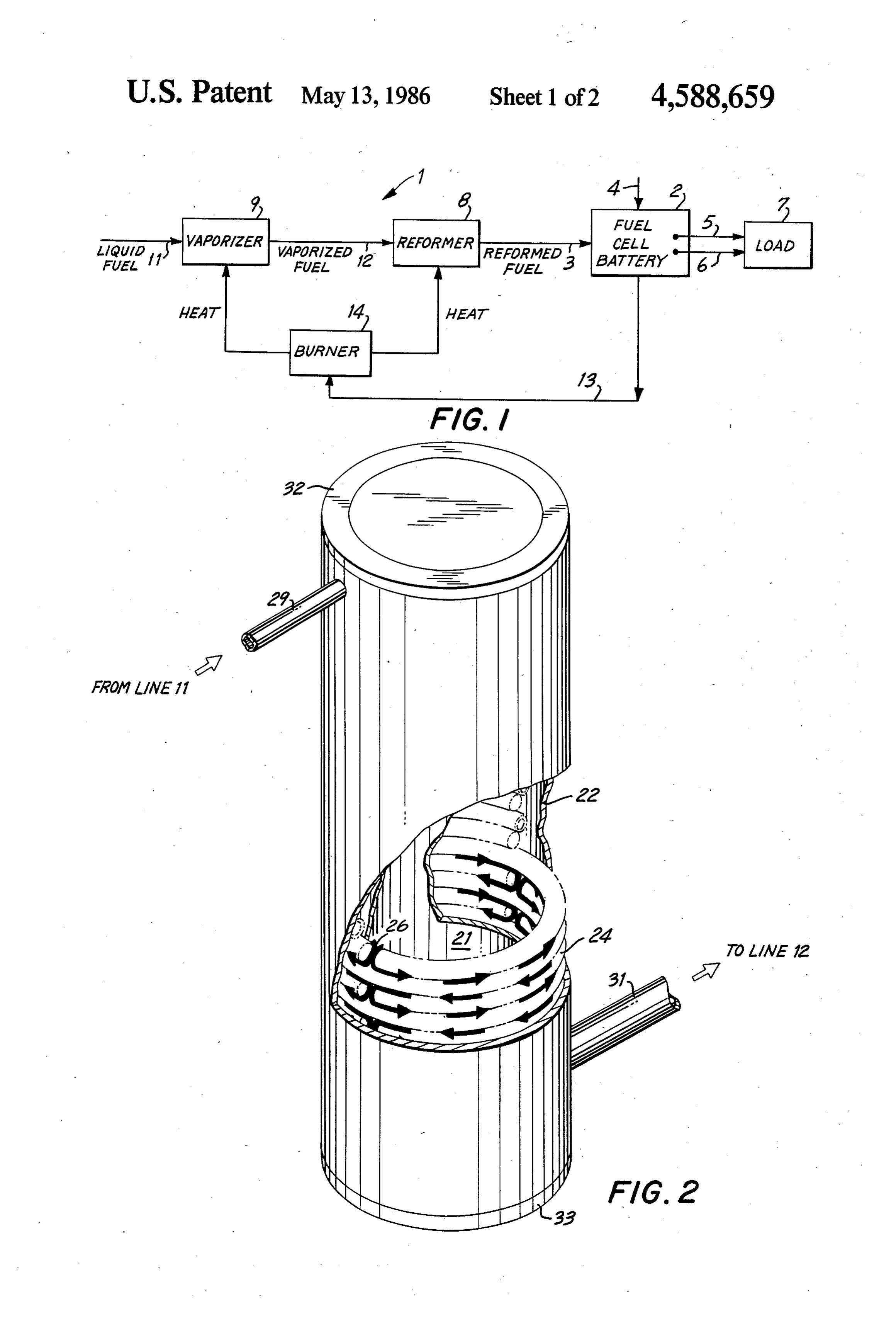
both the fuel cell and the burner fuel requirements are FIG. 1 shows a fuel cell powerplant utilizing a vapor fixed, thus fixing the rate of reformed fuel flow which 45 izer in accordance with the principles of the present must be delivered to the fuel cell from the fuel vaporizer invention;
and fuel reformer. FIG. 2 shows an isometric partially broken away As can be appreciated, when the operating load of the view of the fuel vaporizer of FIG. 1; fuel cell changes, the fuel requirements of the fuel cell FIG. 3 illustrates a cross-sectional view of the vapor and burner also change, thereby necessitating a change 50 izer of FIG. 2;
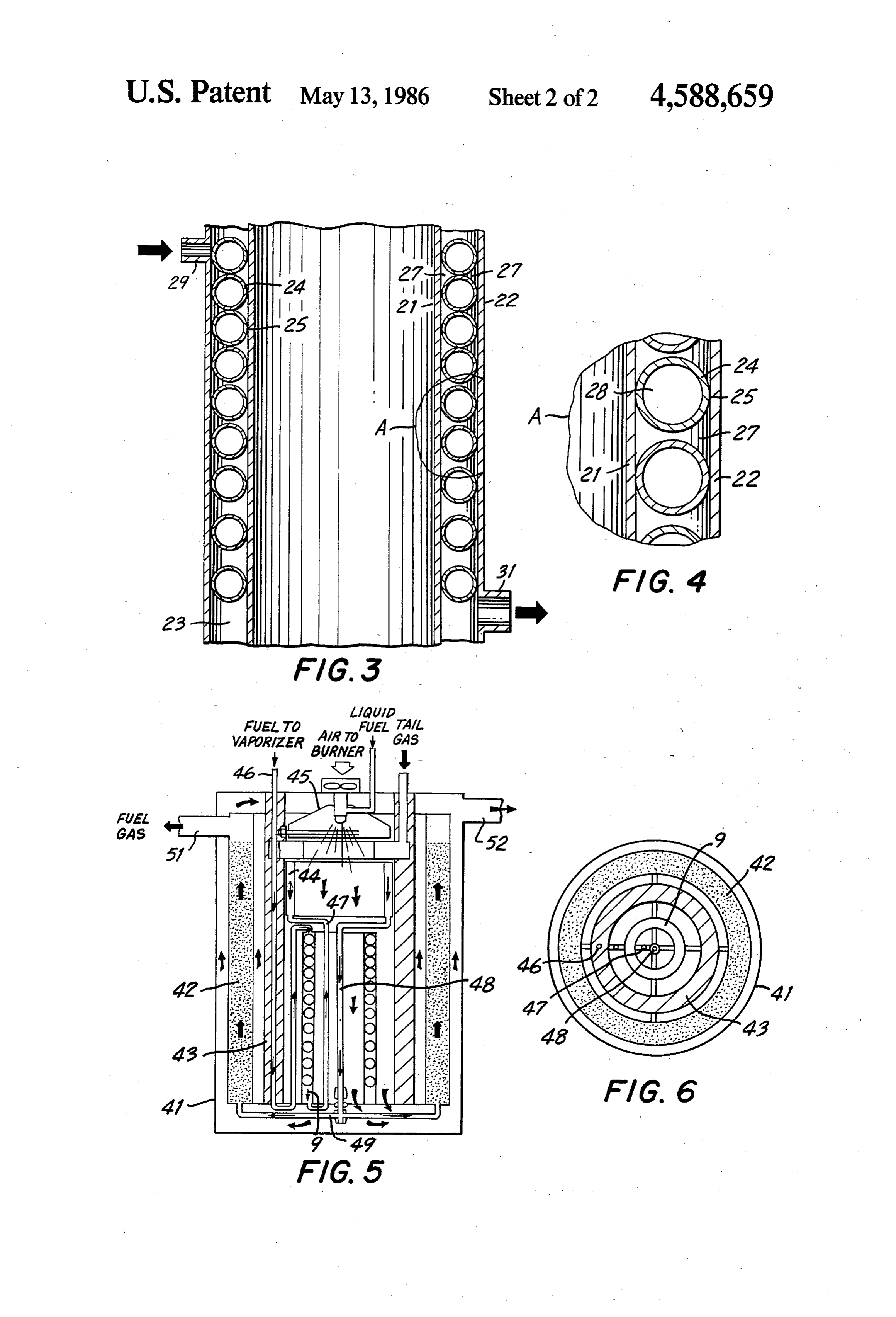
in fuel flow to the fuel cell in order to meet these FIG. 4 shows an exploded view of the circled region changed requirements. A change in fuel flow to the fuel A of the vaporizer cross-section of FIG. 3; cell requires that there be a corresponding change in FIG. 5 illustrates a cross-sectiontal view of the vapor output fuel flow of the fuel vaporizer. While conven izer of the invention incorporated into a fuel, reformer; tional vaporizers such as, for example, standard boilers, 55 and operate satisfactorly under constant output flow condi FIG. 6 illustrates a top view of the reformer of FIG. tions, such vaporizers do not function adequately where 1.
changes in output flow are required. This is especially true where the changes in output flow must be rapid to DETALED DESCRIPTION OF THE accomodate rapid load changes, particularly rapid in DRAWINGS creases in output electric load from low to high values. In FIG. 1, a fuel cell powerplant 1 comprises a fuel The inability of conventional boilers to rapidly vary cell 2 having anode and cathode electrode sections 2A output flow is caused primarily by the inertia of the and 2B (not visible). The electrode sections 2A and 2B boiler which delays production of vapor at the required are fed respectively input fuel gas from a fuel gas line 3 changed rate. This delay results in the depletion of 65 and input oxidant gas from an oxidant gas line 4. Elec gaseous fuel at the fuel cell which, in turn, causes a loss trochemical reaction of these gases in the cell results in of power and, thereby, decreased performance of the the production of electrical current which is fed over cell. lines 5 and 6 to a load 7.
Page 5
The fuel gas on line 3 is developed by a fuel reformer por flow space 27 and proceeds therethrough until the 8 and a fuel vaporizer 9. In particular, the vaporizer 9 flows join again at the corresponding passageway 26. receives hydrocarbon liquid fuel and water from a sup At this point, the combined flow passes through the ply line 11. The vaporizer, in turn, converts the liquid passageway 26 to the next liquid/vapor flow space 27 fuel and water to a vaporized or gaseous state and deliv where it again splits into two circumferential flows. ers the vaporized mixture to reformer 8 over line 12. These flows meet at the passageway 26 of this next In the reformer, the vaporized fuel and water vapor liquid/vapor flow space and, in turn, proceed to yet the mixture is passed over a catalyst bed. The catalyst con next liquid/vapor flow space 27 where the process is verts the mixture to hydrogen and carbon dioxide gas again repeated.
and this gas is then applied to the fuel cell anode elec O As the liquid is proceeding in this fashion, it is being trode by line 3. As above mentioned, the aforesaid ap continuously heated by the walls 21 and 22 which, in plied hydrogen gas and the oxidant gas supplied on line turn, are heated by hot gases generated by burner 14. 4 undergo electrochemical conversion in the cell to The liquid is thus continuously vaporized so that both produce electrical current on lines 5 and 6 for load 7. liquid and vapor traverse the liquid/vapor flow spaces Excess fuel gas not utilized in the electrochemical 15 27 and connecting passages 26. Finally a point is reaction is fed over line 13 to a burner 14 which burns reached along the chamber length at which all the liq the excessfuel to develop heat. This heat is then applied uid is vaporized and the resultant vapor continues to vaporizer 9 and reformer 8 to provide the heat en through the spaces and passageways and exits from the ergy for vaporization and reformation. outlet 31 as the desired gas vapor. As can be appreciated, variations or changes in the 20 As can be appreciated, the presence of the rings 24 in load 7 require corresponding changes in flow rate of the the chamber 23 creates a limited liquid/vapor flow fuel gas supplied to the fuel cell 2 from the line 3 in space or volume, while also creating an extended flow order to provide constant output power to the load. path which is closely adjacent the heated walls 21 and Changes in the flow rate of the fuel gas, in turn, are 22. As a result, the vaporizer 9 is able to respond sub generally effected by changing the flow rate of the 25 stantially instantaneously to changes in the flow rate of liquid fuel supplied on line 11 to the vaporizer 9. These fuel at the input 29. The output flow rate of vaporized changes are then reflected in the flow rate of fuel deliv fuel thus closely tracks the input flow rate of fuel so that ered by the vaporizer on line 2 to reformer 8 which, in there is no substantial loss in response. turn, provides a corresponding change in the fuel gas More particularly, an increase in the flow of liquid delivered on line 3 to the celi 2. 30 fuel at the input 29 of the vaporizer 9 is found to result In accordance with the principles of the present in in total vaporization of the fuel at a point further along vention, the vaporizer 9 is constructed such that its the length of the vaporizer path, rather than causing a output flow rate can change rapidly to follow rapid build-up or accumulation of fluid in the path. No sub changes in the liquid fuel flow online 11 associated with stantial inventory of fluid is thus created and the output rapid changes in the load 7. More specifically, the va 35 vapor flow rate is thus able to closely and rapidly fol porizer 9, as shown more clearly in FIGS. 2, 3 and 4, low the changes in input flow rate.
comprises an inner cylindrical wall 21 and an outer In order to ensure that the liquid introduced into the cylindrical wall 22 which together define an annular vaporizer 9 traverses a maximum flow path it is prefera chamber 23. Disposed within the chamber 23 and along ble that the rings 24 be arranged so that the passageway : the chamber length are rings 24 whose outer surfaces 25 26 in each succeeding ring is displaced circumferen contact the inner and an outer chamber walls 21 and 22. tially by approximately 80 degrees relative to the pas As shown in FIGS. 3 and 4, the rings 24 create a sageway 26 of the preceding ring. With this type of confined liquid/vapor flow space 27 closely adjacent configuration, the opposite circumferential flows will the chamber walls for passage of liquid and/or vapor each encompass substantially one-half the circumferen through the chamber. The space occupied by the rings, 45 tial length of each liquid/vapor flow space, thus maxi in turn, defines a liquid/vapor void space 28 since it mizing the length of path traveled. cannot be occupied by liquid and/or vapor. It should be noted that, as in the case of most liquids Each ring 24 extends substantially about the entire the hydrocarbon liquids applied to vaporizer 9 undergo circumference of the annular chamber 23 and is cut or a substantial increase in volume (e.g., an increase of interrupted at a point along its length to define a 50 1,000 or greater) upon conversion from liquid to vapor. through passage 26 (See, FIG. 2). Each passage 26 In order for the vaporizer 9 to accommodate this in allows communication between the liquid/vapor flow crease in volume in a manner which maintains a free space 27 immediately above and below its correspond flow of fluid and inhibits pressure drop, the rings 24 ing ring 24. may be selectively spaced by increasing amounts when An inlet tube 29 receives liquid fuel from the line 11 55 proceeding along the vaporizer length from inlet to and an outlet tube 31 delivers vaporized fuel gas to line outlet as can be seen in FIG. 3. 12. Annular covers 32 and 33 seal off the top and bot The rings 24 of the vaporizer 9 can be simply con tom of the annular chamber so as to confine the liquid structed from lengths of metal tubing which are bent and/or resultant vapor to the chamber. and cut to provide the split ring configuration. If the As shown, the rings 24 are of circular configuration, tubing is hollow, the ends of the tubing will have to be but in actual practice they may be squeezed slightly so sealed to prevent it from filling with fluid. as to take on an eliptical configuration. Of course other In FIGS. 5 and 6the vaporizer of FIGS. 2-4 has been configurations might also be employed. Likewise other incorporated into a conventional cylindrical fuel re than cylindrical configurations might also be employed former used in conjunction with a conventional burner. for the inner and outer walls 21 and 22. 65 More particularly, the reformer 8 comprises an en In practice, the fuel to be vaporized is applied from closed container 41 into which is concentrically line 11 to the inlet tube 29. The fluid then splits into mounted an annular catalyst chamber 42 and an annular opposite circumferential flows along the first liquid/va support cylinder 43. Concentrically disposed within the
Page 6
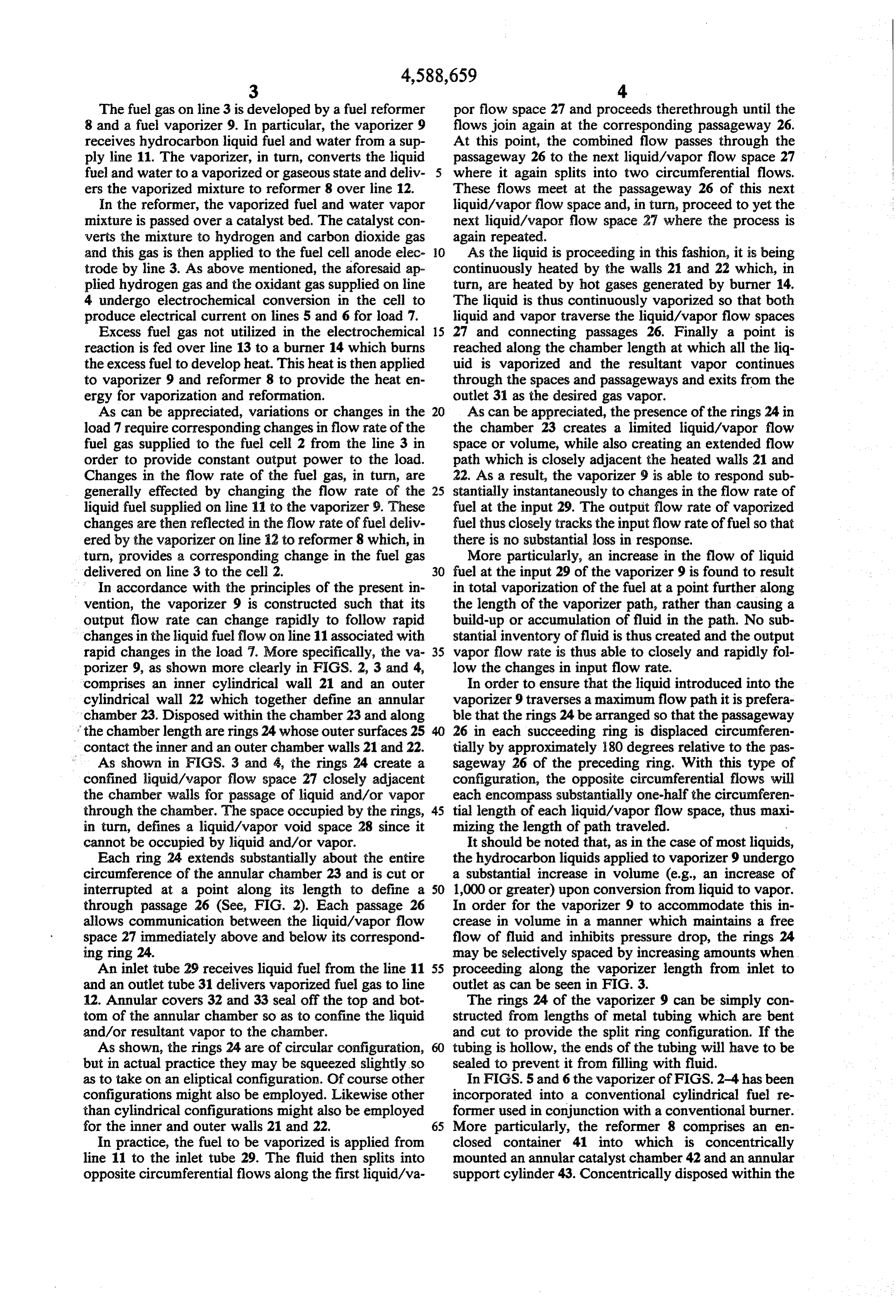
support cylinder 43 is a vaporizer 9 configured in accor- a plurality of rings situated in the chamber after the dance with the invention. other along the chamber length, each ring extend Mounted above the vaporizer 9 is a superheater ele- ing over the circumference of the chamber in ment 44 and a burner 45. Fuel for the vaporizer 9 is contact with said first and second walls, whereby carried by fuel line 46 which is supported in the wall of 5 said rings and walls define flow spaces for passage cylinder 43. Vapor output of the vaporizer is carried by of fluid through said vaporizer, each ring having a the line 47 to the superheater 44 and carried from the passageway for enabling communication of the superheater output via lines 48 and 49 to the input to the flow spaces on opposite sides of the ring. annular catalyst chamber 42. The resultant reactant gas 2. A vaporizer in accordance with claim 1 wherein: is coupled via port 51 out of the catalyst chamber. 10 the passageway of each ring is displaced circumferen In operation, fuel to be vaporized is applied to fuel tially by 180 degrees relative to the passageways of line 46 and carried by the line to the annular chamber of the immediately adjacent rings. vaporizer 9. Heated air developed by the burner 45 3. A vaporizer in accordance with claim 2 wherein: passes down along the exterior of the inner and outer 15 the annular chamber has an inlet for receiving liquid cylinder walls of the vaporizer 9 heating same and, fuel and an outlet for conveying exiting vaporized therefore, the liquid fuel passing therethrough. fuel;
The liquid fuel is thereby vaporized and the vapor and the spacing between the rings along the length of ized fuel is passed from the vaporizer, via line 47, to the the chamber is greater for rings closer to the outlet superheater 44. After further heating, the vaporized fuel 20 relative to rings closer to the inlet. 4. A vaporizer in accordance with claim 3 wherein:
is carried from the superheater via lines 48 and 49 said first and second walls are of cylindrical configu through the catalyst bed 42. The bed 42 is also heated ration.
by the burner air which passes upwardly adjacent the 5. Apparatus comprising, in combination; catalyst bed walls after passing downwardly along the a vaporizer for converting liquid fuel to fuel vapor vaporizer walls. The vaporized fuel is converted by the 25 including: a first wall surrounded by a second wall catalyst bed into fuel gas and conveyed to port 51 for defining therebetween an annular chamber; a plu passage out of the reformer. The burner air exits the rality of rings situated in the chamber one after the container 41 through a flue exhaust 52. other along the chamber length, each ring extend A fuel vaporizer as shown in FIG. 2 was constructed ing over the circumference of the chamber in in the manner shown in FIGS. 3 and 4. The vaporizer 30 contact with said first and second walls, whereby cylindrical walls 21 and 22 were 8 inches high and fabri- said rings and walls define flow spaces for passage cated from steel tubing having a wall thickness of 1/16 of fluid through said vaporizer, each ring having a inch. The diameters of the inner and outer cylindrical passageway for enabling communication of the walls was 2 and 33 inches, respectively. The rings 24 flow spaces on opposite sides of the ring; an inlet were fabricated from inch tubing. 35 for delivering liquid fuel to said annular chamber; The vaporizer was tested as an integral part of a and an outlet for extracting fuel vapor from said methanol steam reformer having a configuration as chamber;
shown in FIG. 5 and operating on fuel comprising 58% a fuel reformer including a catalyst receiving said methanol and 42% water by weight. The reforming extracted fuel vapor and converting said fuel vapor catalyst comprised copper-zinc oxide and was con- to fuel gas. o tained in an annular chamber surrounding the vapor- 6. Apparatus in accordance with claim 5 further in izer. The reformer output was then applied to a fuel cluding a fuel cell having an anode section for receiving cell. said fuel gas.
With this configuration, the vaporizer was found to 45 Apparatus in accordance with claim 6 further in satisfactorily follow step variations in output load. In particular, a stepwise load increase from a fuel con a burner for generating heat for said vaporizer and fuel reformer.
sumption rate of 35 ml/min at hot idle operation to a 8. Apparatus in accordance with claim 7 wherein: rate of 70 ml/min at rated power operation was realized said,burner receives fuel vapor exhausted from said without interruption or diminishing of the power output 50 fuel cell.
to the electrical load.
In all cases, it is understood that the above-described 9. Apparatus in accordance with claim 6 wherein: said fuel reformer is a steam reformer and includes a arrangements are merely illustrative of the many possi catalyst for converting hydrocarbon fuel vapor to ble specific embodiments which represent applications hydrogen gas.
of the present invention. Numerous and varied other 5s 10. Apparatus in accordance with claim 9 wherein: arrangements can readily be devised in accordance with said steam reformer comprises an annular chamber in the principles of the present invention without depart- surrounding relationship to said first and second ing from the spirit and scope of the invention. walls of said vaporizer containing said catalyst. What is claimed is: 11. Apparatus in accordance with claim 10 further 1. A vaporizer for converting liquid fuel to fuel vapor 60 comprising:
comprising: means for heating said annular chambers of said va a first wall surrounded by a second wall defining porizer and said steam reformer. therebetween an annular chamber; k . . k is
Page 7
UNITED STATES PATENT AND TRADEMARK OFFICE
CERTIFICATE OF CORRECTION
NVENTOR(S) : Sandors G. Abens and William Keil it is certified that error appears in the above-identified patent and that said Letters Patent is hereby Corrected as shown below:
Column l, Before "BACKGROUND OF THE INVENTION" add the following:
GOVERNMENT INTERESTS
The invention described herein may be manufactured, used and licensed by or for the United States Government for governmental purposes without the payment of any royalties thereon. The invention herein evolved out of Government Contract Number DAAK 70-79-C-0249 by and between the U.S. Army and Energy Research Corporation.
Signed and Sealed this
Third Day of March, 1987
Attest:
DONALD J. QUIGG
Attesting Officer Commissioner of Patents and Trademarks
Provenance
- Collection
- Cited prior art
- Original PDF
- patentimages.storage.googleapis.com →
- Filed
- 1984-12-11
- Pages
- 7
- Method
- pdftotext (the PDF's own text layer) + pdftoppm 300dpi page scans
- Source
- Google Patents bibliographic record
- Granted
- 1986-05-13
- Inventors
- Sandors G. Abens; William Keil; Energy Research Corp
- Transcribed from
- patentimages.storage.googleapis.com →