patent · US5092304
Mounted fuel tank heater
3 March 1992
Page 1 — bibliographic record
United States Patent 19) 11) Patent Number: 5,092,304
McNelley (45. Date of Patent: Mar. 3, 1992 54 MOUNTED FUELTANK HEATER 4,748,960 6/1988 Wolf.................................... 123/557 4,865,005 9/1989 Griffith ........................ ... 123/557 76 Inventor: Jerald R. McNelley, Rte. 2, Box 172,
Benton, Tenn. 37307 FOREIGN PATENT DOCUMENTS
The portion of the term of this patent WO89/07791 8/1989 World Int. Prop. O. ............ 65/35 subsequent to May 22, 2007 has been Primary Examiner-John Ford disclaimed. Attorney, Agent, or Firm-Pitts and Brittian 21 Appl. No.: 495,778 57 ABSTRACT 22 Filed: Mar. 19, 1990 A system (10) for preheating fuel in a fuel tank (16) for an internal combustion engine. The system (10) includes
Related U.S. Application Data a heat exchanger (12) for transferring heat from a 63 Continuation-in- f Ser. No. 306,641, Feb. 3, 1989, heated fluid to the fuel. The heat exchanger (12) in 63 E" of Ser. No e cludes a fuel tube (32) being surrounded by the heated fluid for further heating of the fuel prior to its entering 51 Int. Cl...................... F02M 53/00; FO2M 31/16; the fuel line of the vehicle or other device in which the FO2N 17/02 system is installed. In the preferred embodiment, the 52 U.S. Cl. ............................. 123/557; 123/42.5 R; heat exchanger (12) is installed through an access open 123/549; 165/51; 165/41; 165/74; 165/142 ing (14) normally provided in fuel tanks used in diesel 58) Field of Search ..................... 123/557, 142.5, 549; engine-powered over-the-road trucks. A flange (18) is 65/35, 51, 41, 74, 142 provided for securing the heat exchanger (12) to the (56. References Cited flange (20) which surrounds the opening (14) in the fuel
4,684,786 8/1987 Mann et al. ......................... 123/557 6 Claims, 4 Drawing Sheets
Page 2
Drawing sheet — no readable text.
Page 3
Drawing sheet — no readable text.
Page 4
Drawing sheet — no readable text.
Page 5
Drawing sheet — no readable text.
Page 6
low profile and occupy the minimum amount of space
MOUNTED FUELTANK HEATER exterior of the fuel tank.
DESCRIPTION DISCLOSURE OF THE INVENTION
This is a continuation-in-part application based upon Other objects and advantages will be accomplished application Ser. No. 7/306,641, filed Feb. 3, 1989, now by the present invention which provides a system for U.S. Pat. No. 4,926,830 issued May 22, 1990. preheating fuel for an internal combustion engine in the 1. Technical Field fuel tank normally provided with the vehicle or other This invention relates to a system for preheating fuel device powered by such engine. The system includes a for an internal combustion engine in the fuel tank nor 10 heat exchanger which is installed in the fuel tank of the mally provided with a vehicle or other machine pow vehicle or other device. In the preferred embodiment, ered by such engine. the heat exchanger is installed through and secured to 2. Background Art the opening normally provided in the fuel tanks of most It is well known that preheating the fuel used in an diesel engine-powered over-the-road trucks for installa internal combustion engine improves the efficiency of 15 tion of a fuel gauge. Most such trucks are provided with the engine. Further, preheating the fuel typically used two fuel tanks and the fuel gauge access opening is in a diesel engine can avoid serious fuel flow problems usually only used for a fuel gauge in one of the tanks. well known to occur in cold weather environments. Therefore the unused opening in one of the tanks can be Diesel fuel, and in particular the No. 2 fuel oil typi used for installation of the present invention. cally burned by the engines of over-the-road trucks, can 20 In the preferred embodiment, the heat exchanger is congeal or "wax' in the cold weather regularly experi an elongated substantially cylindrically shaped device enced during the winter months in the northern states of made of a thermally conductive material, preferably a the United States and in Canada. The jelling or waxing corrosion-resistant metal. The heat exchanger includes of fuel can shut a diesel engine down, necessitating the a heated fluid chamber and a fuel tube, ending in a towing of the vehicle to a repair facility where the fuel 25 ninety degree elbow, extending through such chamber. tank must be heated to alleviate the problem. The ex The heated fluid chamber includes an inlet port and an pense of towing and downtime can be substantial. outlet port positioned in a first end portion of the heat A number of methods and devices have been devel oped in an attempt to solve the problem of congealing exchanger. A divider plate is provided in the heated fuel oil in cold weather. One method has been to install 30 fluid chamber between the inlet and outlet port which a heater in the fuel line. U.S. Pat. No. 3,929, 187 dis extends from the first end portion of the chamber closes a device which utilizes this method. However, through all but a small portion of the length of the this method does not solve the problem of fuel oil con chamber. The divider plate divides the heated fluid gealing within the fuel tank itself before it even gets into chamber into an inlet section and an outlet section the fuel line. Another method is to install a heater in the 35 whereby heated fluid from an external source enters fuel tank. U.S. Pat. No. 4,237,850 discloses a device through the inlet port and travels through the inlet which utilizes this second method. The device disclosed section toward the second end portion of the chamber in this patent has two primary disadvantages. One, where it passes into the outlet section and travels back while the fuel can be heated in the tank to a temperature toward the first end portion where it exits through the above that at which it "waxes', it is not necessarily outlet port and is returned to the external source for heated to a temperature which will prevent it from reheating. Heat is transferred through the external walls congealing in the fuel line in extremely cold weather, of the heat exchanger from the heated fluid to the fuel because of the volume of fuel which must be heated in in the fuel tank.
the tank which is usually directly exposed to the cold As indicated above, a fuel tube with a ninety degree outside air temperatures. Second, the device disclosed 45 elbow termination is provided which extends through, in this patent requires an access opening which must be and is therefore surrounded by, the heated fluid cham cut/formed into the top of the fuel tank prior to installa ber. In the preferred embodiment, fuel is drawn into an tion of the device. open fuel inlet end of the tube proximate and external to Therefore, it is a principal object of the present inven the second end portion of the heat exchanger, and is tion to provide a system for preheating diesel fuel in the 50 drawn through the fuel tube where it is further heated fuel tank to a temperature above that at which the fuel by the heated fluid in the above-described chamber would normally congeal. which surrounds the fuel tube, and exits from the fuel It is a further object of the present invention to pro outlet ninety degree elbow end of the tube which is vide a system for preheating the diesel fuel leaving the connected to the fuel line of the vehicle in which the fuel tank to a temperature which is sufficiently higher 55 present invention is installed, proximate and external to than the temperature at which the fuel would normally the first end portion of the heat exchanger. congeal such that the fuel cannot jell in the fuel line In the preferred embodiment, the external source of between the fuel tank and the diesel engine to which it heated fluid is the radiator of the vehicle in which the is supplied. present invention is installed. Fluid communication can It is yet another object of the present invention to be provided between the radiator and the inlet and provide a system for preheating the fuel in the fuel tank outlet ports of the above-described heated fluid cham of a diesel engine-powered vehicle or machine which ber via flexible hoses similar to those normally used in includes a heat exchanger which can be installed internal combustion engines to provide fluid communi through and secured in the opening normally provided cation between the radiator and the engine block. In in such a fuel tank for the installation of a fuel level 65 another embodiment of the present invention, the galge. heated fluid can comprise lubricating oil circulated It is another object of the present to provide such a from the oil pan of the engine with which the system is diesel fuel tank heater in a form designed to present a used.
Page 7
Fuel is drawn from the fuel tank through the ninety small portion of the length of the heat exchanger 12 degree elbow end of the fuel tube of the present inven where it terminates in a distal end portion 42, such that tion into the fuel line as described above by the fuel fluid communication is provided between the inlet sec pump of the engine of the vehicle or other device in tion 36 and the outlet section 38 of the heated fluid which the system is installed. chamber 26 proximate the second end portion 34 of the
BRIEF DESCRIPTION OF THE DRAWINGS
heat exchanger.
Referring to FIG. 1 and to FIG. 4, which is a block
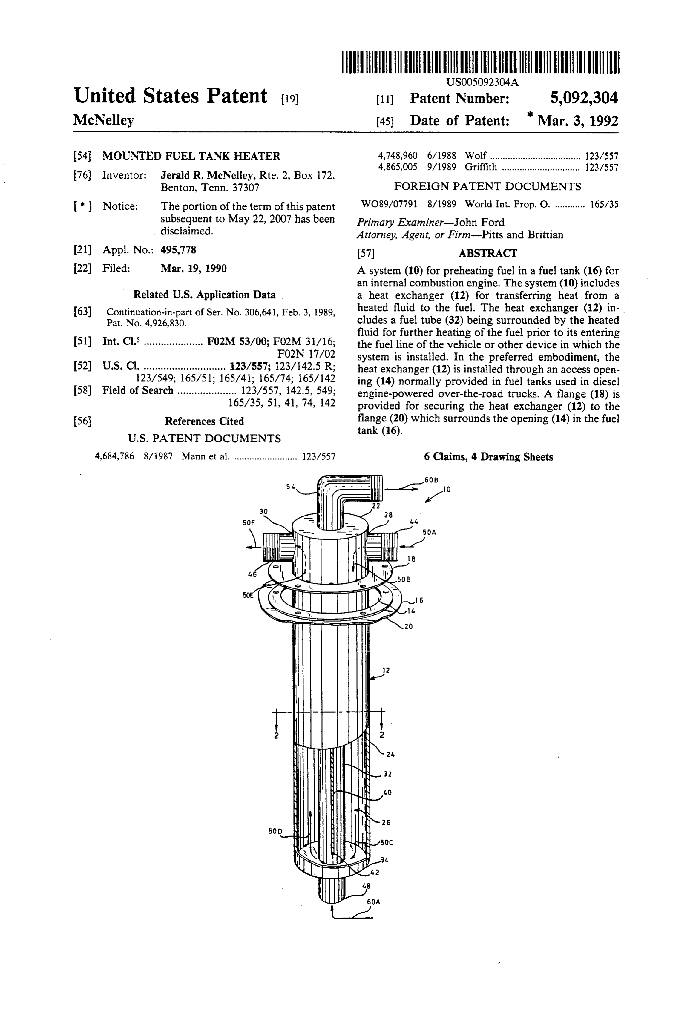
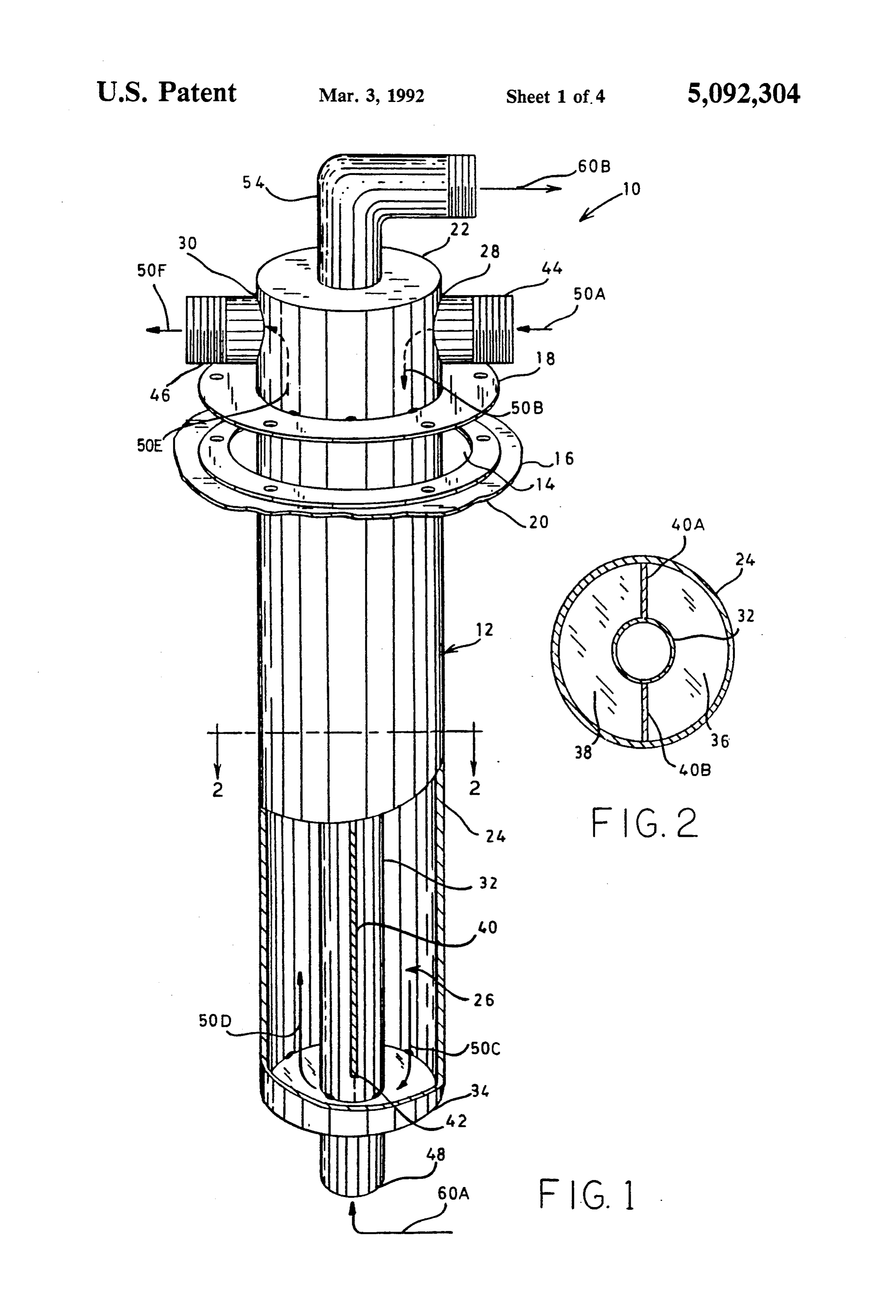
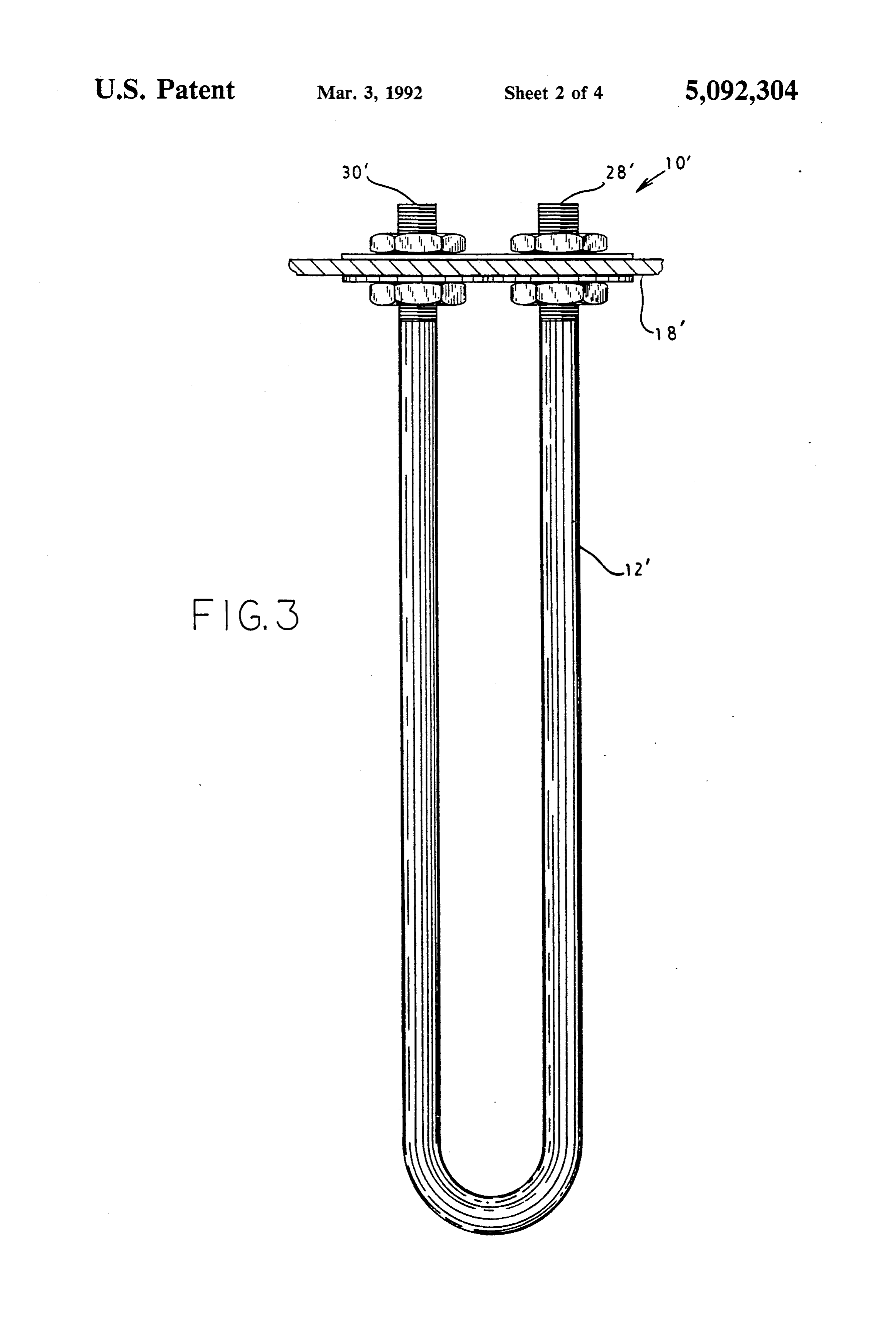
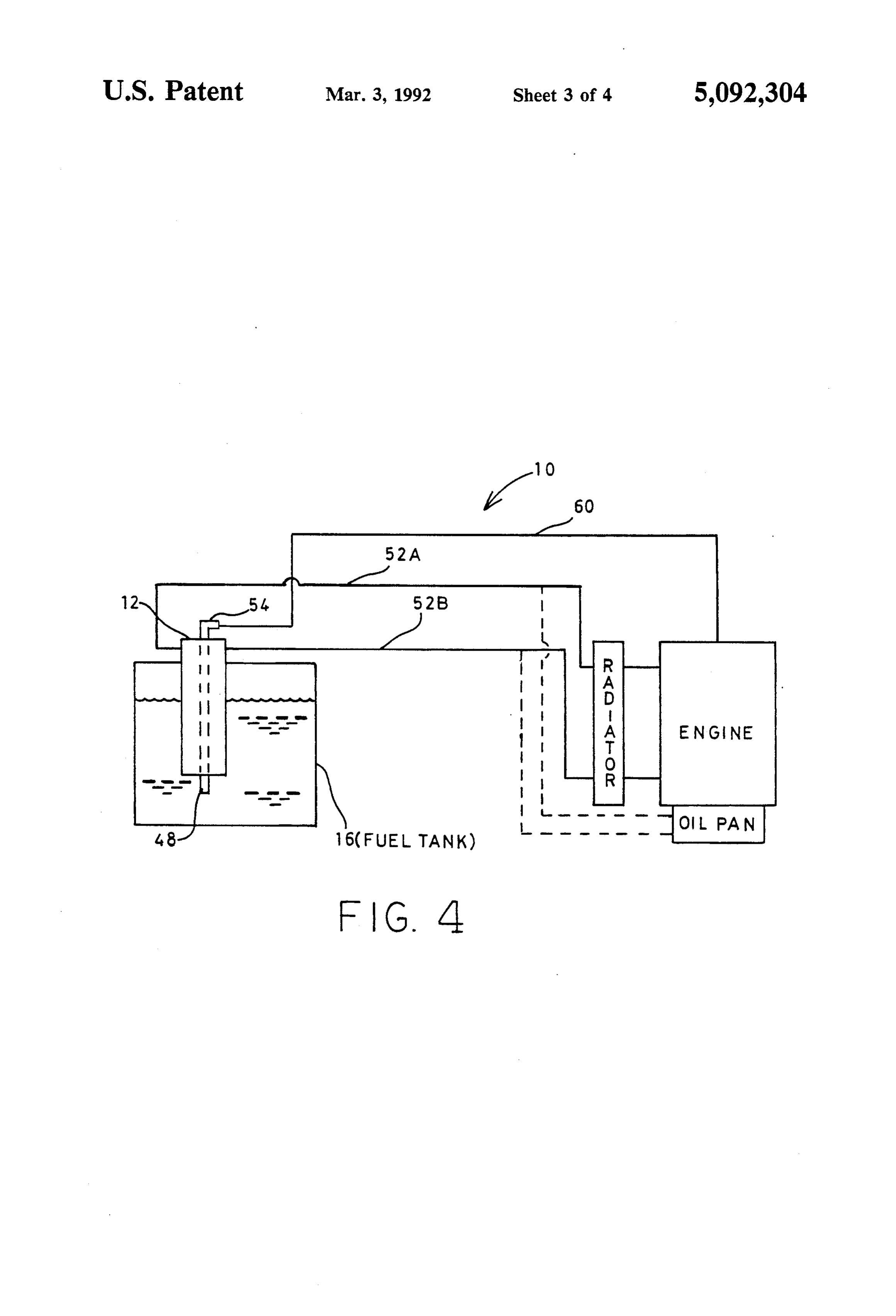
FIG. 1 illustrates a perspective view, partially cut diagram of the system 10, it can be seen that heated fluid away, of a system for preheating fuel for an internal enters via an appropriate fitting 44 into the inlet port 28 combustion engine in a fuel tank constructed in accor O of the heat exchanger 12, as indicated by the arrows dance with various features of the present invention. 50A and 50B. The heated fluid travels down through FIG. 2 illustrates a top view in section of the heat the inlet section 36 of the heated fluid chamber 26 and exchanger, taken at 2-2 of FIG. 1, of a system for under the distal end portion 42 of the divider plate 40 preheating fuel for an internal combustion engine con into the outlet section 38 of the heated fluid, chamber structed in accordance with various features of the 5 26, as indicated by the arrows 50B, 50C, and 50D. The present invention. heated fluid exits the outlet section 38 of the chamber 26 FIG. 3 illustrates a front elevation view of an alter through the outlet port 30 via an appropriate fitting 46, nate embodiment of a system for preheating fuel for an as indicated by the arrows 50E and 50F. It will be ap internal combustion engine in a fuel tank constructed in preciated by those skilled in the art that heat from the accordance with various features of the present inven 20 heated fluid will be transferred to the fuel in the fuel tion. tank which surrounds the heat exchanger 12, which FIG. 4 illustrates a block diagram of a system for preferably is constructed of a corrosion-resistant metal preheating fuel for an internal combustion engine in a which has good thermal conductivity. In the preferred fuel tank constructed in accordance with various fea embodiment, the heated fluid comprises heated coolant tures of the present invention as illustrated in FIGS. 1 25 supplied from and returned to the radiator of the vehi and 2. cle or other device in which the system 10 is installed as FIG. 5 illustrates a perspective view, partially cut illustrated by the block diagram illustrated by FIG. 4. It away, of another embodiment of a system for preheat will be appreciated by those skilled in the art that fluid ing fuel for an internal combustion engine in accordance communication can be provided between the radiator with various features of the present invention. 30 and the inlet and outlet port fittings, 44 and 46 respec BEST MODE FOR CARRYING OUT THE tively, by hoses, indicated by the reference numerals INVENTION 52A and 52B in FIG. 4, similar to those typically used between a radiator and the block of an internal combus
A system for preheating fuel for an internal combus tion engine. Also, as indicated with dashed lines in FIG. tion engine in the fuel tank normally provided with the 35 4, the hoses 52A and 52B could be alternatively con vehicle or other device powered by such engine is illus nected to the oil pan of the internal combustion engine trated generally at 10 in FIG. 1. The system includes a for the circulation of lubricating oil as the heated fluid heat exchanger shown generally at 12 in FIG. 1. The for the heating of the fuel.
heat exchanger 12 is installed through an access opening Still referring to FIGS. 1 and 4, it can be seen that 14 which is normally provided in fuel tanks for diesel 40 fuel from the fuel tank enters the fuel tube 32 through engine-powered over-the-road trucks for installation of the open fuel inlet end 48 of the tube 32, as indicated by a fuel gauge. A portion of such a fuel tank is illustrated the arrow 60A, and exits through the fuel outlet ninety at 16 in FIG. 1. The heat exchanger 12 is provided with degree elbow end 54 of the tube 32, proximate and a flange 18, which is dimensioned and predrilled to externally of the first end portion 22 of the heat ex match the flange 20 surrounding the opening 14 in the 45 changer 12, as indicated by the arrow 60B. The ninety fuel tank 16, proximate a first end portion 22 of the heat degree elbow outlet end 54 of the fuel tube 32 communi exchanger 12. When the system 10 is installed, an appro cates with the fuel line, indicated by the line 60 in the priate gasket or seal (not shown) is installed between the block diagram illustrated in FIG. 4, which supplies fuel flange 18 and the flange 20. to the engine. It will be appreciated by those skilled in The heat exchanger 12 comprises a substantially cy 50 the art that the fuel entering the fuel line will have been lindrical vessel having an outer wall 24 which defines an further heated in the fuel tube 32 by the heated fluid in interior heated fluid chamber 26. An inlet port 28 and an the chamber 26 which surrounds the tube 32. outlet port 30 are provided proximate the first end por Referring to FIG. 3, an alternate embodiment 10' of tion 22 of the heat exchanger 12, between the first end the system of the present invention is illustrated. In the portion 22 and the flange 18, through which a heated 55 system 10, the heat exchanger 12" comprises a U-shaped fluid is supplied from and returned to an external source tube secured proximate its inlet and outlet openings, 28' of the heated fluid. A fuel tube 32 extends axially and 30', respectively, to a flange 18' which may be through the heat exchanger 12 from externally of its secured to a fuel tank 16 in a manner similar to that second end portion 34 to externally of its first end por described for the system 10 illustrated in FIGS. 1, 2, and tion 22. The fuel tube 32 is surrounded by the heated 4.
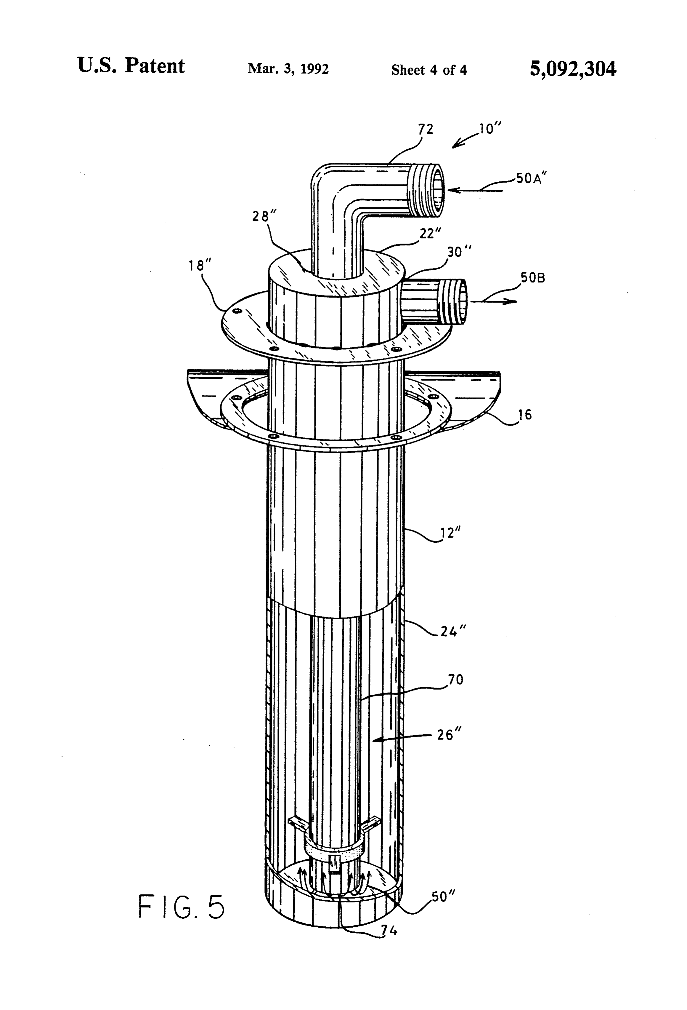
fluid chamber 26 as shown in FIGS. 1 and 2. The heated At 10' of FIG. 5, another alternate embodiment of fluid chamber 26 is divided into an inlet section 36 and the system of the present invention is illustrated. In the an outlet section 38, as illustrated in FIG. 2, by a divider system 10", the heat exchanger 12' comprises an elon plate 40, comprised of two coplanar plate sections 40A gated substantially cylindrical vessel having a similar and 40B positioned between the fuel tube 32 and the 65 overall external appearance to the heat exchanger 12 of outer wall 24 of the heat exchanger 12. The divider the system 10 illustrated in FIG. 1. However, in this plate 40 extends from the first end portion 22 of the heat embodiment, there is no fuel tube extending through the exchanger 12, parallel to the fuel tube 32, for all but a heat exchanger 12" as in the system 10; in this system
Page 8
10", fuel is drawn from the bottom of the fuel tank in the the fuel tank 16. The fuel is further heated by the heated conventional manner, i.e., fuel line connections in the fluid as it is drawn through the fuel tube 32 into the fuel vehicle or other device in which the system is used are line 60.
left undisturbed. The heat exchanger 12" defines a Accordingly, when the system 10 is installed in a heated fluid chamber 26' and includes a heated fluid vehicle or other device powered by an internal combus inlet port 28' positioned coaxially with the longitudinal tion engine, the efficiency of such engine will be im axis of the heat exchanger 12" in the first end portion proved. In particular, the system 10 will eliminate or 22' of the heat exchanger. A heated fluid inlet tube 70 minimize the problem of congealing or "waxing' of is provided which extends coaxially through the heat diesel fuel in a diesel engine-powered vehicle or other exchanger 12" from a ninety degree elbow inlet end 72, 10 device operated in cold weather environments. positioned externally of and proximate the first end While a preferred embodiment has been shown and portion 22' of the heat exchanger 12', through the inlet described, it will be understood that it is not intended to port 28", to an open outlet end 74 positioned within the limit the invention to such disclosure, but rather it is heated fluid chamber 26" proximate the second end intended to cover all modifications and alternate con portion 34" of the heat exchanger, such that heated fluid 15 structions falling within the scope of the invention as in the inlet tube 70 flows into the heated fluid chamber defined in the appended claims. 26", as indicated by the arrows 50". In this embodiment, I claim:
heated fluid from an external source (as described above 1. A system for preheating fuel for an internal com for the system 10) enters the ninety degree elbow inlet bustion engine having a fuel line comprising: end 72 of the inlet tube 70, flows down through the tube 20 a fuel tank for storing fuel to be supplied to said fuel 70 and out of the outlet end 74 into the chamber 26' line, said tank having an access opening provided proximate the second end portion 34" of the heat ex in an upper portion thereof; changer 12", and back toward the first end portion 22' an elongated heat exchanger installed through and of the heat exchanger where it exits through the outlet secured to said access opening, a substantial por port 30", as indicated by the arrows 50A", 50", and 25 tion of said heat exchanger being contained within 50B'. The heat exchanger 12" includes a flange 18" said fuel tank;
which may be secured to a fuel tank 16 in a manner said heat exchanger defining an inlet port and an similar to that described for the system 10 illustrated in outlet port proximate a first end portion of said FIG. 1. It will be appreciated by those skilled in the art heat exchanger positioned externally of said fuel that, because of the flow path of the heated fluid, the 30 tank;
greatest heat transfer from the heated fluid to the fuel in a heated fluid chamber defined by said heat ex the fuel tank will occur near the second end portion 34' changer communicating between said inlet and of the heat exchanger 12'. Since the heat exchanger is outlet ports, said heated fluid chamber including a installed through an opening normally provided in the divider plate which separates said heated fluid top portion of the fuel tank, the second end portion 34' 35 chamber into an inlet section communicating with of the heat exchanger will be positioned near the bottom said inlet port and an outlet section communicating of the fuel tank from which fuel is drawn into the fuel with said outlet port, said divider plate being posi line. Therefore, heating of the fuel entering the fuel line tioned such that a heated fluid entering said inlet is enhanced. This embodiment of the present invention port flows toward a second end portion of said heat also has the advantage of having improved heat transfer exchanger where said heated fluid flows through characteristics over prior art systems which utilize a said outlet section of said heated fluid chamber and U-shaped tube heat exchanger similar to that shown in exits through said outlet port; the system 10' illustrated in FIG. 3. Heat transfer from a source of said heated fluid; the heated fluid to the fuel in the fuel tank is increased means for providing fluid communication between because of the relatively large surface area provided by 45 said source of heated fluid and said inlet and outlet the external walls 24 of the heat exchanger 12" as com ports of said heat exchanger; pared to the U-shaped tube devices. said heat exchanger further comprising a fuel tube The right angle or ninety degree elbow feature 54 of passing substantially axially through said heated fuel tube 32, or 72 of heated fluid tube 70, of the above fluid chamber and forming a portion of said divider described heat exchanger embodiments 12 or 12", in 50 plate, said fuel tube having a fuel inlet end posi stead of ending in a straight fitting that extends at a right tioned externally of said heated fluid chamber angle to the heated fluid inlet ports 44 or 30", provides proximate said second end portion of said heat a fuel hose connection point which is parallel with that exchanger in fluid connunication with said fuel in of the heated fluid hoses and inlet ports 44 and 30'. This said fuel tank, and said fuel tubehaving a fuel outlet elbow joint provision allows connecting hoses to be 55 end with a ninety degree elbow positioned exter more conveniently attached and consume less space nally of said heated fluid chamber proximate said within the confines of the host vehicle. By providing first end portion of said heat exchanger in fluid the invention with fuel tube 32 already formed into an communication with said fuel line of said internal elbow joint, the necessity for later attachment of a combustion engine;
ninety degree adapter, with attendant possibilities for whereby said heat exchanger exhibits a low profile leakage, is eliminated. and occupies a minimal amount of space external of In light of the foregoing, it can be seen that a system said fuel tank;
10 is provided by the present invention for preheating whereby said fuel in said fuel tank is heated by heat the fuel for an internal combustion engine in the fuel transferred from heated fluid contained within said tank 16 by a heat exchanger 12 installed through an 65 heated fluid chamber through the walls of said heat access opening 14 in the fuel tank. Heat from a heated exchanger; and fluid which is supplied to the heat exchanger 12, as whereby fuel drawn from said fuel tank through said indicated by the arrows 50, is transferred to the fuel in fuel tube into said fuel line is further heated by heat
Page 9
transferred from heated fluid contained by said end formed into a bend of substantially ninety de heated fluid chamber which surrounds said fuel grees from the body of said fuel tube proximate tube.
2. The system of claim 1 wherein said source of said top closure for connection with said fuel line; a pair of oppositely disposed divider plates disposed heated fluid comprises a radiator containing a coolant 5 axially within said shell member extending from which communicates with a block of said internal con said top closure to a distal end positioned near said bustion engine for cooling said engine. bottom closure, said divider plates attached to and 3. The system of claim 1 wherein said source of extending radially to said fuel tube and further heated fluid comprises an oil pan of said internal com attached to said top closure, said divider plates bustion engine. 10 forming an inlet portion within said shell member 4. A system for preheating fuel for an internal com communicating with said inlet port and an outlet bustion engine of a vehicle having a fuel line, said vehi portion within said shell member communicating cle being equipped with a fuel tank for storing fuel to be with said outlet port, said inlet portion and said supplied to said fuel line, said fuel tank provided with an outlet portion joined at said distal end of said di access opening in an upper portion thereof, which con 15 vider plates;
prises: a source of heated fluid; and an elongated shell member defining an exterior sur means for providing fluid communication between face of a heat exchanger, said shell member in said source of heated fluid and said inlet and outlet stalled through and secured to said access opening ports of said shell member whereby said heated with a first substantial portion of said shell member 20 fluid flows into said shell member through said disposed within said fuel tank and a second portion inlet port into said inlet portion, through said outlet disposed exterior said fuel tank, said shell member portion and out through said outlet port to thereby provided with an inlet port and an outlet port in transfer heat from said heated fluid to fuel in said said second portion exterior said fuel tank, said fuel tank, and whereby said heated fluid flowing shell member having a lengthwise axis; 25 through said shell member transfers heat into fuel a top closure for said second portion of said shell flowing through said fuel tube from said fuel tank member exterior to said fuel tank; to said fuel line.
a bottom closure for said first portion of said shell 5. The system of claim 4 wherein said source of member; heated fluid comprises a radiator containing a coolant a fuel tube mounted axially within said shell member, 30 which communicates with a block of said internal com said fuel tube extending through and sealed to said bustion engine for cooling said engine.
top and bottom closures of said shell member, said 6. The system of claim 4 wherein said source of fuel tube having an open first end proximate said heated fluid comprises an oil pan of said internal com bottom closure, said open first end having commu bustion engine.
nication with said fuel tank, and an open second 35 k it
Provenance
- Collection
- Cited prior art
- Original PDF
- patentimages.storage.googleapis.com →
- Filed
- 1990-03-19
- Pages
- 9
- Method
- pdftotext (the PDF's own text layer) + pdftoppm 300dpi page scans
- Source
- Google Patents bibliographic record
- Granted
- 1992-03-03
- Inventors
- Jerald R. McNelley
- Transcribed from
- patentimages.storage.googleapis.com →