patent · US5410990
Reversed dual throughflow of air for primary reactors of cyclic char burning engines and gasifiers
2 May 1995
Page 1 — bibliographic record
United States Patent (19) 11 Patent Number: 5,410,990 Firey 45 Date of Patent: May 2, 1995 54 REVERSED DUAL THROUGHFLOW OF AIR Primary Examiner-Noah P. Kamen FOR PRIMARY REACTORS OF CYCLIC 57 ABSTRACT
CHARBURNING ENGINES AND GASFERS
By suitable use of product gas reservoirs together with 76) Inventor: Joseph C. Firey, P.O. Box 15514, expansion air reservoirs, a throughflow of reactant air Seattle, Wash. 981 15-0514 through the rapid reaction zone of the primary reactor us of a cyclic char burning piston engine is created, not 21 Appl. No.: 224,723 only during compression but also during expansion. 22 Filed: Apr. 8, 1994 This throughflow direction of air during expansion is opposite to that during compression. A larger and more 51) Int. C. .............................................. FO2B 43/08 stable primary reaction zone is created by this reversed 52 U.S. C. ........................................ 123/3; 60/39.12 dual throughflow.
58) Field of Search ............................. 123/1 R, 3, 23;
Page 2
Drawing sheet — no readable text.
Page 3
Drawing sheet — no readable text.
Page 4
Drawing sheet — no readable text.
Page 5
Drawing sheet — no readable text.
Page 6
process. Thus an exhaust process followed by an intake
REVERSED DUAL THROUGH FLOW OF AIR FOR process is interposed between each expansion process PRIMARY REACTORS OF CYCLIC CHAR and the next compression process for a cyclic char BURNING ENGINES AND GASFTERS burning engine orgasifier as is well known in the art of internal combustion engines. Each compression process
CROSS REFERENCE TO RELATED occupies a compression time interval which is followed APPLICATIONS by an expansion process occupying an expansion time This application is related to my following U.S. pa interval. The separate primary reaction chamber is con tent applications: tained within a pressure vessel container. A means for 1. Product Gas Reservoirs for Cyclic Char Burning 10 preheating the char fuel within the primary reaction Engines and Gasifiers, Ser. No. 07/876,303, filed 30 chamber is used to bring the char fuel up to that temper Apr. 1992, issued as U.S. Pat. No. 5,216,982 on 8 ature at which it will react rapidly with oxygen in adja Jun. 1993. cent compressed gases while the engine or gasifier is 2. Producer Gas Reservoirs for Cyclic Char Fuel 15 being started. Thereafter the means for preheating the Oxidation Reactors, Ser. No. 07/895,739, filed 9 char fuel can be turned off when the heat of the primary Jun. 1992, issued as U.S. Pat. No 5,257,497 on 2 reaction becomes sufficient to keep the char fuel at or Nov. 1993. above this rapid reaction temperature. During starting a 3. Unidirectional Dual Throughflow of Air for Pri cranking means is used to drive the internal combustion mary Reactors of Cyclic Char Burning Engines engine mechanism. The detailed descriptions of cyclic and Gasifiers, filed with US Patent Office but filing 20 char burning engines and gasifiers contained in the receipt not yet received. above listed U.S. Patents are incorporated herein by The invention described herein was earlier described reference thereto.
in my Disclosure Document number 334595, dated 6 The term char fuel is used herein and in the claims to Jul. 1993, entitled, Reversed Dual Throughflow of Air include highly carbonaceous and largely solid fuels for Primary Reactors of Cyclic Char Burning Engines. 25 such as coal, coke, charcoal, petroleum coke, etc. BACKGROUND OF THE INVENTION As char fuel is reacted to ashes within the primary 1. Field of the Invention reactor it is replaced by a refuel mechanism means for This invention is in the field of internal combustion supplying fresh char fuel into a refuel end of the pri mary reactor. The char fuel is thus moved along engines and gasifiers and particularly the field of inter 30 through nal combustion engines and gasifiers burning solid fuels collectiontheendprimary reactor toward an opposite ash of the primary reactor. Hence the char alone or in combination with liquid or gaseous fuels. fuel being reacted within the primary reactor has a The internal combustion engines can be of the piston direction of motion from the refuel end toward the ash and cylinder type or equivalent.
2. Description of the Prior Art 35 collection end. An ash removal mechanism is used as a Prior art examples of char burning engines of the means for removing ashes from the primary reaction piston and cylinder type are described in the following chamber.
U.S. Patents issued to applicant: Where air is the reactant gas it is readily available U.S. Pat. No. 4,372,256, Feb. 8, 1983 from the atmosphere. In some applications oxygen en U.S. Pat. No. 4,412,511, Nov. 1, 1983 riched air or essentially pure oxygen may be used as the U.S. Pat. No. 4,698,069, Oct. 6, 1987. reactant gas, as for example in some gasifier uses, and U.S. Pat. No. 4,794,729, Jan. 3, 1989 here a source of oxygen rich gas is needed. U.S. Pat. No. 5,109,808, 5 May 1992 The term rapid reaction temperature is used herein U.S. Pat. No. 5,201,283, 13 Apr. 1993 and in the claims to mean that temperature of the char U.S. Pat. No. 5,002,024, 26 Mar. 1991 45 fuel at which it will react with the supplied reactant gas U.S. Pat. No. 5,085,183, 4 Feb. 1992 containing oxygen gas sufficiently rapidly to maintain In these example cyclic char burning engines and the char fuel temperature at or above this rapid reaction gasifiers air, or other reactant gas containing apprecia temperature due only to the heat of the reaction be ble oxygen gas, is compressed into the pore spaces of a tween the char fuel and this reactant gas. This rapid solid char fuel, contained within a separate primary 50 reaction temperature varies with the kind of char fuel reaction chamber, during a compression process and being reacted, the oxygen content of the reactant gas, this is followed by expansion of the primary reacted and the operating conditions prevailing within the char gases, formed by reaction of oxygen with the char fuel, fuel reaction chamber.
out of the pore spaces of the char fuel during an expan For the same reactant gas and operating conditions sion process. This cycle of compression followed by 55 different char fuels have different rapid reaction tem expansion is repeated. This cycle of compression and peratures, some charcoals reacting rapidly with air in expansion is created by a combined means for com usual type reactors at temperatures as low as 1200' F. pressing and expanding, such as a piston operated whereas some petroleum coke fuels will only react within a cylinder, wherein the space enclosed by the rapidly with air at temperatures above about 1500 F. piston crown and the cylinder walls is a variable vol For a particular char fuel and operating condition a ume chamber whose volume varies cyclically when the higher rapid reaction temperature is required when the piston is reciprocated by an internal combustion engine oxygen content of the reactant gas is reduced since mechanism for driving this combined means for com more of the heat of char and oxygen reaction is diverted pressing and expanding. Following each expansion pro to the heating up of non reactive portions of the reac cess the reacted gases are largely removed from the 65 tant gas. Below a certain minimum oxygen content the variable volume chamber by an exhaust means. Fresh reaction between the char fuel and the oxygen is too air is next supplied into the variable volume chamber by slow to sustain itself by its own heat of reaction, and the an intake means prior to the next following compression term appreciable oxygen gas content of reactant is used
Page 7
herein and in the claims to mean an oxygen content rapid reaction temperature. The char fuel then enters greater than this minimum value. Ordinary air, with an the rapid reaction zone and carbon reacts therein with oxygen gas content of about 21 volume percent, will oxygen to form producer gas. Beyond the rapid reac usually react readily with most commonly available hot tion zone in the direction of char fuel motion the char char fuels in reasonably well insulated reaction cham- 5 fuel is essentially completely reacted to ashes which bers, and is an example of a reactant gas containing pass into an ash collection zone at the end of the char appreciable oxygen gas suitable for use in most gas fuel motion path.
producers. In some gas producer applications oxygen In prior art cyclic char burning engines and gasifiers enriched air or essentially pure oxygen has been used as the ashes are removed from the ash collection Zone of the reactant gas containing appreciable oxygen gas. 10 the primary reactor at the end of the char fuel motion Reactant gases containing less oxygen than air, while theoretically useable in gas producers, have rarely, if path by an ash removal mechanism. Most such ash re moval mechanisms remove a volume of material at ever, been so used. intervals and it is necessary to control either the vol As the char fuel reaction chamber becomes smaller, ume, or the interval, or both, so that only ashes, and no external heat loss rate increases, and the char fuel must 15 unburned char fuel, are removed. be brought to a higher temperature, and thus higher Within the space occupied by the chunks of char fuel reaction speed, in order for the char fuel and oxygen gas within the primary reactor two types of spaces exist. reaction to be self sustaining. We thus see that the rapid Within each char fuel chunk interior pore spaces existin reaction temperature is not a property of the char fuel most char fuels. Between the char fuel chunks intersti alone and can only be determined experimentally within 20 tial spaces exist.
the reaction chamber to be used, and with the oxygen SUMMARY OF THE INVENTION containing reactant gas to be used.
In some engine applications of cyclic char burning To each primary reactor of a cyclic char burning engines and gasifiers, the variable volume chamber of piston type engine are added, a product gas reservoir, the internal combustion engine may also be used as a 25 and an expansion air reservoir. These are suitably con secondary reaction chamber wherein primary reacted nected to the primary reactor so that a flow of reactant gases from the primary reactor are burned completely air goes through the rapid reaction zone in the primary with secondary air during the expansion process. For reactor, in one direction during compression, and in the these applications the needed secondary air is retained opposite direction during expansion. Such dual outside the primary reactor during compression and is 30 throughflow of reactant air increases the volume and admixed with the primary reacted gas emerging from stability of the rapid reaction zone within the primary the primary reactor during expansion. The resulting air reactor, and this is a principal beneficial object of this fuel mixture is then ignited by an igniter means within invention.
the secondary reactor in the variable volume chamber. Within a larger rapid reaction zone a greater portion Thus this form of cyclic char burning engine requires 35 of the char burning can occur within the interior pore use of a suitable igniter means within the variable vol spaces of the char fuel and this more rapid pore reaction ume chamber. In some gasifier uses of cyclic char burn may permit use of higher engine speeds and this is an ing engines and gasifiers secondary air is not thusly other beneficial object of this invention. This invention retained outside the primary reactor and the variable is particularly well suited for use on char burning en volume chamber is not also used as a secondary reaction gines using low volatile matter char fuels such as coke chamber. For both such engine uses and such gasifier or charcoal.
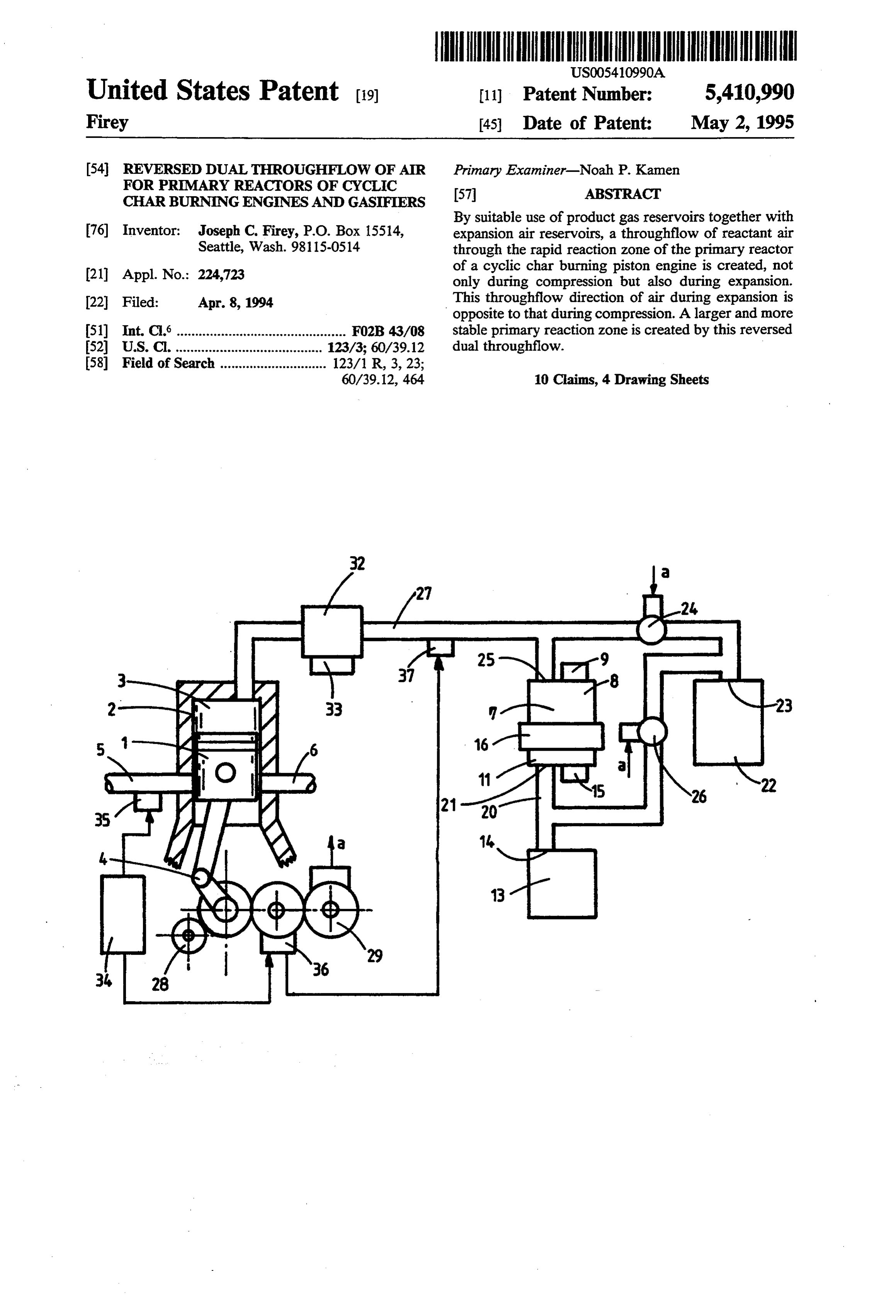
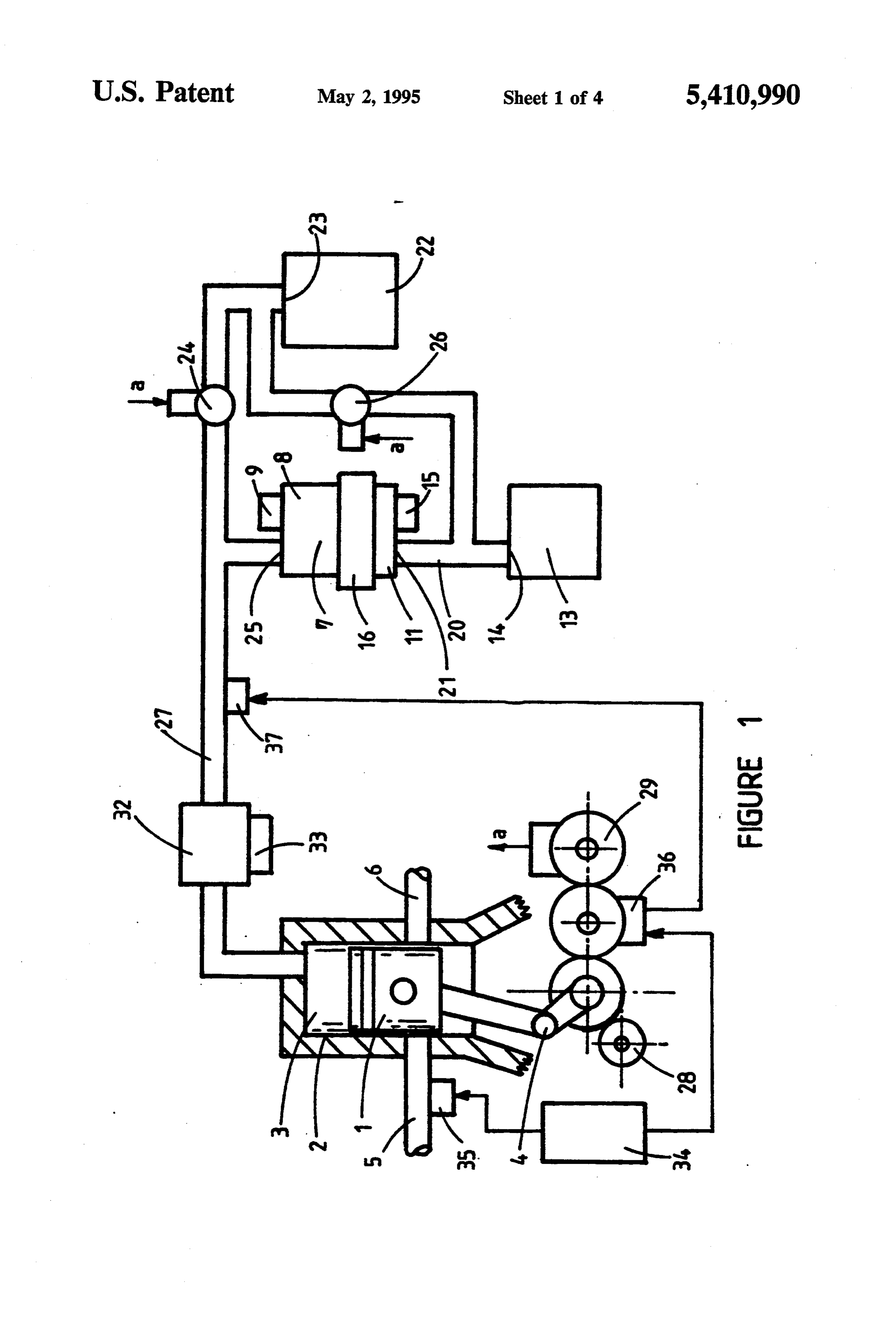
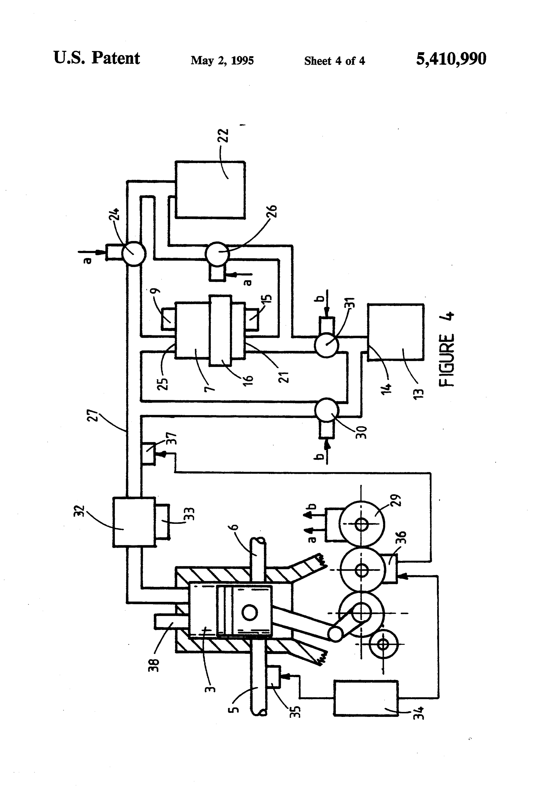
uses net work output can be done on the piston, since BRIEF DESCRIPTION OF THE FIGURES the various reactions of char fuel with oxygen and of product gases with oxygen are exothermic reactions FIG. 1 shows a first embodiment of the combination which are carried out under the varying pressures of the 45 of a char fuel gasifier and an engine. engine cycle. Herein and in the claims the term power FIG. 2 shows a detailed cross-section of the pressure reactor is used to mean either a cyclic char burning vessel and associated equipment.
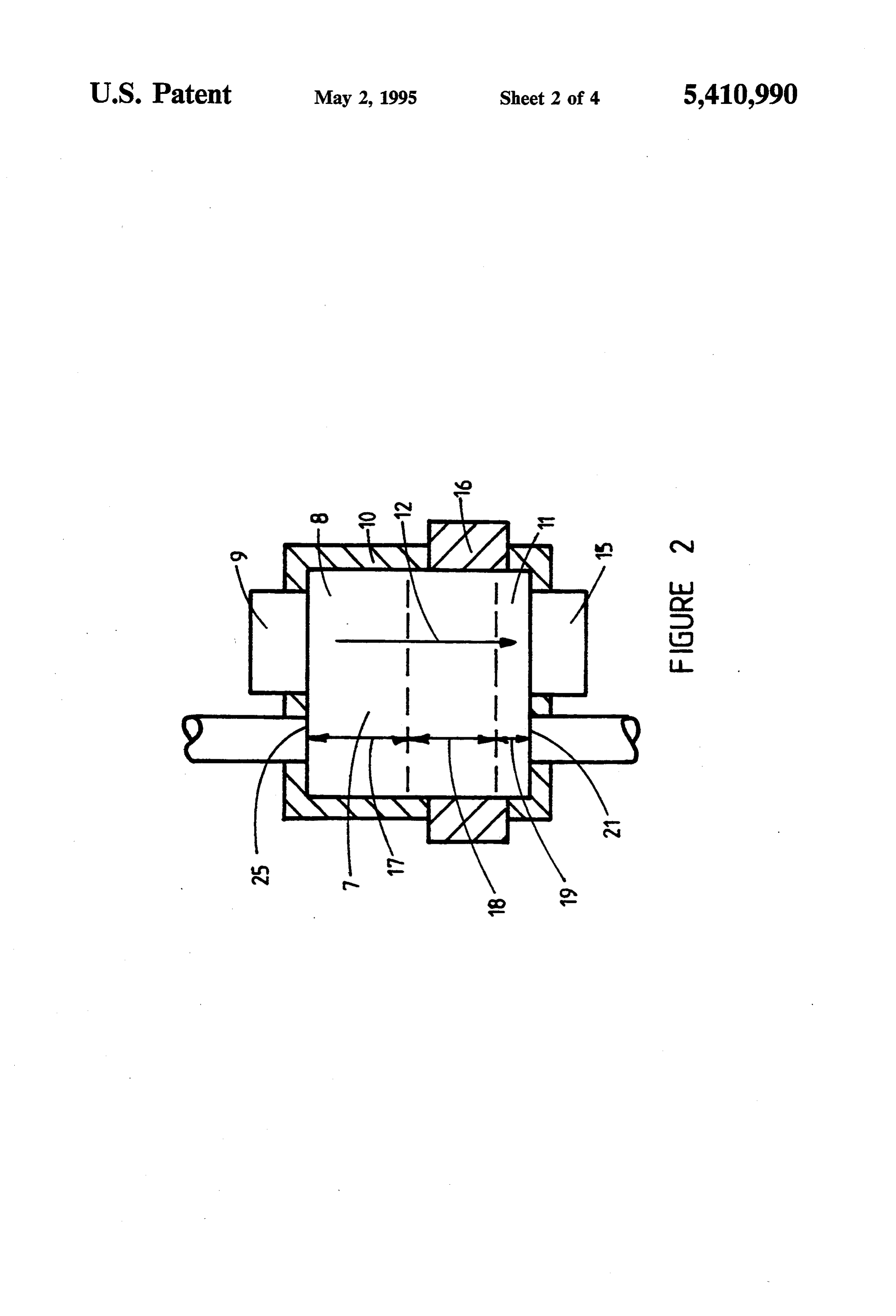
engine or a cyclic char burning gasifier. FIG. 3 shows a second embodiment of the device of The term fixed open gas flow connection is used FIG. 1.
herein and in the claims to mean a gas flow passage 50 FIG. 4 shows a third embodiment of the device of which remains open whenever the cyclic char burning FIG. I.
engine or gasifier is operating.
The term changeable gas flow connection is used DESCRIPTION OF THE PREFERRED herein and in the claims to mean a gas flow passage EMBODIMENTS which can be opened or closed while the cyclic char 55 All forms of this invention are improvements to cyc burning engine or gasifier is operating. A changeable lic char burning engines or gasifiers using a separated gas flow connection is opened and closed by a drive primary reaction chamber, an example of which is means for opening and closing and this is driven in turn shown schematically in FIG. 1 and 2, and comprises: from the internal combustion engine mechanism drive 1. A combined means for compressing and expanding means as is well known in the art of internal combustion 60 gases comprising: a piston, 1; operative within a engines. cylinder, 2; and these enclosing a variable volume As the char fuel, within the primary reactor, moves chamber, 3; whose volume varies cyclically as the along the char fuel motion direction it is preheated by piston is reciprocated by a drive means, 4. The heat transfer from char fuel portions which are further drive means, 4, reciprocates the piston, 1; thus along and are reacting rapidly with oxygen and thus are 65 varying the volume of the variable volume cham at a high temperature. Where the char fuel being used is ber, 3, creating a compression process for a com essentially free of volatile matter, as with coke fuel, this pression time interval when the piston, 1, is rising preheat zone serves to bring the new char fuel up to its and decreasing the volume of the variable volume
Page 8
chamber 3, creating an expansion process for an The devices of this invention comprise additions to expansion time interval when the piston, 1, is de the primary reaction chamber, 7, and the com scending and increasing the volume of the variable bined compressor and expander means, and gas volume chamber, 3. The combined means for con flow connecting means therebetween as follows: pressing and expanding shown in FIG. 1 further 5 5. A product gas reservoir, 13, is added, whose prod comprises: an intake means, 5, for placing air as uct gas reservoir gas flow opening, 14, is connected reactant gas into the variable volume chamber, 3, via a second fixed open gas flow connecting means, prior to each compression process when the piston, 20, to a gas flow opening, 21, at the ash collection 1, is at the bottom portion of its stroke; an exhaust end, 11, of the primary reaction chamber, 7, for this means, 6, for removing reacted gases from the 10 FIG. 1 and FIG. 2 form of the invention. variable volume chamber, 3, after each expansion 6. An expansion reactant gas reservoir, 22, is added, process when the piston, 1, is again at the bottom whose expansion gas reservoir gas flow opening, portion of its stroke. A two stroke cycle internal 23, is connected via a first changeable gas flow combustion engine mechanism is shown in FIG. 1 connecting means, 24, to a gas flow opening, 25, at but four stroke cycle internal combustion engine the refuel end, 8, of the primary reaction chamber, mechanisms can also be used. Also drive means 7. This first changeable gas flow connecting means other than the crank and connecting rod mecha- comprises a drive e3S for opening and closing nism of FIG. 1 can also be used such as the Wankel this connecting means while the cyclic char burn engine mechanism. 1ng power reactor 1s running. . A separated primary reaction chamber, 7, contains 20 7. The expansion reactant gas reservoir, 22, is addi char fuel which is added into the refuel end, 8, tionally connected via a second changeable gas thereof by a refuel mechanism, 9, and this primary flow connecting means, 26, to the gas flow open reactor comprises: a pressure vessel container, 10, ling, 21, at the ash collection end, 11, of the primary to contain the primary reaction chamber, 7; an ash reaction chamber, 7. This second changeable gas collection end, 11; a char fuel direction of motion, 25 few R"N, EP 2 Ey. leaS 12, from the refuel end, 8, toward the ash collection CEPE"3. us connecting t end, 11, in which direction the char fuel moves as Nin e cyclic c urnung power rea IybringI NA, 8. A first fixed open gas flow connecting means, 27, which in this Fig. 1 and 2 example removes ashes 30 s gas flow opening, i5, t l from the ash collection end, 11, of the primary As EP"Eg t case reactor, 7; a starting heater means, 16, for preheat- means for compressing and expanding ing the char fuel in the primary reactor, 7, up to 9. A control means, 29, is actuated, as via gears, by that temperature at which it reacts rapidly with as the internal combustion engine mechanism drive YE in adjacent E. reactant gas y
E2. cranked for starting, by the means, 4, and is operative upon the drive means of the changeablee gas flow connecting means, 24, 26, ank S, - . The fresh char fuel refueled into the refuel end, 8, Sisily Niger.
of the primary reactor, 7, is cold, and will not react 40 and changeable gas flow connecting means, 26, is with compressed air, but is heated by conduction closed; and during all expansion time intervals from those char fuel portions deeper into the pri changeable gas flow connecting means, 24, is mary reactor which are at a high temperature and closed and changeable gas flow connecting means, are reacting rapidly with oxygen to create pro- 26, is open. This control means can be mechanical, ducer gas. Thus the first portion, 17, of the primary 45 as with cams to operate the changeable gas flow reaction chamber along the char fuel motion direc connection drive means, or electrical, as with tion, 12, is a char fuel preheat zone, 17, and distilla switches to operate solenoid drive means in the tion of volatile matter takes place here also when changeable gas flow connections, or other types of char fuels containing volatile matter are being control devices.
used. At the end of the preheat zone, 17, the char 50 The particular example form of this invention shown fuel is at or above its rapid reaction temperature in FIGS. 1 and operates as follows:
and enters the rapid reaction zone portion, 18, of 10. When the cyclic charburning engine orgasifier of the primary reaction chamber along the char fuel FIG. 1 is to be started, the starting heater means, motion path, 12, where char fuel reacts rapidly 16, is energized, which heats up the char fuel in the with oxygen in adjacent compressed reactant 55 primary reactor, 7, to its rapid reaction tempera gases. The heat of this reaction maintains the rapid ture. The internal combustion engine mechanism reaction zone at or above the char fuel rapid reac drive means, 4, is then cranked by the cranking tion temperature. Within the rapid reaction zone, means, 28, for starting and cycles of compression 18, of the char fuel reactor, 7, the carbon of the followed by expansion are created within the vari char fuel is gasified to producer gas and leaves only able volume chamber, 3. Prior to each such com the ashes which collect in the ash zone, 19, at the pression air as reactant gas is placed inside the ash collection end, 11, of the char fuel motion path, variable volume chamber, 3, by the intake means, 5. 12. Following each such expansion reacted gas is re 4. Various means for connecting the primary reaction moved from the variable volume chamber, 3, by chamber, 7, to the variable volume chamber, 3, of 65 the exhaust means, 6.
the combined compressor and expander can be 11. During compression time intervals, reactant air used for this invention as will be described herein flows from the variable volume chamber, 3, into below. the primary reaction chamber, 7, via first fixed
Page 9
open gas flow connection, 27, and the refuel end 15. This flow reversal additionally assures that hot gas flow opening, 25. As pressure rises during com gases from the rapid reaction zone flow through pression some portions of this reactant air enter the the fresh char fuel in the char fuel preheat Zone, 17, interior pore spaces of the char fuel within the during expansion.
rapid reaction zone, 18, in the primary reactor and 5 This hot gas flow preheats the fresh char fuel more there reacts rapidly with the hot char fuel to form rapidly than is possible when preheat occurs only via a producer gas. Other portions of this reactant air solid state heat transfer through the char fuel chunks as enter the interior pore spaces of the char fuel is the case when gas flow is always unidirectional from within the char fuel preheat zone, 17, and are the refuel end toward the ash collection end of the stored therein during compression. Still other por 10 primary reaction chamber. Small volume primary reac tions of reactant air flow through the interstitial tion chambers are required for cyclic char burning spaces in the primary reactor and there react in power reactors of this invention in order to achieve part with outer surfaces of the hot char fuel. The adequate engine compression ratio and hence reason resulting product gases flowing through these in able engine efficiency. There is thus only a small reactor terstitial spaces then flow on into the product gas 5 cross sectional area available for solid state heat transfer reservoir, 13, via the second fixed open gas flow through the char fuel chunks. Thus char fuel preheat by connection, 20, and the product gas reservoir gas flow of hot gases through the fresh char fuel is pre flow opening, 14, and are stored therein during ferred for primary reactors of cyclic char burning compression. Reactant air flows also from the vari power reactors.
able volume chamber, 3, into the expansion reac 20 16. Mixtures of carbon monoxide, a principal fuel tant gas reservoir, 22, via the open first changeable component of the product producer gas, with sec gasflow connection, 24, and the expansion reactant ondary air for the complete combustion reaction in gas reservoir gas flow opening, 23, during com the variable volume chamber are difficult to ignite pression, the second changeable gas flow connec in the absence of hydrogen or steam. The steam or tion, 26, being then closed. Reactant air is thus 25 hydrogen needed for producer gas ignition may be stored within the expansion reactant gas reservoir present in the char fuel being used or, if not, can be during compression. supplied separately as described hereinbelow. 12. During expansion time intervals, as the pressure 17. Any one of several different types of starting decreases, producer gas emerges from the interior heater means, 16, can be used such as electric heat pore spaces of the rapid reaction zone, 18, and 30 ers, or oil fired heaters, or fuel gas fired heaters. reactant air emerges from the interior pore spaces Examples of some starting heater means are de of the char fuel preheat zone, 17. Stored product scribed in the material incorporated by reference in gases flow out of the product gas reservoir, 13, and the description of the prior art. flow through the interstitial spaces in the primary 18. Oxygen and steam in the air, forced by compres reactor, 7. Stored expansion reactant air flows out 35 sion into the interior pore spaces of the hot char of the expansion reactant gas reservoir, 22, and into fuel within the rapid reaction zone, reacts quickly the primary reactor, 7, via the now open second with the adjacent carbon of the char fuel. This changeable gas flow connection, 26, and the ash reaction of steam and oxygen with char fuel, within collection end gas flow opening, 21, the first the interior pore spaces, is more rapid and more changeable gas flow connection, 24, being closed complete than the corresponding reactions within during expansion. This stored expansion reactant the interstitial spaces due to a closer contact of air also flows through the interstitial spaces in the steam and oxygen to the char fuel within the pore primary reactor, 7, and there reacts with hot char spaces. The reaction within the interior pore spaces fuel to form additional producer gas. is also more complete than in the interstitial spaces 13. Thus, during expansion time intervals these vari 45 since the pore reactant gases remain inside the pore ous gases are flowing through the interstitial spaces spaces throughout the compression time interval in the primary reactor, 7, and on into the expanding whereas the interstitial reactant gases pass through variable volume chamber, 3, via the refuel end gas the rapid reaction zone and are present therein flow opening, 25, and the first fixed gas flow con during only a portion of the compression time in nection, 27. 50 terval. Thus by increasing the volume of the rapid 14. During compression time intervals gases flow reaction zone, and hence increasing the proportion through the primary reaction chamber, 7, in a di of reaction occurring inside the pore spaces, the rection from the refuel end, 8, toward the ash col devices of this invention increase the net rate of lection end, 11. During expansion time intervals the char fuel reaction per cycle and thus make possible gas flow direction is reversed from that during 55 the use of higher engine speeds and this is another compression and is from the ash collection end beneficial object of this invention. toward the refuel end. This flow reversal acts to A modified form of the invention is shown schemati increase the volume of the high temperature reac cally in FIG. 3 wherein the connections into and out of tion zone and thus to increase the reaction zone the primary reaction chamber are opposite ended from stability and this is one of the beneficial objects of 60 those shown in the FIG. 1 form of the invention. Thus this invention. The rapid reaction zone tends to in FIG. 3: the first fixed open gas flow connecting migrate slowly toward the source of oxygen since means, 27, from the variable volume chamber, 3, con reaction speed is higher at higher oxygen gas con nects to the ash collection end gas flow opening, 21, of centrations. By supplying reactant gas containing the primary reaction chamber, 7; the second fixed open appreciable oxygen gas, first in one direction, and 65 gas flow connecting means, 20, to the product gas reser then in the opposite direction, the rapid reaction voir, 13, connects to the refuel end gas flow opening, zone expands in both directions and thus increases 25, of the primary reaction chamber, 7; the first change in volume. able gas flow connecting means, 24, from the expansion
Page 10
reactant gas reservoir, 22, connects to the ash collection these particles into the combined means for compress end gas flow opening, 21, of the primary reaction cham ing and expanding. Various types of separator means ber, 7; and the second changeable gas flow connecting can be used such as cyclone separators or other centrif means, 26, from the expansion reactant gas reservoir, ugal force separators. An ash removal means, 33, can be 22, connects to the refuel end gas flow opening, 25, of 5 added to the particle separator means, 32, to remove the the primary reaction chamber, 7. Thus the FIG. 3-form collected particles.
of the invention differs from the FIG. 1 form of the When using char fuels of zero or very low hydrogen invention only in that during compression time intervals content steam additions to the reactant gases may be gas flow direction in the primary reaction chamber, 7, is needed to obtain sufficiently rapid ignition and burning from the ash collection end, 11, toward the refuel end, O of carbon monoxide with oxygen in the secondary reac 8, and is the opposite direction during expansion time tion as described hereinabove.
intervals. Whichever connection pattern is used, the Steam may be thusly added by introducing steam first changeable gas flow connecting means, 24, from from a steam source, 34, into the intake means, 5, of the the expansion reactant gas reservoir, 22, always con combined means for compressing and expanding, 1, via nects to that gas flow opening of the primary reactor, 7, 15 a steam inlet, 35. Alternatively steam can be introduced to which the first fixed open gas flow connection, 27, into the reactant gases containing oxygen gas as these from the variable volume chamber is also connected, are flowing into the primary reactor, 7, and the expan and is open only during all compression time intervals. sion reactant gas reservoir, 22. Steam from the steam Similarly the second changeable gas flow connecting source, 34, can be added to reactant gases flowing means, 26, from the expansion reactant gas reservoir, 20 through the first fixed open gas flow connection, 27, via 22, always connects to that other gas flow opening of steam admission means, 36, and a steam inlet, 37. The the primary reactor, 7, to which the first fixed open gas steam admission means, 36, can be driven from the inter flow connection, 27, from the variable volume chamber nal combustion engine mechanism in order to time is not connected, and is open only during all expansion steam admission to occur only during all compression time intervals. 25 time intervals. The added steam can function not only In some char burning engines it may be preferable to as a carbon monoxide ignition agent for the secondary pass the product gases directly into the variable volume reaction but also as a carbon gasifying agent. chamber so that these product gases bypass the primary Having thus described my invention what I claim is: reactor during expansion. In this way the reactant air, 1. In a cyclic char burning power reactor comprising: flowing through the primary reactor, from the expan 30 at least one combined means for compressing and ex sion reactant gas reservoir, during expansion is not di panding gases, each said combined means comprising; luted by these product gases from the product gas reser an internal combustion engine mechanism comprising a voir. An example of this bypass form of the invention is variable volume chamber for compressing and expand shown schematically in FIG. 4 whose several elements ing gases, and drive means for driving said internal are similar and function similarly to those described 35 combustion engine mechanism and for varying the hereinabove for the FIG. 1 and FIG. 2 form of the volume of said chamber through repeated cycles, each invention except as follows. A third changeable gas cycle comprising a compression time interval followed flow connecting means, 30, connects the product gas by an expansion time interval, each said combined reservoir, 13, gas flow opening, 14, to that one gas flow means for compressing and expanding further compris opening, 25, of the primary reaction chamber, 7, to ing, intake means for admitting reactant gases into said which the first fixed open gas flow connection, 27, from variable volume chamber prior to each said compres the variable volume chamber, 3, is also connected. A sion time interval, exhaust means for removing reacted fourth changeable gas flow connecting means, 31, con gases from said variable volume chamber after each said nects the product gas reservoir, 13, gas flow opening, expansion time interval; each said combined means for 14, to that other gas flow opening, 21, of the primary 45 compressing and expanding being connected to a sepa reactor, 7, to which the first fixed open gas flow con rate primary reaction chamber, within a pressure vessel nection, 27, from the variable volume chamber, 3, is not container, each said primary reaction chamber compris connected. The third changeable gas flow connection, ing; a refuel end with a refuel mechanism means for 30, is open only during all expansion time intervals and supplying fresh char fuel particles into said refuel end, the fourth changeable gas flow connection, 31, is open 50 an ash collection end, a char fuel direction of motion only during all compression time intervals as addition from said refuel end toward said ash removal end, each ally controlled by the control means, 29. In this way said primary reaction chamber further comprising, a product gases flow into the product gas reservoir, 13, char fuel preheat zone positioned toward said refuel end from the primary reactor, 7, during compression, and of said primary reaction chamber, an ash collection flow into the variable volume chamber, 3, directly from 55 zone positioned toward said ash collection end of said the product gas reservoir, 13, and thus bypass the pri primary reaction chamber, and a rapid reaction zone mary reactor, 7, during expansion. positioned between said char fuel preheat zone and said For those cyclic char burning power reactors which ash collection zone, each said primary reaction chamber are to operate as engines using complete combustion of further comprising at least one means for removing the product producer gas with added secondary air in 60 ashes; said char burning power reactor being connected the variable volume chamber, 3, an igniter means for to a source of supply of reactant gas containing appre igniting mixtures of fuel gas in secondary air, 38, may be ciable oxygen gas for each said intake means for admit used. Any of various types of igniter means may be used ting reactant gases into said variable volume chamber; for this purpose. said char burning power reactor further comprising: A particle separator means for separating solid and 65 means for preheating said char fuel within said primary liquid particles, 32, can be installed between the variable reaction chamber to that temperature at which said char volume chamber, 3, and the first fixed open gas flow fuel reacts rapidly with oxygen in adjacent compressed connecting means, 27, in order to prevent carryover of reactant gases when said char burning power reactor is
Page 11
being started; means for cranking said internal combus 4. In a cyclic char burning power reactor as described tion engine mechanism when said char burning power in claim 1 and further comprising:
reactor is being started: separator means for separating solid and liquid parti an improvement comprising adding to each said pri cles from gases flowing therethrough; said separa mary reaction chamber: tor means being placed between said variable vol a product gas reservoir comprising a product gas ume chamber of said internal combustion engine reservoir gas flow opening; mechanism and said first fixed open gas flow con an expansion reactant gas reservoir comprising an necting means to said primary reaction chamber; expansion reactant gas reservoir gas flow opening; said separator means comprising ash removal Said primary reaction chamber comprising two sepa 10 means for removing separated and collected solid rate gas flow openings, a refuel end gas flow open and liquid particles from said separator means. ing and an ash collection end gas flow opening;
a first fixed open gas flow Connecting means for in 5.claim In a cyclic char burning power reactor as described 1 and further comprising:
connecting between said variable volume chamber a source of steam;
of said internal combustion engine mechanism and 15 steam admission means for adding steam from said one of said two separate gas flow openings of said steam source into said reactant gas containing ap primary reaction chamber; preciable oxygen gas flowing through said first a first changeable gas flow connecting means for fixed open gas flow connecting means between said connecting between said expansion reactant gas variable volume chamber and one of said two sepa reservoir gas flow opening and that one of said two 20 rate gas flow openings of said primary reaction separate gas flow openings of said primary reaction chamber, during all compression time intervals, so chamber to which said first fixed open gas flow that steam is added into reactant gases flowing into connecting means from said variable volume cham said primary reaction chamber and into said expan ber is connected, said first changeable gas flow connecting means comprising first drive means for 25 6. sionIn a reactant gas reservoir.
cyclic char burning power reactor comprising:
opening and closing said first changeable gas flow connecting means while said cyclic char burning at least one combined means for compressing and ex panding gases, each said combined means comprising:
power reactor is running;
a second changeable gas flow connecting means for an internal combustion engine mechanism comprising a connecting between said expansion reactant gas 30 variable volume chamber for compressing and expand reservoir gas flow opening and that other one of ing gases, and drive means for driving said internal said two separate gas flow openings of said primary combustion engine mechanism and for varying the vol reaction chamber to which said first fixed open gas ume of said chamber through repeated cycles, each flow connecting means from said variable volume cycle comprising a compression time interval followed chamber is not connected, said second changeable 35 by an expansion time interval, each said combined gas flow connecting means comprising second means for compressing and expanding further compris drive means for opening and closing said second ing, intake means for admitting reactant gases into said changeable gas flow connecting means while said variable volume chamber prior to each said compres cyclic char burning power reactor is running; sion time interval, exhaust means for removing reacted a second fixed open gas flow connecting means be gases from said variable volume chamber after each said tween said product gas reservoir gas flow opening expansion time interval; each said combined means for and that other one of said two separate gas flow compressing and expanding being connected to a sepa openings of said primary reaction chamber to rate primary reaction chamber, within a pressure vessel which said first fixed open gas flow connecting container, each said primary reaction chamber compris means is not connected; 45 ing; a refuel end with a refuel mechanism means for control means for controlling the opening and closing supplying fresh char fuel particles into said refuel end, of said changeable gas flow connections, operative an ash collection end, a char fuel direction of motion upon said means for opening and closing said from said refuel end toward said ash removal end, each changeable gas flow connections, and actuated by said primary reaction chamber further comprising, a said internal combustion engine mechanism of said 50 char fuel preheat zone positioned toward said refuel end cyclic char burning power reactor; so that during of said primary reaction chamber, an ash collection all compression time intervals; said first changeable zone positioned toward said ash collection end of said gas flow connecting means is open and said second primary reaction chamber, and a rapid reaction zone changeable gas flow connecting means is closed; positioned between said char fuel preheat zone and said and so that during all expansion time intervals; said 55 ash collection zone, each said primary reaction chamber first changeable gas flow connecting means is further comprising at least one means for removing closed and said second changeable gas flow con ashes; said char burning power reactor being connected necting means is open. to a source of supply of reactant gas containing appre 2. In a cyclic charburning power reactor as described ciable oxygen gas for each said intake means for admit in claim 1: ting reactant Bases into said variable volume chamber; wherein said first fixed open gas flow connecting said char burning power reactor further comprising: means is connected to said refuel end gas flow means for preheating said char fuel within said primary opening of said primary reaction chamber. reaction chamber to that temperature at which said char 3. In a cyclic char burning power reactor as described fuel reacts rapidly with oxygen in adjacent compressed in claim 1: 65 reactant gases when said char burning power reactor is wherein said first fixed open gas flow connecting being started; means for cranking said internal combus means is connected to said ash collection end gas tion engine mechanism when said char burning power flow opening of said primary reaction chamber. reactor is being started:
Page 12
an improvement comprising adding to each said pri means for opening and closing said fourth change mary reaction chamber: able gas flow connecting means while said cyclic a product gas reservoir comprising a product gas char burning power reactor is running; reservoir gas flow opening; control means for controlling the opening and closing an expansion reactant gas reservoir comprising an 5 of said changeable gas flow connections, operative expansion reactant gas reservoir gas flow opening; upon said means for opening and closing said said primary reaction chamber comprising two sepa changeable gas flow connections, and actuated by rate gas flow openings, a refuel end gas flow open said internal combustion engine mechanism of said ing and an ash collection end gas flow opening; cyclic char burning power reactor; so that during a first fixed open gas flow connecting means for con 10 all compression time intervals; said first changeable necting between said variable volume chamber of gas flow connecting means and said fourth change said internal combustion engine mechanism and able gas flow connecting means are open, and said one of said two separate gas flow openings of said second changeable gas flow connecting means and primary reaction chamber; said third changeable gas flow connecting means A first changeable gas flow connection means for 15 are closed; and so that during all expansion time connecting between said expansion reactant gas intervals; said first changeable gas flow connecting reservoir gas flow opening and that one of said two means and said fourth changeable gas flow con separate gas flow openings of said primary reaction necting means are closed, and said second change chamber to which said first fixed open gas flow able gas flow connecting means and said third connecting means from said variable volume cham 20 changeable gas flow connecting means are open. ber is connected, said first changeable gas flow 7. In a cyclic charburning power reactor as described connecting means comprising first drive means for in claim 6:
opening and closing said first changeable gas flow wherein said first fixed open gas flow connecting connecting means while said cyclic char burning means is connected to said refuel end gas flow power reactor is running; 25 opening of said primary reaction chamber. a second changeable gas flow connecting means for 8. In a cyclic charburning power reactor as described connecting between said expansion reactant gas in claim 6:
reservoir gas flow opening and that other one of wherein said first fixed open gas flow connecting said two separate gas flow openings of said primary means is connected to said ash collection end gas reaction chamber to which said first fixed open gas 30 flow opening of said primary reaction chamber. flow connecting means from said variable volume 9. In a cyclic charburning power reactor as described chamber is not connected, said second changeable in claim 6 and further comprising:
gas flow connecting means comprising second separator means for separating solid and liquid parti drive means for opening and closing said second cles from gases flowing therethrough; said separa changeable gas flow connecting means while said 35 tor means being placed between said variable vol cyclic char burning power reactor is running; ume chamber of said internal combustion engine a third changeable gas flow connecting means for mechanism and said first fixed open gas flow con connecting between said product gas reservoir gas necting means to said primary reaction chamber; flow opening and that one of said two separate gas said separator means comprising ash removal flow openings of said primary reaction chamber to means for removing separated and collected solid which said first fixed open gas flow connecting and liquid particles from said separator means. means from said variable volume chamber is con 10. In a cyclic char burning power reactor as de nected, said third changeable gas flow connecting scribed in claim 6 and further comprising: means comprising third drive means for opening a source of steam;
and closing said third changeable gas flow connect 45 steam admission means for adding steam from said ing means while said cyclic char burning power steam source into said reactant gas containing ap reactor is running; preciable oxygen gas flowing through said first a fourth changeable gas flow connecting means for fixed open gas flow connecting means between said connecting between said product gas reservoir gas variable volume chamber and one of said wo sepa flow opening and that other one of said two sepa 50 rate gas flow openings of said primary reaction rate gas flow openings of said primary reaction chamber, during all compression time intervals, so chamber to which said first fixed open gas flow that steam is added into reactant gases flowing into connecting means from said variable volume cham said primary reaction chamber and into said expan ber is not connected, said fourth changeable gas sion reactant gas reservoir. flow connecting means comprising fourth drive 55 t k k e
Provenance
- Collection
- Cited prior art
- Original PDF
- patentimages.storage.googleapis.com →
- Filed
- 1994-04-08
- Pages
- 12
- Method
- pdftotext (the PDF's own text layer) + pdftoppm 300dpi page scans
- Source
- Google Patents bibliographic record
- Granted
- 1995-05-02
- Inventors
- Joseph C. Firey
- Transcribed from
- patentimages.storage.googleapis.com →