patent · US4147142
Fuel modification system for internal combustion engines
3 April 1979
Page 1 — bibliographic record
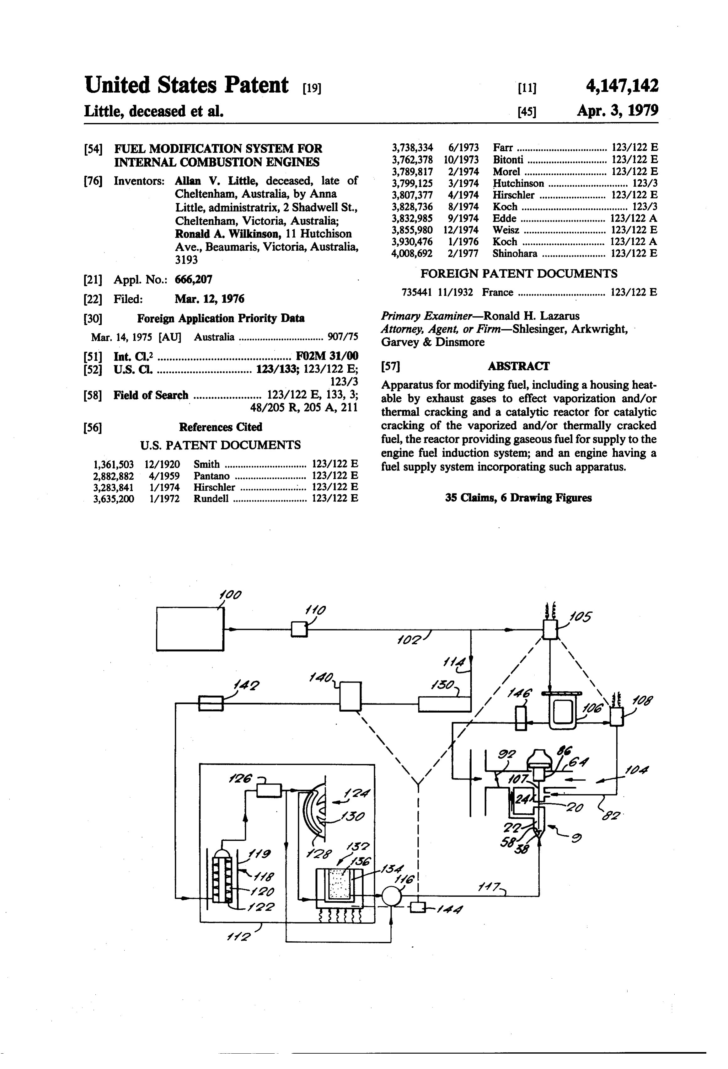
United States Patent (19) 11 4,147,142 Little, deceased et al. 45) Apr. 3, 1979 (54) FUEL MODIFICATION SYSTEM FOR 3,738,334 6/1973 Farr.................................. 123/122 E. INTERNAL COMBUSTON ENGINES 3,762,378 10/1973 Bitonti.............................. 123/122 E 3,789,817 2/1974 Morel ............................... 123/122 E.
76 Inventors: Allan W. Little, deceased, late of 3,799,125 3/1974 Hutchinson .............................. 123/3 Cheltenham, Australia, by Anna 3,807,377 4/1974 Hirschler ......................... 123/122 E Little, administratrix, 2 Shadwell St., 3,828,736 8/1974 Koch ........................................ 123/3 Cheltenham, Victoria, Australia; 3,832,985 9/1974 Edde................................ 123/122 A Ronald A. Wilkinson, 11 Hutchison 3,855,980 12/1974 Weisz ............................... 123/122 E. Ave., Beaumaris, Victoria, Australia, 3,930,476 1/1976 Koch .......... ... 123/122 A 31.93 4,008,692 2/1977 Shinohara ........................ 123/122 E
FOREIGN PATENT DOCUMENTS
735441 11/1932 France ................................. 123/122 E
30 Foreign Application Priority Data Primary Examiner-Ronald H. Lazarus Attorney, Agent, or Firm-Shlesinger, Arkwright,
Mar, 14, 1975 AU Australia ................................ 907/75 Garvey & Dinsmore 51) Int. C.’............................................. FO2M 31/00 57 ABSTRACT 52 U.S. C. ................................ 123/133; 123/122 E;
123/3 Apparatus for modifying fuel, including a housing heat 58 Field of Search ....................... 123/122 E, 133,3; able by exhaust gases to effect vaporization and/or 48/205 R, 205 A, 211 thermal cracking and a catalytic reactor for catalytic 56) References Cited cracking of the vaporized and/or thermally cracked
engine fuel induction system; and an engine having a 1,361,503 12/1920 Smith ............................... 123/122 E fuel supply system incorporating such apparatus. 2,882,882 4/1959 Pantano ... ... 123/122 E.
3,283,841 1/1974 Hirschler ..... ... 123A122 E 3,635,200 1/1972 Rundell ............................ 123/122 E 35 Claims, 6 Drawing Figures
Page 2
Drawing sheet — no readable text.
Page 3
Drawing sheet — no readable text.
Page 4
Drawing sheet — no readable text.
Page 5
Drawing sheet — no readable text.
Page 6
Drawing sheet — no readable text.
Page 7
Drawing sheet — no readable text.
Page 8
required to be completed in the combustion chamber.
FUEL MODIFICATION SYSTEM FOR INTERNAL This applies particularly to the higher boiling point COMBUSTON ENGINES : fractions of the fuel. Fuel injection systems rely for vapourization upon heat relation to the more finely
This invention relates to a system for modifying fuel 5 dispersed fuel droplets.
for internal combustion engines such as for automotive For the exothermic reaction of carbonaceous fuels or marine use and, in particular, for modifying petrol by with oxygen, they must be in a gaseous or vapour state. vapourization and/or cracking. However, the rate and mechanistic pathway by which Increasing concern about the role played by the auto the fuel is burned depends, inter alia, upon whether all mobile as a major contributor to aerial pollution has led 10 of the fuel/air mixture is physically homogeneous or to intensified research into means of controlling the heterogenous of state.
composition of exhaust gases of the petrol (gasoline) If the mixture is physically homogenous, burning engine. Lack of control over the chemical reactions takes place by a reasonably uncomplicated hydroxyl occurring during combustion is the direct result of an ation free radical mechanism to the end products carbon expedient approach on the part of the manufacturer, for 15 dioxide (CO2) and water (H2O). If liquid and/or solid it has long been known that the requirements for rapid particles are present and if the speed of flame propaga increases in power output during normal driving are tion is high some heat energy is used in thermal crack assisted by an increase in the fuel/air ratio. ing of the fuel. During this thermal cracking smaller The fuel/air ratio (mixture strength) is, at any time, molecular fragments, including radicals, may primarily dependent upon the design of the fuel meter 20 (a) react with O2 is a more complex way than that of ing equipment. Control of the chemical reactions, how the hydroxylation mechanism referred to above. Unsta ever, is dependent mainly upon physical and physico ble peroxides can form which in turn decompose uncon chemical factors rather than mathematical ones. Pres trollably to produce a variety of organic end products, ent-day metering devices used on mass-produced auto e.g. ethers, acids and esters;
mobiles cannot provide the correct condition for effi 25 (b) polymerize to higher molecular weight product cient combustion of present-day liquid fuel mixtures. s-e.g. large hydrocarbon molecules; Liquid fuel carburettors presently in use fall into two (c) react with other radical intermediates again pro main classes: namely, ducing various organic end products; and i. atmospheric pressure spray system-the two-fluid (d) dehydrogenate with formation of element carbon. spray, which can be further subdivided into static 30 Wherever thermal cracking of high boiling point fuel and dynamic types; and occurs in the combustion chamber of spark ignition ii. above atmospheric pressure spray system-single engines, there is usually insufficient oxygen available in fluid spray, known as fuel injection. the regions of high hydrocarbon concentration for com By far the most serious disadvantage suffered by all pletion of combustion within the time available. spray carburettors is their inability to cope with the 35 Clean, complete combustion is therefore not possible large differences in both density and viscosity which at high speeds in engines using spray system carbure exist between the metered fluids viz. air and fuel. Carbu tion.
rettors are volume proportioning devices. Thus very It follows from the above discussion that almost all of small volumes of (high density) fuel are required for the deficiencies of spray systems are absent in the gas large volumes of (low density) air, particularly since carburettor/manifold system of fuel feed. However, gas nitrogen, which accounts for almost 80% of the air engines suffer the obvious practical disadvantages of inspired, contributes nothing to the exothermic reac fuel storage space at low pressure or heavy tank and tions of combustion. For a stoichiometric reaction mix space requirements at high pressure. ture, only about 2% of total inspired volume is fuel It is desirable to modify the chemical composition of when calculated on a volume basis with the fuel in a 45 the petroleum fuel as well as providing the required vapour state. Thus the metering of small volumes of physical state for combustion. The requirement by reg liquid fuel require small metering orifices which must be ulation for vehicle manufacturers to meet pollution carefully designed around the viscosity characteristics standards through the use of lead-free fuels imposes an of fluid flow. octane rating limitation on fuels or an increased refining Static type carburettors using submerged jets require 50 cost to maintain the rating through the use of increased air correction at high gas velocities through the choke quantities of reformed hydrocarbons. tube. Dynamic carburettors using an annular metering It has been found that these limitations and costs can, orifice, which is also the discharge orifice, exhibit com however, be avoided by up-grading the preferably lead plex discharge characteristics. These require correction 55 free fuel by the use of waste exhaust heat. This is in the form of a complex metering needle profile. achieved by thermal vapourization and/or cracking Two-fluid spray type carburettors also suffer before metering to the air stream. During the cracking (a) settling out of fuel spray in the intake manifold, short chain hydrocarbons, including methane (CH4), which often is aggravated by impingement upon the may be produced.
throttle plate; and In addition any elemental hydrogen formed can serve (b) variable vacuum flash-off in the intake manifold as 60 three main functions:
a function of engine load. 1. It provides an important additional source of hy At small throttle openings, flash-off is maximal and droxyl radicals for the propagative combustion reac gas velocity minimal. At wide throttle openings, virtu tions of carbon fuels to carbon dioxide. In particular ally no vacuum flash-off occurs, and vapourization of carbon monoxide can only oxidize at a significant rate the fuel can only take place via heat radiation and con 65 to carbon dioxide via the hydroxyl radical reaction, duction to both the entrained spray and settled-out fuel.
But since velocities in the manifold are high, little time is available for vapourization which must finally be
Page 9
and H. --O2-).OH-O, is the oxygen-consuming reac extending longitudinally of the duct portion, the outlet tion. The efficiency of conversion of CO to CO2 is not conduit being adapted for connection to the fuel induc primarily dependent upon oxygen supply but upon the tion system of the engine, the arrangement being such ability of the combustion mixture to provide a source of that flow of fuel between the inlet and outlet is counter hydroxyl radicals from water or hydrogen, water being 5 directional to exhaust gas flow through the duct por formed as an end product of the proceeding hydrocar tion.
bon oxidation. The hydroxyl radicals derived from The housing of the apparatus may be defined by an water must arise via an endothermic back reaction in outer encircling wall and an inner wall defining a bore the presence of a catalyst (i.e. a radical M*): extending through the housing, the inner and outer 10 walls defining the chamber therebetween, whereby hot exhaust gases may flow through and around the cham or alternatively depend upon the prior production of O. ber. Such housing may be of annular form, the means or H. radicals: therein defining a tortuous or labyrinth path being in the
form of a helical baffle, with the inlet and outlet each being adjacent a respective end of the baffle.
The baffle or baffles of the chamber of the first stage and may be shaped and/or positioned so as to impart a O.--H2O22.OH whirling motion to fuel fed thereto. Such motion may 20 be such as to give rise to centrifugal forces which en
The addition of hydrogen to the fuel on the other hand hance contact and hence heat exchange between the provides a net exothermic production of .OH radicals to fuel and surfaces of the chamber, to effect vaporization improve the efficiency of carbon dioxide formation. and/or thermal cracking of fuel passed through the 2. The wide flammability limits and higher flame chamber.
speed of hydrogen are important in assisting the ignition In a second aspect, the present invention provides and flame propagation of lean mixtures-which are de 25 apparatus for use in modifying fuel for an internal com fined as those air/fuel ratios in excess of the stoichio bustion engine fuel system, comprising a housing defin metric value-and, in accordance with the known fact, ing a chamber having an inlet and an outlet for passage nitrogen oxide (NO) formation will decrease with in of fluid hydrocarbon fuel therethrough, the housing creasing degree of lean-ness provided a progressive being adapted for direct, external flame heating,
whereby fuel received at the inlet is vaporized and/or 3. Some elemental hydrogen is capable of being selec thermally tively diffused to catalytic exhaust reactors for the pur cracked during flow to the outlet. pose of reducing any oxides of nitrogen (NO) that are The chamber may be adapted for direct flame heating produced during combustion back to elemental nitro thereof for heating fuel passed therethrough, such as by gen. 35 positioning the chamber within an outlet manifold for The present invention is concerned with providing an the engine; the housing defining an elongate chamber improved fuel modifier suited for modification of the extending within the manifold at least once across inlet physical state and/or the chemical composition of a fuel ports thereof, the outlet of the chamber being in com such as petrol. The invention also is concerned, but not munication with a conduit extending through a defining exclusively, with an improved fuel modifier suited to wall of the manifold and adapted for connection to the provide fuel for use in a gas/gas carburettor system and, fuel induction system of the engine. in particular, such a carburettor system having a bi Such stage, hereinafter referred to as the second functional fuel metering system such as disclosed in our stage, may be used for vaporization and/or thermal copending application, Ser. No. 666,448, filed Mar. 12, cracking of fuel passed therethrough. 1976. 45 In a third aspect, the invention provides apparatus, The fuel modifier may comprise a liquid fuel vapouri hereinafter referred to as a third stage, for use in modi zation and/or fuel cracking stage or stages. fying fuel for an internal combustion engine fuel system, In one aspect, the present invention provides appara comprising means defining a housing for a cracking tus for use in modifying fuel for an internal combustion catalyst for hydrocarbon fuel, the housing having an engine fuel system, comprising a housing defining a 50 inlet by which fuel is receivable and an outlet connect chamber having an inlet and an outlet for passage of able to the fuel induction system of the engine. fluid hydrocarbon fuel therethrough, the chamber hav Such third stage may be of a form having provision ing therein means defining a tortuous or labyrinth path for passing fluid between walls defining the chamber for for the fuel in flow from the inlet to the outlet, the modifying the temperature of catalyst and fuel in the housing being adapted for external heating whereby 55 chamber. Thus, the housing defining means may include fuel received at the inlet as a liquid is vaporized and/or a heavy walled metal enclosure for the catalyst thermally cracked during flow to the outlet. mounted on an exhaust manifold for the engine, the The housing may be adapted to be mounted in an walls of the enclosure having a duct therein in commu exhaust system for the engine whereby heating of the nication with the interior of the manifold, there being housing is effectable by contact with exhaust gases of 60 valve means for controlling flow of exhaust gas from the engine. For this purpose, the housing may be the manifold through the duct and operable on attain mounted within a portion of an exhaust duct, such that ment of a predetermined housing temperature to close the inlet and outlet are spaced longitudinally of that the duct against such flow. The valve means may have duct portion, the inlet being in communication with the associated therewith temperature responsive means for exterior of the duct portion through a conduit extending 65 opening and closing the duct. laterally through a wall defining the duct portion and The apparatus of the first, second and/or third as adapted for connection to a source of fuel for the en pects may be used in combination, with the output of gine. The inlet may be in communication with a conduit the chamber of the first being in communication with
Page 10
the inlet to the second or third or the output of the the induction system. The by-pass circuit and the modi second chamber being in communication with the third. associatedsystem fied-fuel each may have a control valve, the means being a thermo-switch adapted to
In one form, all three aspects are used in conjunction, the invention in a fourth aspect therefore providing close and open the valve of the by-pass circuit and open and close the valve of the modified-fuel system in de apparatus for use in modifying fuel for an internal com 5 pendence bustion engine fuel system, comprising first and second the predetermined of the engine temperature being at or below housings defining respective first and second chambers temperature. each having an inlet and an outlet, with the outlet of the The by-pass circuit. may further include a float con first chamber being in communication with the inlet of 10 trolled fuel bowl for receiving fuel from the source via the second chamber, the first chamber having therein the control valve of the circuit, and for supplying fuel to means defining a tortuous or labyrinth path for fuel in a jet bridge of the induction system via a second control flow from the inlet to the outlet thereof, the first cham valve of the circuit, the second control valve openable ber being adapted for external heating whereby fuel and closable with opening and closing of the first-men received at the inlet as a liquid is vaporized and/or tioned control valve of the circuit. thermally cracked during flow to the outlet, and means 15 In the foregoing apparatus and engine based thereon, defining a housing for a cracking catalyst for hydrocar there may be an accumulation chamber for storing gase bon fuel having an inlet, in communication with the ous ent hydrocarbon fuel that is non-condensable at ambi temperature, the accumulation chamber having an chamber outlet for receiving fuel therefrom, and an outlet connectable to the fuel induction system of the 20 inlet in communication with a conduit providing com engine for the supply of fuel after passage through the munication between the outlet of the second chamber catalyst, the second housing being adapted for direct, and the inlet of the third housing and/or a conduit for external flame heating, whereby fuel received at the providing communication between the outlet of the third housing and the fuel induction system of the en inlet is vaporized and/or thermally cracked during flow gine, and an outlet for providing communication be to the outlet, and means defining a housing for a crack ing catalyst for hydrocarbon fuel having an inlet, in 25 tween the accumulation chamber and the engine induc communication with the chamber outlet for receiving tion system. The accumulation chamber may have a fuel therefrom, and an outlet connectable to the fuel further outlet, for recycling any condensed fuel accu induction system of the engine for the supply of fuel mulating therein, the further outlet being in communi after passage through the catalyst; the apparatus further 30 cation with a conduit connected to the inlet of the first comprising means defining a third housing for contain chamber. Additionally, the accumulation chamber may ing a cracking catalyst for hydrocarbon fuel and having be provided with cooling means for cooling fuel sup an inlet and outlet, the third housing inlet being in com plied thereto and thereby separating condensable and munication with the second chamber outlet and the non-condensable fractions of such fuel.
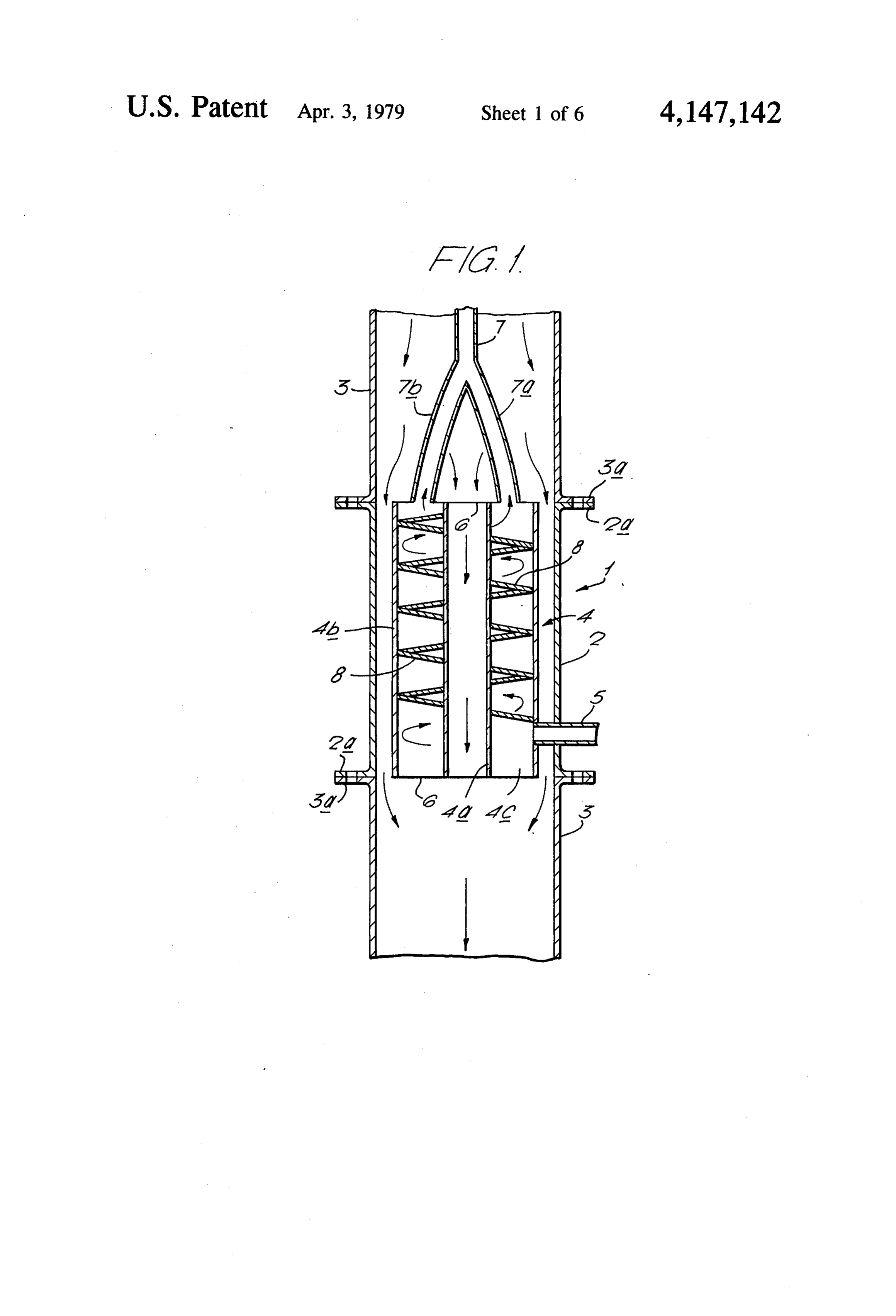
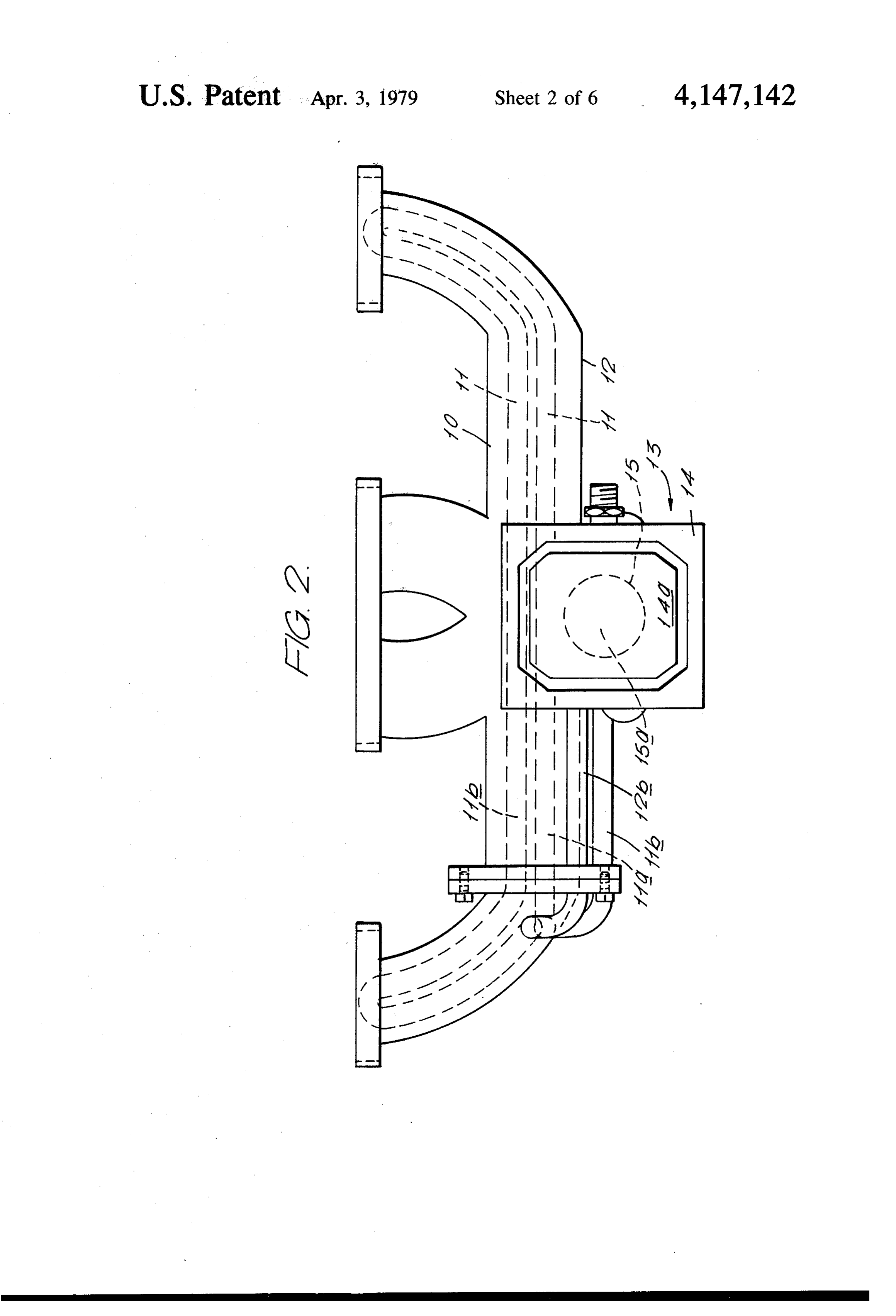
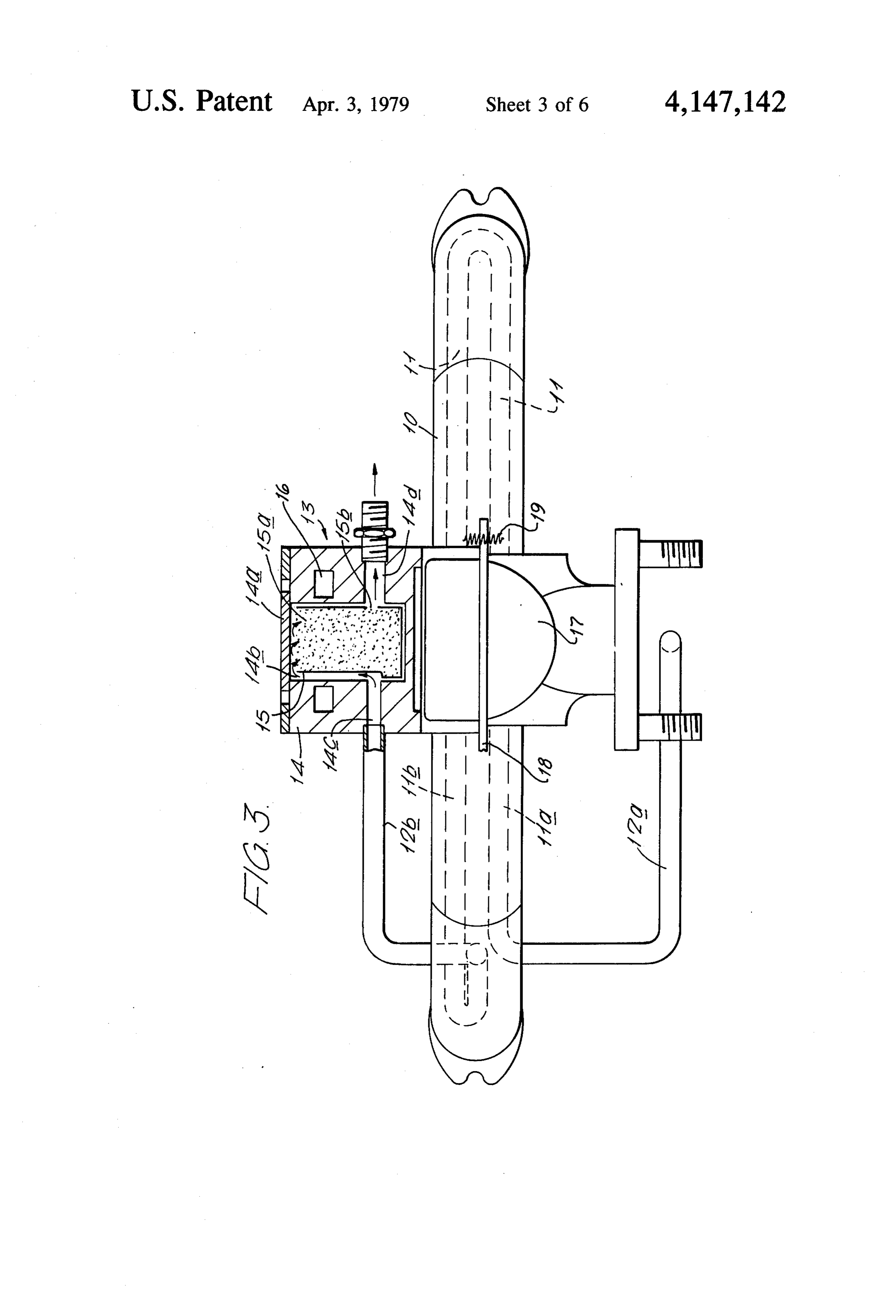
In order that the invention may be more readily un third housing outlet being connectable to the fuel induc 35 derstood tion system of the engine. further description thereof now will be pro In a further aspect there is provided an internal com vided with reference to the aspects and/or embodi bustion engine having a fuel induction system for meter ments shown in the accompanying drawings, in which; FIG. 1 shows a sectional view of a first stage fuel ing of gaseous hydrocarbon fuel to the engine, and a fuel modification means for cracking fuel received by modifier; FIG. 2 shows a plan view of second and third stage the induction system, the modification means including apparatus according to any one of the preceding aspects fuel modifiers;
or forms. FIG.3 shows a side elevation, partly in section, of the In one form, the engine has a fuel induction system modifiers of FIG. 2;
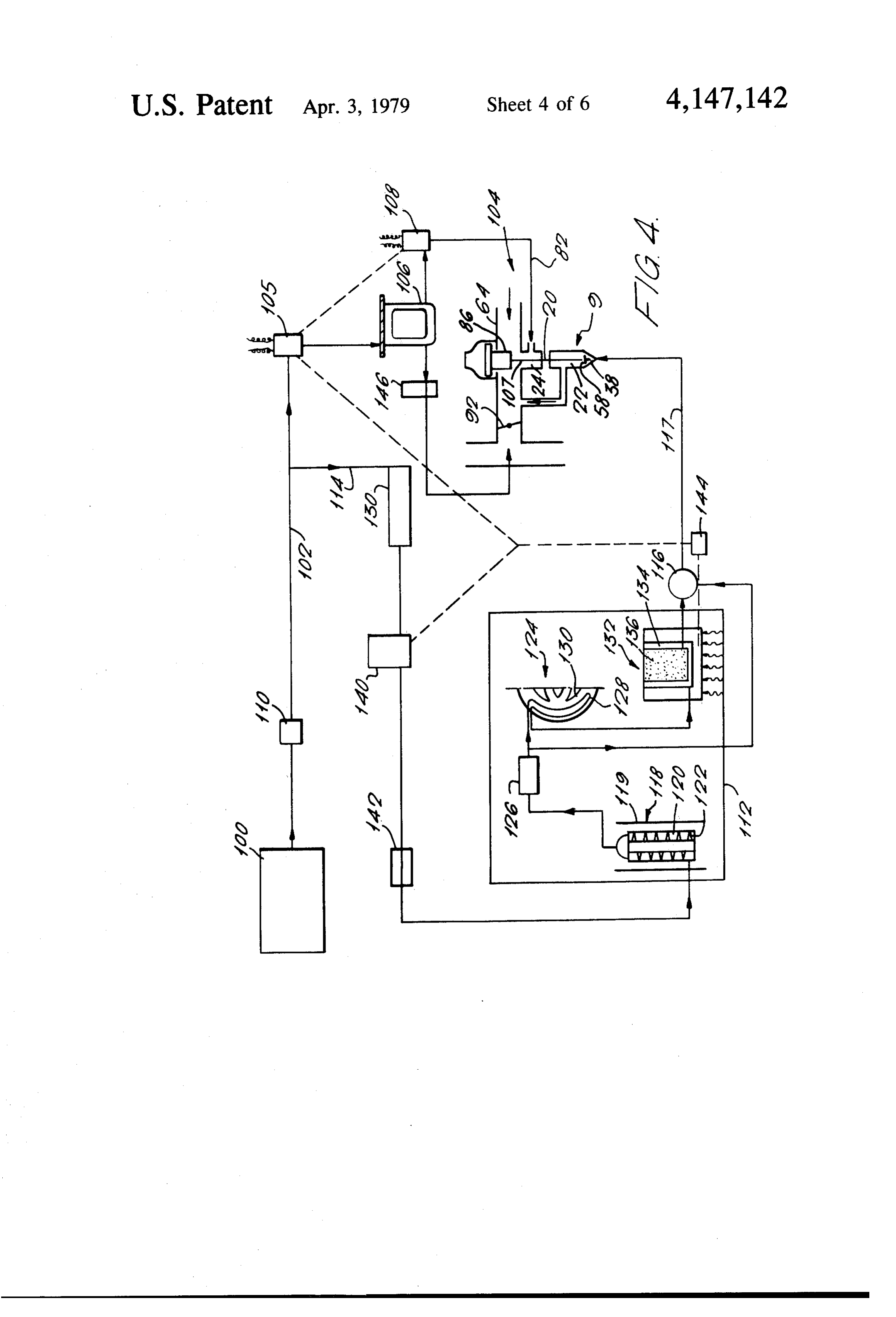
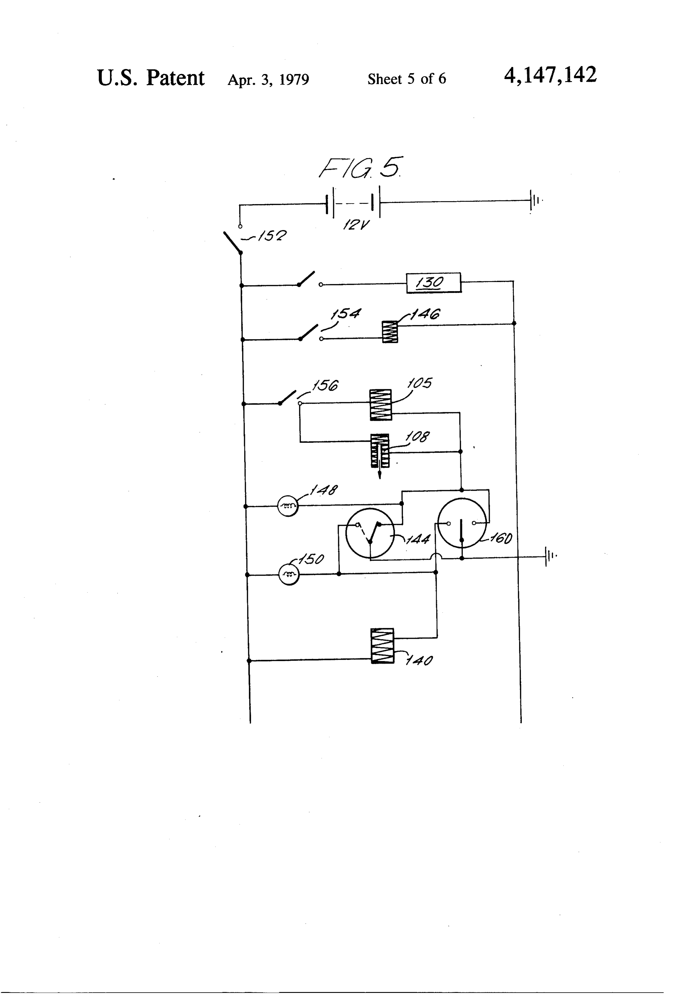
FIG. 4 is a schematic representation having three for metering of gaseous hydrocarbon fuel, a modified fuel supply system, and an exhaust system; the modified 45 modifier stages of the general form shown in FIGS. 1 to fuel supply system comprising a source for liquid hy 3; FIG. 5 is an ignition circuit for use with the system of drocarbon fuel, a first fuel modification stage for receiv ing fuel from the source and including a housing posi FIG. 4; and
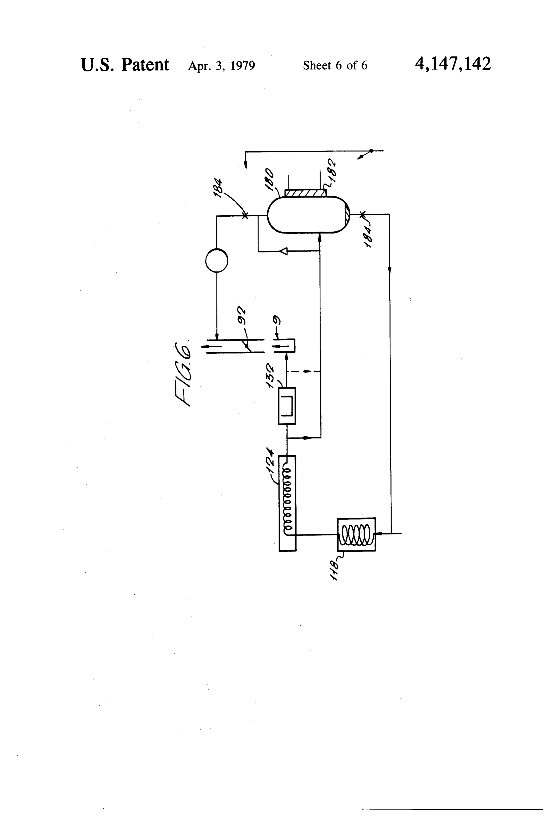
FIG. 6 is a schematic representation of a modified tioned for contact with hot exhaust gases of the engine 50 form of the system of FIG. 4. whereby fuel passing therethrough is vaporized and/or
With thermally cracked, a second fuel modification stage for fuel modifier reference to FIG. 1 there is shown a first stage receiving fuel from the first stage and including a hous gases in a separable 1 mounted for exposure to hot exhaust ing positioned for direct flame contact with exhaust portion of an exhaust outlet; portion gases of the engine whereby fuel passing therethrough 2 being connectable to pipes 3 of the exhaust outlet by is vaporized and/or thermally cracked, and a third fuel 55 flanges 2a, 3a.
modification stage for receiving fuel from the second anThe fuel modifier 1 comprises a container 4 defining annular chamber and having concentric inner and stage and including a housing for hydrocarbon fuel outer cylindrical walls 4a, 4b mounted within portion 2 cracking catalyst wherein fuel passing therethrough by means of an inlet pipe 5 which passes through the may be catalytically cracked; and means connecting the third stage to the fuel induction system for supply to the wall of portion 2 and communicates with the annular chamber through, and at one end of, outer wall 4b. The engine.
In such form of engine, there may be a fuel circuit for container is completed by two annular end plates 6, of by-passing the modified-fuel supply system for supply which the one remote from inlet pipe 5 is provided with of liquid fuel to the fuel induction system, the by-pass 65 substantially let pipe 7.
diamettrically opposed arms 7a, 7b of out circuit having associated therewith means responsive to Intermediate inlet and outlet pipes 5 and 7, the con engine operating temperature to close the by-pass cir cuit at a predetermined engine temperature and bring tainer 4 is provided with a helical baffle, defining within ing the modified-fuel system into communication with the annular chamber a tortuous flow path for fuel intro
Page 11
duced through inlet pipe 5. Under normal flow condi 14d, for combustion in an engine, via an opening 15b in tions for fuel introduced to the chamber through inlet pipe 5, baffle 8 can impart to the fuel a centrifugal force and towards the bottom of the canister and adjacent outlet 14d.
which enhances contact of spray formed by rapid boil The housing 14, mounted on exhaust manifold 12 off with surfaces of the container defining the chamber; such as by bolts, preferably is of a substantial thickness the latter being heated by hot exhaust gases which flow of a suitable metal and preferably is of heavy iron cast around wall 4b and through the core defined by wall 4a, construction. The housing 14 has formed in its wall The container, as indicated, has outlet 7 upstream with defining chamber 14b a duct 16 which extends around respect to the flow of exhaust gases. that chamber and communicates, via an inlet and outlet, The baffle 8 is spaced from the end plate 6 adjacent 10 with inlet pipe 5 to provide a small sub-chamber 4c. The in thethe interior of manifold 12 whereby exhaust gases manifold can flow around chamber 14b. A valve latter collects fuel condensate on cooling. 17, pivotable on shaft 18 under the action of thermostat Inlet pipe 5 is connectable to a source of fuel, such as spring 19, is operable to open and close duct 16 with petrol, to be modified; while outlet 7 is connectable to a respect to the interior of the manifold to thereby permit pipe for passing modified fuel issuing from the container 15 or prevent flow of exhaust gases around chamber 14b. to a further fuel modifier stage. The arrangement is such that until a predetermined First stage fuel modifier 1 is particularly suitable for temperature is attained in chamber 14b, and hence in modifying petrol by converting it to vapour. However, gaseous fuel passing from outlet 14d, spring 19 is opera depending on the temperature attainable, some thermal ble to hold valve 17 open to permit exhaust gases to cracking of the petrol also may be achieved. 20 flow induct 16 for rapid heating of housing 14 (heating The container 4 of fuel modifier 1 can be made of any suitable metal, although stainless steel generally is pre also being effected by fuel received through inlet 14c) and thereafter operable to close valve 17.
ferred. The walls preferably are of a light gauge mate On attainment of a required temperature, further rial to minimize the time for attainment of an equilib heating of housing 14 due to its mounting on manifold rium temperature and to enhance heat transfer. 25 12 is off-set by convection and radiation losses, such With reference to FIGS. 2 and 3, the second stage that the housing 14 acts as a heat sink for the high tem fuel modifier 10 comprises an elongate chamber 11 perature fuel passed thereto, preferably such. that the defined by a continuous length of ducting formed into a temperature of the modified fuel issuing therefrom sel pair of adjacent crescent shaped portions 11a, 11b. The dom rises about 200 C. During the heat-up period fol chamber 11 is located within an exhaust manifold 12 for 30 lowing engine start-up, any liquid fuel, which generally direct flame heating by exhaust gases; with the crescent shaped portions conforming usually to the outer curva willThebe housing condensate, will be vaporized.
14 can be provided with a palladium ture of the manifold. The free end of portion 11a com diffuser (not shown) for the selective separation of hy municates through the wall of the manifold with an inlet drogen which may be fed via a restrictor to the exhaust pipe 12a by which fuel to be modified, such as vapor 35 system containing catalytic reactors for the removal of ized and/or partly cracked fuel from the first stage, is oxides of nitrogen.
introduced into the chamber. The free end of portion Should the gases emerging from the third stage rise 11b communicates through the wall of the manifold above 200 C. under conditions of heavy load operation, with an outlet pipe 12b which receives from chamber 11 a bimetal valve, interposed between the third stage and fuel modified therein. the metering unit, will admit lower temperature fuel The chamber 11 may be made of any suitable metal, from the first stage until the temperature returns to 200 and preferably is of relatively heavy wall tubing.
The chamber is positioned as close as possible to the C. The valve is so constructed that fuel flows directly over the bimetal element at all times. Emerging fuel is exhaust of at least one of the branches of the manifold led directly to the lower chamber of the metering car for maximum heating. 45 burettor via a shut-off valve.
Fuel received in the second stage, such as from the first stage, is modified primarily by thermal cracking. temWith reference to FIG. 4, there is shown a fuel sys Some vapourization also can occur although this fuel line 102 toaapetrol including tank 100 connectable by a liquid carburettor system 104, via a solenoid largely will be of condensate. actuated valve 105, a float controlled fuel bowl 106 and The temperature of the exhaust gases within the man 50 a solenoid actuated needle valve 108. The line 102 ter ifold varies with engine loading and therefore tends to minates at a connector 82 for delivering liquid fuel to a provide differing thermal cracking conditions. This mostly is off-set by the fact that the residence time of first chamber 24, for liquid fuel, of a bifunctional fuel fuel vapours within chamber 11 is inversely related to application,device metering
Ser.
such as disclosed in our co-pending
engine load. 55 disclosure of which is incorporated herein by reference. With further reference to FIGS. 2 and 3, the third stage fuel modifier 13 consists of a housing 14 having a A low pressure fuel pump 110 in line 102 draws the petrol from the tank.
removable top 14a covering a centrally disposed cham Line 102 is connected downstream of pump 110 to a ber 14b in which is positioned a replaceable, open petrol vapourizer and/or cracker unit 112 by a branch topped canister 15 of filter supported hydrocarbon liquid-fuel line 114; with the outlet of unit 112 being cracking catalyst 15a, Toward the bottom of canister 15 connected via thermostat valve 116 to a second cham the housing 14 is provided with an inlet 14c, connected ber 22, for gaseous fuel, of the bifunctional fuel meter to outlet pipe 12b from the second stage, and an outlet ing device through gaseous fuel line 117. 14d substantially opposed to inlet 14c. Thus, modified The first fuel modifier stage 118 of unit 112 consists of fuel such as that received from the second stage can 65 a chamber pass into the chamber 14b wherein it flows upwardly to helical form,120orhaving therein a baffle for example of enter canister 15; and then flows downwardly through tortuous flow path. The primaryoffunction a multiplicity baffles 122 defining a the cracking catalyst in the latter to issue from outlet to vaporize petrol, although it can provideofastage 118 is measure of
Page 12
thermal cracking, and for this purpose it is heated by Operation of the system now will be described with hot exhaust gas such as by being positioned within an reference to FIGS. 4 and 5.
exhaust outlet 119. The carburettor system 9 may be mounted on a nor The second stage 124 of unit 112, comprises a heat mal engine inlet manifold, or, preferably, on a manifold able duct 128 and receives vaporized fuel, via a pressure 5 designed for gas flow alone rather than one designed to regulator 126, from stage 118. The vapourized fuel is cope with separated fuel spray. The manifold preferably further heated in duct 128, such as by duct 128 being should be completely separate from the exhaust system positioned in the exhaust manifold 130 to receive direct and the engine water cooling system i.e. no heated risers flame heating. or main tracts, and kept as cool as possible. The third stage 132 of unit 112 receives cracked va O The carburettor system utilizes the float controlled pour from the second stage. Stage 132 comprises a hous fuel bowl 106 for starting and warm-up, during which ing 133 defining a chamber 134 around which exhaust the solenoid needle valve 108, which may be mounted gases are passed, such as through ducting in the walls of on the bowl, provides control of petrol feed to the car housing 133, when the engine is cold but which is short burettor jet bridge 107, associated with the first fuel circuited of such gases after heat-up; the chamber 134 15 chamber, and controlled change-over to gaseous fuel. containing a cracking catalyst and filter 136 through The high pressure fuel pump 138 should be fitted with which the partly cracked vapour from chamber 134 is the a non-return valve, and preferably a pressure gauge, in passed. Chamber 134 also can contain a unit (not ing outlet from the pump to prevent gaseous fuel vent through the pump should the fuel pump cease to shown) comprising a palladium diffuser for selective 20 operate whilst the ignition switch and high pressure fuel separation of hydrogen, a restrictor valve from which the hydrogen may be fed, and catalytic reactors, for solenoid The are activated.
load sensing fuel flow controller 142 may be example, in the exhaust system, for removal of nitrogen mounted in any convenient position but preferably re oxides from the hydrogen fed thereto via the restrictor moved from exhaustheat. A diaphragm chamber of the valves.
Petrol is drawn into line 114 by means of a high pres 25 controller preferably is connected directly to the inlet manifold to permit monitoring of the engine load as sure pump 138 and passes to unit 112 via a solenoid indicated valve 140 and flow controller 142 sensitive to engine flow from by pressure in that manifold for control of pump 138 to unit 112 and the second, gaseous load. fuel chamber 22.
The third stage 134 has associated therewith a ther 30 Suitable electrical connections are shown in the wir mo-switch 144 which is electrically connected, as ing diagram of FIG. 5. As indicated in FIG. 5, warning shown in FIG. 4 by broken lines, to solenoid needle lamps 148, 150 indicate which of liquid or gaseous fuel valve 108, via solenoid valve 105, and to solenoid valve systems, respectively, is operating, or will operate, 140. During engine operation on liquid fuel, such as before attainment of a predetermined engine tempera 35 when switch 152 of the ignition circuit is closed. For start-up and drive away in cold conditions, the ture as detected by switch 144, the switch 144 actuates ignition circuit switch 152 is closed; the "choke' switch solenoid valve 140 to close and actuates solenoid valves 154 is closed or the mechanical starting carburettor 105 and 108 to open to permit flow of liquid petrol to valve is operated; and the "manual off switch 156 is float valve 106 and from the latter to the liquid fuel closed; after which the "spray fuel” lamp 148 will indi chamber 24 of the carburettor system. For cold start-up cate. With manual override switch 160 in the "off liquid petrol then passes direct to the inlet manifold 64 position, a switch 161 of the high pressure fuel pump is or just downstream of throttle butterfly valve 92 of the actuated. The engine then is cranked with the starter carburettor system via electrically or mechanically motor and, after the engine fires, the choke switch 154 operable auxiliary start-up valve 146. For operation on is opened. The engine now runs normally on the spray cracked petrol vapour on attainment of the predeter 45 function of the carburettor being fed liquid fuel from mined engine temperature, switch 144 actuates solenoid the low pressure fuel pump via the spray fuel solenoid valve 105 and 108 to close to terminate flow to the first and needle valves; these being activated by the position chamber 24, and actuates valve 140 to open to pass of the thermo-switch 144 inserted e.g. in the exhaust petrol to unit 112 for generation of cracked petrol va manifold.
pour to be passed to the second, gaseous fuel chamber 50 The vehicle can now be driven away. From the in 22 of the carburettor system. Solenoid valves 105, 108 stant of starting, the three stages of the fuel modification and 140 thus, positively isolate the parts of the system unit 112 heat rapidly, particularly with the engine under used for liquid fuel or gaseous fuel operation and which load. During this heat up period, condensed fuel in unit are not required at any particular time; i.e., during 112 from previous operation is vapourized and expelled warm-up or, in the event of malfunction, to isolate the 55 from the gas port in the carburettor since, as long as the defective part. engine is operating, a cracked gaseous fuel shut-off In an alternative form, switch 144 may be of a type valve member 58 controlling feed to the second fuel operable, in dependence on the pressure of gaseous fuel chamber is free to lift off its seat 38. At a predetermined available for supply to fuel chamber 2, to control valves temperature, governed e.g., by catalyst chamber re 105,108 and 140; the latter being electrically, electro quirement and fuel boiling range, the thermoswitch 144 mechanically, pneumatically or hydraulically operable. shuts off the spray fuel supply, simultaneously feeding Thus, if available gaseous fuel pressure is below a prede fuel to the first stage modifier 118 for vapourization. termined level, switch 144 will close valve 140 and open Pressure rises rapidly throughout the whole system, valves 105 and 108 for engine operation on liquid fuel whereupon cracked gaseous fuel commences to flow to via chamber 24 and, when gaseous fuel pressure exceeds 65 chamber 22 at exactly the required rate predisposed by the predetermined level, it will close switches 105 and the position of the air valve 86 which monitors the 108 and open switch 140 for engine operation on gase engine speed and load at all times and, hence, the degree ous fuel via chamber 22. to which valve member is lifted from seat 38 with nee
Page 13
dle 20. It is therefore of no importance whether the valve admits some fuel gas directly from the cooler first switch-over point is reached at no load (idling), light stage 118 to the outlet line of the third stage, for admix load, or heavy load conditions; temperature being the ture therein, to prevent the occurrence of lean mixtures parameter determing switch-over. A smooth change and adverse effects on volumetric efficiency. over without loss of power, or misfiring is affected. The fuel system as described and without substantial For as long as the major components retain consider modification, can be used as a metering carburettor for able heat, pressure will be retained within the gas injec LPG. The usual pressure control equipment (dia tion system. The metering needle 20, common to cham phragm regulator and anti-freeze heat exchanger) can bers 22 and 24, will cause the shut-off valve member 58 be used and the LPG then fed directly to the gas shut to rest on its seat 38 at the inlet to chamber 22 and all 10 off valve 58. Alternatively, the gas can be fed directly electrically operated valves will be closed with the into the inlet of the cracking system of unit 112. ignition off. On hot restart, cranking the engine causes Servicing and maintenance of the unit 112 is mainly the air valve 86 to lift thus freeing the gas shutoff valve confined to checking the catalyst for excessive carbon member 58. Cracked gaseous fuel pressure within the build up and possible choking of the system. This latter system lifts the needle from its seating, and the gaseous 15 is readily detected by placing a pressure gauge on each fuel is discharged into the inspired air induct 64 and the side of the third stage catalyst chamber and observing engine fires immediately. whether there is a significant pressure drop during nor For warm restart after pressure drop within the gase mal operation.
ous fuel system, the thermoswitch may have returned The canister can be renewed quickly and easily by the system to spray operation. In this case subsequent removing the bolt-on lid from its cast housing. events will be the same as cold start except that there will be no need for "choke' operation i.e. the engine functionality, its ownincorporates,
The carburettor
because of its dual system. Should malfunc should fire on the spray system.
If, however, the thermoswitch has not reset for oper unit 112, opening of the high-pressure fuel pumpcracking tion occur in the fuel vapourization and/or ation of the spray system, fuel spray operation can be 25 and manual setting of the override switch, can circuit achieved for a short period by use of the manual over the carburettor to spray operation immediately.return The ride switch 160 shown in the wiring diagram. As soon as vehicle can be driven unlimited distance before over full gaseous fuel pressure is achieved the switch can be haul of the gas system.
returned to the "off’ position. The general system such as shown in FIG. 4 may be No special procedures are required for shut-down. 30 used
The engine may be stopped without lowering the fuel poorerforquality the vapourization and thermal cracking of fuels of much higher flash point and pressure. Condensation in unit 112 occurring during initial boiling point. Such a use is of advantage where cooling can assist in getting the vehicle away after a regulations prohibit the use of petrol (gasoline) engines cold restart since this fuel vapourizes during warm-up and enriches the spray mixture. It therefore allows the 35 Where these fuels may to and restrict power plants those of the diesel type.
be used in spark-ignition en use of a "lean profile' taper on the spray metering ta pered section at bridge 107 of the metering needle 20 gines (after modification according to the described associated with chamber 24. method of this invention), the attainment of a suitably vapourized fuel/air mixture for restarting could present
In one form of the system of FIG. 4, the low pressure difficulties.
fuel pump 110 delivers petrol at 2 PSIG or higher and may comprise a standard electrical or mechanical fuel Electric heaters within, for example, the starting pump of the conventional carburettor fitted engine. carburettor section could provide a solution but by the High pressure fuel pump 138 also may be electrical or provision of an additional, accumulation chamber, con mechanical, and preferably has a non-return valve in its nected in parallel between the second and third stage outlet and delivers petrol at 30 PSIG or higher. The 45 cracking chambers or between the third stage and the flow controller 142 preferably is a vacuum system dia metering unit, the system can provide for restart condi phragm valve which allows full fuel flow except at tions following normal temperature operation. A modi times of closed-throttle operation, i.e., idling or closed fied system having such chamber now will be described throttle overrun, with fuel flow in the latter case being with reference to FIG. 6, wherein like parts have the restricted by adjustable by-pass valve 143. 50 same reference numerals as in FIG. 4. The fuel system is capable of supplying an engine The function of the chamber, and the means by which with a substantially constant fuel/air ratio over the it may be incorporated in the system of FIG. 4, is as whole range of speed and load requirements by func follows:
tioning primarily as a gas/gas metering system in place Hot gaseous fuel is led into the accumulation cham of the usual gas/liquid system. 55 ber 180 at normal operating pressure. The chamber may Operation of the system can be achieved without pres be provided with either water or air cooling means 182, sure regulator 126 but not without hunting at wide whereupon condensable compounds settle out and are throttle openings due to the rapid change in volume of allowed to return, via suitable valves 184, to the first fuel entering the vapourizer. Pressure fluctuations are stage evaporator. During operation of the engine, non damped out by running the high pressure fuel injector 60 condensable gases will accumulate within the chamber, pump 138 at a pressure above that at which the meter until a point is reached where no further cracked fuel ing section is designed to operate, then reducing it to a will enter the chamber, i.e. when the pressure of the desired pressure of approximately 15 PSIG. non-condensable gases equilibrates to the pressure of Bimetal thermostatic valve 116 comprises a small operation.
chamber containing a bimetal spiral actuating a rotary 65 At engine shut-down, isolation valves 184 attached to valve. This is interposed between the third stage 132 the accumulator, may be closed, e.g. electromagneti modifier and the carburettor system. If fuel from the cally, thereby leaving the system charged with gaseous third stage rises above about 200 C., for example, the fuel for restarting.
Page 14
The cold restarting procedure then requires a modifi (3) hot LPG or cation of that suggested for volatile fuels and in particu (4) cold (direct) LPG lar could provide for short-period supply (after initial Finally, it is to be understood that various alterations, restart on accumulator gas) of vapourized fuel directly modifications and/or additions may be introduced into from Stage 2 to a metering orifice on the engine side of 5 the constructions and arrangements of parts previously the carburettor butterfly valve. described without departing from the spirit or ambit of Control of the valves required for this operation can the invention.
be governed by the thermo-switch in an exactly similar The claims defining the invention are as follows: manner to that described for initial fuel spray operation 1. An internal combustion engine having a fuel supply using volatile fuels (FIG. 4). O system; a fuel induction system; an exhaust system in It will be appreciated that apart from the very short cluding an exhaust manifold and an exhaust discharge chain hydrocarbons like methane and ethane, thermal conduit; and means for modifying fuel supplied to the cracking produces a variety of hydrocarbons. The en engine; said fuel modifying means comprising: a first ergy available from the combustion of the cracked 15 fluid chamber having, an inlet and an outlet for passage of products is higher than that from the combustion of the hydrocarbon fuel therethrough; said first chamber original uncracked fuel of equivalent carbon and hydro having a tortuous, labyrinth path for the fuel flow from gen composition. This is directly reflected in the chemi said inlet to said outlet; said first chamber being incor cal bond energies of the otherwise equivalent fuels and porated in said exhaust discharge conduit and being is the direct result of restoring, endothermically, some 20 adapted for external heating by the exhaust in said ex of the waste exhaust heat into the incoming fuel. haust discharge conduit whereby fuel received at said Further use can be made of the large amount of waste inlet as a liquid is thermally cracked during flow to said heat available to produce even further quantities of outlet; a second chamber having an inlet and an outlet; hydrogen through the reaction of water with hydrocar said second chamber inlet being in communication with bons under heat-controlled catalytic conditions, ac 25 said first chamber outlet for receiving fuel from said cording to the equation: first chamber, said second chamber outlet being in com munication with said fuel induction system for the sup ply of fuel thereto; said second chamber containing a cracking catalyst for hydrocarbon fuel; and said second
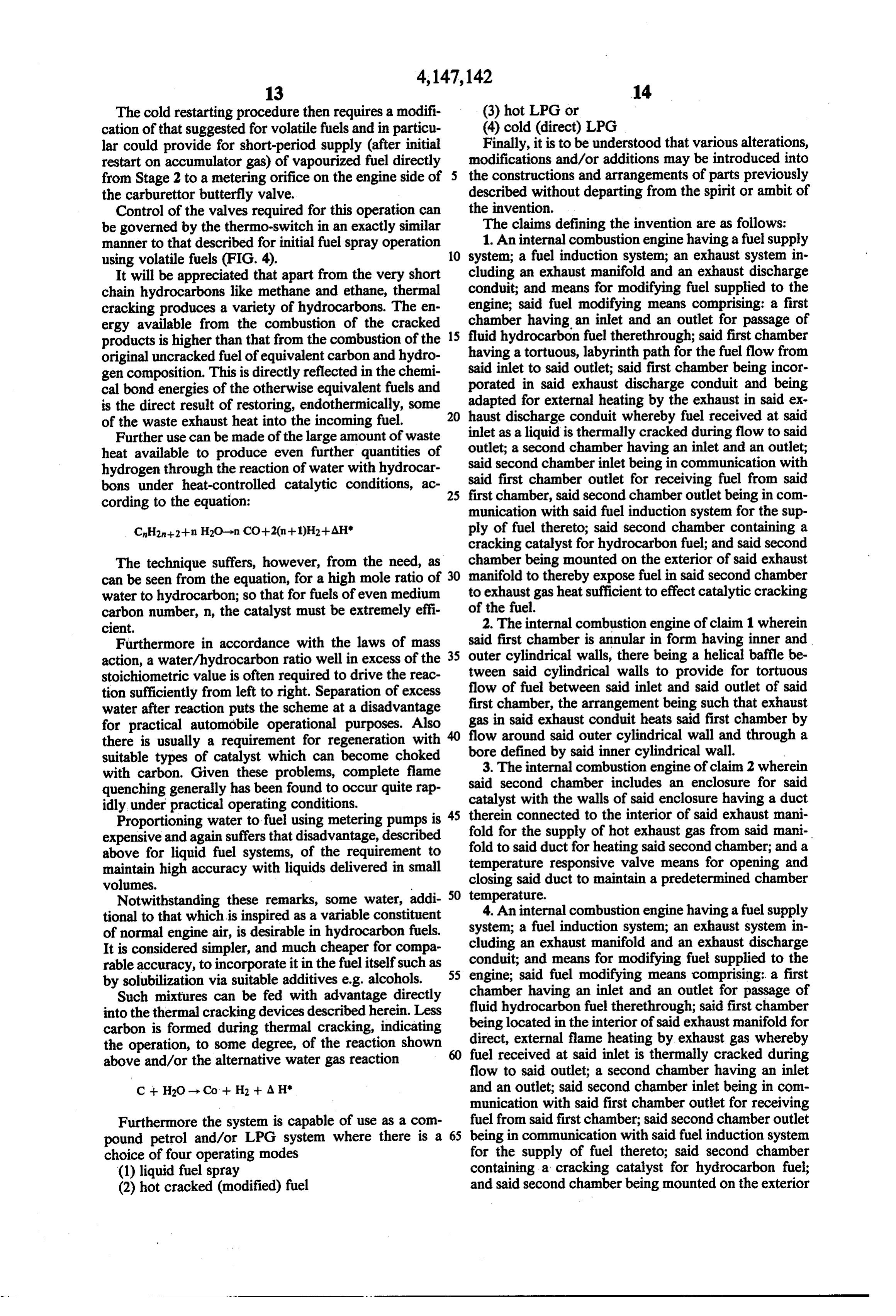
The technique suffers, however, from the need, as chamber being mounted on the exterior of said exhaust can be seen from the equation, for a high mole ratio of 30 manifold to thereby expose fuel in said second chamber water to hydrocarbon; so that for fuels of even medium to exhaust gas heat sufficient to effect catalytic cracking carbon number, n, the catalyst must be extremely effi of the fuel.
cient. 2. The internal combustion engine of claim 1 wherein Furthermore in accordance with the laws of mass said first chamber is annular in form having inner and action, a water/hydrocarbon ratio well in excess of the 35 outer cylindrical walls, there being a helical baffle be stoichiometric value is often required to drive the reac tween said cylindrical walls to provide for tortuous tion sufficiently from left to right. Separation of excess flow of fuel between said inlet and said outlet of said water after reaction puts the scheme at a disadvantage first chamber, the arrangement being such that exhaust for practical automobile operational purposes. Also gas in said exhaust conduit heats said first chamber by there is usually a requirement for regeneration with flow around said outer cylindrical wall and through a suitable types of catalyst which can become choked bore 3.
defined by said inner cylindrical wall.
The internal combustion engine of claim 2 wherein with carbon. Given these problems, complete flame said second chamber includes an enclosure for said quenching generally has been found to occur quite rap idly under practical operating conditions. catalyst with the walls of said enclosure having a duct Proportioning water to fuel using metering pumps is 45 therein connected to the interior of said exhaust mani expensive and again suffers that disadvantage, described fold for the supply of hot exhaust gas from said mani above for liquid fuel systems, of the requirement to temperaturefold to said duct for heating said second chamber; and a maintain high accuracy with liquids delivered in small closing said duct responsive valve means for opening and volumes. to maintain a predetermined chamber Notwithstanding these remarks, some water, addi 50 temperature. 4. An internal combustion engine having a fuel supply tional to that which is inspired as a variable constituent system; a fuel induction system; an exhaust system in of normal engine air, is desirable in hydrocarbon fuels.
It is considered simpler, and much cheaper for compa cluding an exhaust manifold and an exhaust discharge rable accuracy, to incorporate it in the fuel itself such as 55 conduit; and means for modifying fuel supplied to the engine; said fuel modifying means comprising: a first by solubilization via suitable additives e.g. alcohols. chamber having an inlet and an outlet for passage of Such mixtures can be fed with advantage directly fluid hydrocarbon fuel therethrough; said first chamber into the thermal cracking devices described herein. Less being located in the interior of said exhaust manifold for carbon is formed during thermal cracking, indicating the operation, to some degree, of the reaction shown 60 direct, external flame heating by exhaust gas whereby fuel received at said inlet is thermally cracked during above and/or the alternative water gas reaction flow to said outlet; a second chamber having an inlet
C + H2O - Co -- H2 + A H' and an outlet; said second chamber inlet being in com munication with said first chamber outlet for receiving
Furthermore the system is capable of use as a com fuel from said first chamber; said second chamber outlet pound petrol and/or LPG system where there is a 65 being in communication with said fuel induction system choice of four operating modes for the supply of fuel thereto; said second chamber (1) liquid fuel spray containing a cracking catalyst for hydrocarbon fuel; (2) hot cracked (modified) fuel and said second chamber being mounted on the exterior
Page 15
of said exhaust manifold to thereby expose fuel in said 11. An internal combustion engine having a fuel in second chamber to exhaust gas heat sufficient to effect duction system for metering of gaseous hydrocarbon catalytic cracking of the fuel. fuel to the engine; a exhaust system including an exhaust 5. The internal combustion engine of claim 4 wherein manifold and an exhaust discharge conduit; and means said first chamber comprises an elongate conduit which for modifying fuel supplied to the engine; said fuel mod extends at least once between opposed ends of said ifying means comprising a chamber located in said ex exhaust manifold and is in close proximity to at least one haust conduit having an inlet for receiving liquid fuel inlet branch of said manifold. from a fuel supply for the engine and an outlet for pas 6. An internal combustion engine having a fuel supply sage of fluid hydrocarbon fuel therethrough to said system; a fuel induction system; an exhaust system in 10 induction system; said chamber being of an annular cluding an exhaust manifold and an exhaust discharge form having an outer encircling wall and an inner wall conduit; and means for modifying fuel supplied to the spaced from said outer encircling wall, with said inlet engine; said fuel modifying means comprising: first, and said outlet being adjacent a respective end of said second and third chambers; each of said chambers hav chamber; there being a helical baffle extending through ing an inlet and an outlet; said outlet of said first cham 15 said chamber between said outer wall and said inner ber being in communication with said inlet of said sec wall to define a tortuous, labyrinth path for the flow of ond chamber; said outlet of said second chamber being fuel from said inlet to said outlet; the chamber being in communication with said inlet of said third chamber; adapted for external heating in said exhaust conduit by said outlet of said third chamber being in communica flow of exhaust gas over said outer wall and through a tion with said fuel induction system whereby fuel passes 20 bore defined by said inner wall whereby fuel received as from said first chamber to said second chamber to said a liquid at said inlet of said chamber is vaporized and third chamber and then to said fuel induction system; thermally cracked during flow to said outlet thereof. said first chamber having a tortuous, labyrinth path for 12. An internal combustion engine having a fuel in the fuel flow from its inlet to its outlet; said first cham duction system for metering of gaseous hydrocarbon ber being incorporated in said exhaust discharge con 25 fuel; a fuel modification system; an exhaust system in duit and being adapted for external heating by the ex cluding an exhaust manifold and an exhaust conduit; haust in said exhaust discharge conduit whereby fuel said fuel modification system comprising a first fuel received at said first chamber inlet as a liquid is vapor modification stage for receiving fuel from a source of ized during flow to said first chamber outlet; said sec liquid hydrocarbon fuel and including a housing posi ond chamber being located in the interior of said ex 30 tioned in said exhaust conduit for contact with hot ex haust manifold for direct, external flame heating by haust gases of said engine whereby fuel passing there exhaust gas whereby fuel received at said second cham through is vaporized and thermally cracked; a second ber inlet is thermally cracked during flow to said second fuel modification stage for receiving fuel from said first chamber outlet; said third chamber containing a crack stage and including a housing positioned within said ing catalyst for hydrocarbon fuel; said third chamber 35 exhaust manifold for direct flame contact with exhaust being mounted on the exterior of said exhaust manifold gases of said engine whereby fuel passing therethrough to thereby expose fuel in said third chamber to exhaust is thermally cracked; and a third fuel modification stage gas heat sufficient to effect catalytic cracking of the for receiving fuel from said second stage and including fuel. a housing for hydrocarbon fuel cracking catalyst 7. An engine according to claim 6 and including an mounted on said exhaust manifold exteriorly thereof accumulation chamber for storing gaseous hydrocarbon wherein fuel passing therethrough may be catalytically fuel that is non-condensible at ambient temperature; and cracked; and means connecting said third stage to said a first conduit providing the communication between fuel induction system for supply of modified fuel to said said second chamber and said third chamber and a sec engine.
ond conduit providing the communication between said 45 13. An engine according to claim 12, including a fuel third chamber and said fuel induction system; said accu circuit for bypassing said fuel modification system for mulation chamber having an inlet in communication supply of liquid fuel directly to said fuel induction sys with at least one of said first conduit and said second tem on engine start-up; said bypass circuit having asso conduit and an outlet providing communication be ciated therewith means responsive to engine operating tween said accumulation chamber and said fuel induc 50 temperature for closing the bypass circuit at a predeter tion system, whereby a portion of the fuel is accumu mined engine temperature and bringing said fuel modifi lated in said accumulation chamber during normal oper cation system into communication with said induction ation of the engine for use in a subsequent start-up of the system.
engine until attainment of a predetermined engine tem 14. An engine according to claim 13 wherein said perature. 55 bypass circuit and said fuel modification system each 8. An engine according to claim 7 wherein said accu has a control valve; said means responsive to operating mulation chamber has a further outlet for recycling any temperature being a thermal-switch adapted to close condensed fuel accumulating therein; said further outlet and open said bypass circuit valve and open and close being in communication with said inlet of said first said fuel modification system valve in dependence on chamber. the engine temperature being at or below a predeter 9. An engine according to claim 7, wherein said accu mined temperature.
mulation chamber is provided with cooling means for 15. An engine according to claim 14 wherein said cooling fuel supplied thereto and thereby separating bypass circuit includes a float controlled fuel bowl for condensible and non-condensible fractions of such fuel. receiving fuel from said source of liquid hydrocarbon 10. An engine according to claim 6 wherein a conduit 65 fuel via said bypass circuit valve; said induction system provides the communication between said first chamber having a jet bridge; said bypass circuit having a second and said second chamber and said conduit extends control valve; and said float controlled fuel bowl within said exhaust system. supplies fuel to said jet bridge via said second control
Page 16
valve which is openable and closable with opening and haust manifold; a fuel supply for the engine and a fuel closing of said first bypass circuit valve. modification means for cracking fuel to be received by 16. An engine according to claim 15, wherein said the induction system; the modification means compris bypass circuit has a line providing communication be ing a housing defining a chamber having an inlet for tween said fuel bowl and said induction system; said line receiving fuel from said fuel supply and an outlet for having a valve therein operable on engine start-up to passage of fluid hydrocarbon fuel therethrough to said supply reserve fuel to said induction system. induction system; said housing being an elongate con 17. An engine according to claim 12, wherein said duit disposed in said exhaust manifold and extending at means connecting said third fuel modification stage to least once between opposed ends of said exhaust mani said induction system includes a needle and a gaseous 10 fold, said housing being in close proximity to at least fuel metering chamber; said needle controlling said one inlet branch of said manifold for direct, maximum gaseous fuel metering chamber; said needle being mov external flame heating whereby fuel received at said able for variation of the volume of metered gaseous fuel inlet is thermally cracked during flow to said outlet. in dependence on pressure within said induction system. 25. An internal combustion engine having a fuel in 18. An engine according to claim 17 including a fuel 5 duction system for metering of gaseous hydrocarbon circuit for bypassing said fuel modification system for fuel to the engine; an exhaust system including an ex supply of liquid fuel directly to said fuel induction sys haust manifold; a supply of liquid fuel for the engine and tem on engine start-up wherein said bypass circuit has a a fuel modification means for cracking fuel to be re liquid fuel metering chamber and said needle is common ceived by the induction system; the modification means to said gaseous fuel metering chamber and to said liquid 20 comprising means for converting fuel from said supply fuel metering chamber to provide a bifunctional carbu to a gaseous form and a housing containing a dehydro rettor system operable with fuel of either of said fuel genation cracking catalyst for hydrocarbon fuel; said modification system and said bypass circuit to supply a housing having an inlet by which fuel is receivable from respective one of gaseous and liquid fuel to said induc 25 said fuel converting means and an outlet communicat tion system in dependence on pressure in said induction ing with said fuel induction system of the engine; said system. housing being defined by a heavy-walled metal enclo 19. An engine according to claim 18, wherein said sure for the catalyst mounted on said exhaust manifold; gaseous fuel metering chamber has an inlet; said needle the walls of the enclosure having a duct therein in com has a tapered portion at said gaseous fuel metering munication with the interior of said manifold for the chamber inlet for controlling the volume of gaseous fuel 30 supply of hot exhaust gas from said manifold to said received therein, said gaseous fuel metering chamber duct as a means of supplying heat to fuel received by having an outlet in communication with said induction said housing from said fuel converting means; there system which bypasses said liquid fuel metering cham being temperature responsive valve means for control ber. ling flow of exhaust gas from the manifold through said 20. An engine according to claim 12 and including 35 duct and operable, on attainment of a predetermined accumulation means for receiving from said fuel modifi housing cation system a portion of the gaseous hydrocarbon fuel hydrogentemperature at which said catalyst liberates which is non-condensible at ambient temperature and and close said duct tofor from the fuel supply to the engine, to open control such flow for mainte for supplying the gaseous hydrocarbon fuel for use in a subsequent start-up of the engine until attainment of a nance 26.
of said predetermined temperature.
An internal combustion engine having a fuel in predetermined engine temperature. duction system for metering of gaseous hydrocarbon 21. An engine according to claim 20 wherein said accumulation means includes an accumulation chamber fuel to the engine; an exhaust system including an ex for storing gaseous hydrocarbon fuel that is non-con haust means manifold and an exhaust discharge conduit; and for modifying fuel supplied to the engine; said
densible at ambient temperature; a first conduit provid fuel modifying ing the communication between said second stage and ings each defining means comprising first and second hous said third stage and a second conduit providing the and an outlet, witha respective chamber having an inlet communication between said third stage and said fuel being in communication with saidofinlet said outlet said first chamber of said second induction system; said accumulation chamber having an 50 chamber; said first chamber being incorporated inlet in communication with at least one of said first discharge conduit, and having therein a tortuous,inlaby said conduit and said second conduit and an outlet providing communication between said accumulation chamber rinth path for fuel flow from said inlet to said outlet thereof; said first chamber being adapted for external and said fuel induction system whereby a portion of the heating fuel is accumulated in said accumulation chamber dur by exhaust gas in said discharge conduit whereby ing normal operation of the engine for use in a subse and thermally 55 fuel received at said inlet thereof is vaporized quent start-up of the engine until attainment of a prede second housingcracked being during flow of said outlet; said disposed interiorly of said exhaust termined engine temperature. manifold for direct, external flame heating by exhaust 22. An engine according to claim 21 wherein said gas, whereby fuel received at said second accumulation chamber has a further outlet for recycling is further thermally cracked during flow tochamber inlet any condensed fuel accumulating therein; said further chamber outlet for supply to said inductionsaid second system.
outlet being in communication with said first stage.
23. An engine according to claim 21, wherein said 26,27.wherein An internal combustion engine according to claim said second housing is in the form of an accumulation chamber is provided with cooling means for cooling fuel supplied thereto and thereby separating elongate conduit extending at least once between op condensible and noncondensible fractions of such fuel. 65 posed ends of said exhaust manifold; said elongate con 24. An internal combustion engine having a fuel in duit extending in close proximity to at least one of the duction system for metering of gaseous hydrocarbon inlet branches of said exhaust manifold for maximum fuel to the engine; an exhaust system including an ex flame heating thereat.
Page 17
28. An engine according to claim 27, wherein said 31. An internal combustion engine according to claim first housing is defined by inner and outer cylindrical 30, wherein said second chamber is an elongate duct, a walls and a respective annular end wall across each end portion of which conforms to the curvature of said of an annular chamber defined between said cylindrical exhaust manifold and a second portion of which is in walls; there being a helical baffle between and coaxial close proximity to at least one of the inlet branches of with said cylindrical walls to provide for tortuous flow said exhaust manifold for maximum flame heating. of fuel between said inlet and said outlet of said first 32. An engine according to claim 31 wherein said housing; the arrangement being such that exhaust gas in first, second and third chambers are all spaced from one said exhaust conduit heats said first chamber by flow another.
around said outer cylindrical wall and through a bore 10 33. The internal combustion engine of claim 24 defined by said inner cylindrical wall. wherein said housing extends at least once across the 29. An internal combustion engine according to claim inlet ports of said manifold.
6 wherein said first chamber includes inner and outer 34. The internal combustion engine of claim 25 in concentric cylindrical walls and two annular end walls cluding means for the selective separation of the hydro between said concentric cylindrical walls at the ends 15 gen formed by said cracking catalyst; said exhaust sys thereof; said first chamber inlet positioned at one end of tem containing a catalytic reactor for the removal of said cylindrical walls and said first chamber outlet posi nitrogen oxides; and means for feeding said hydrogen to tioned at the opposite end of said cylindrical walls; and said catalytic reactor.
a helical baffle between and coaxial with respect to said 35. The internal combustion engine of claim 5 cylindrical walls whereby said tortuous, labyrinth path 20 wherein said second chamber includes an enclosure for for fuel flow between said inlet and said outlet is pro said catalyst with the walls of said enclosure having a vided. duct therein connected to the interior of said exhaust 30. An internal combustion engine according to claim manifold for the supply of hot exhaust gas from said 29 wherein said first chamber is longitudinally disposed manifold to said duct for heating said second chamber; within said exhaust discharge conduit whereby exhaust 25 and a temperature responsive valve means for opening gas in said conduit heats said first chamber by flow and closing said duct to maintain a predetermined around said outer cylindrical wall and through an open chamber temperature.
bore defined by said inner cylindrical wall.
Provenance
- Collection
- Cited prior art
- Original PDF
- patentimages.storage.googleapis.com →
- Filed
- 1976-03-12
- Pages
- 17
- Method
- pdftotext (the PDF's own text layer) + pdftoppm 300dpi page scans
- Source
- Google Patents bibliographic record
- Granted
- 1979-04-03
- Inventors
- Allan V. Little, deceased; administratrix by Anna Little; Ronald A. Wilkinson
- Transcribed from
- patentimages.storage.googleapis.com →