patent · US5604607A
Light concentrator system
18 February 1997
Page 1 — bibliographic record
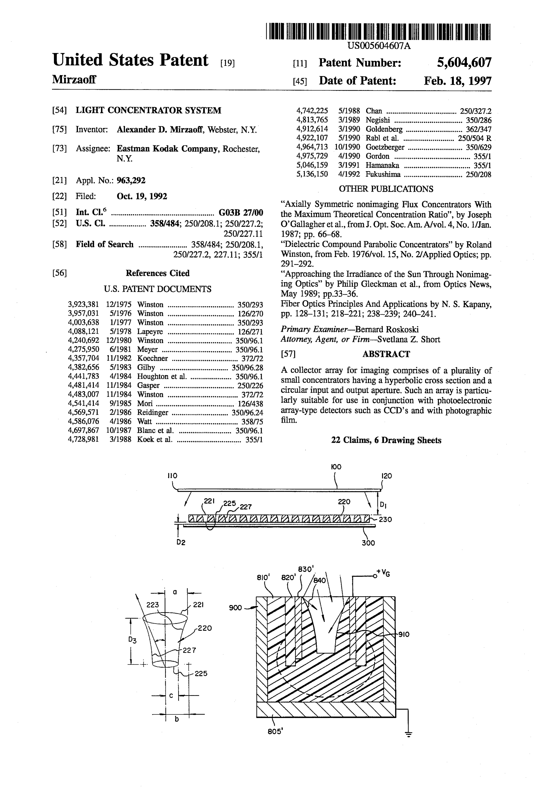
United States Patent (19) 11 Patent Number: 5,604,607 Mirzaoff 45) Date of Patent: Feb. 18, 1997 54) LIGHT CONCENTRATOR SYSTEM 4,742,225 5/1988 Chan .................................... 250/327.2 4,813,765 3/1989 Negishi ................................... 350/286 (75) Inventor: Alexander D. Mirzaoff, Webster, N.Y. 4,912,614 3/1990 Goldenberg ... 362/347 4,922,107 5/1990 Rablet al. ..... 250/504 R (73) Assignee: Eastman Kodak Company, Rochester, 4,964,713 10/1990 Goetzberger ............................ 350/629 N.Y. 4,975,729 4/1990 Gordon ....................................... 355/1 5,046,159 3/1991 Hamanaka .................................. 355/1 5,136,150. 4/1992 Fukushima .............................. 250/208
OTHER PUBLICATIONS
"Axially Symmetric nonimaging Flux Concentrators With 51 Int. Cl. ... G03B 27100 the Maximum Theoretical Concentration Ratio", by Joseph 52) U.S. Cl. ................... 358/484; 250/208.1; 250/227.2; O'Gallagher et al., from J. Opt. Soc. Am. A/vol. 4, No. 1/Jan.
58) Field of Search ......................... 358/.484; 250/208.1, "Dielectric Compound Parabolic Concentrators' by Roland 250/227.2, 227.11; 355/1 Winston, from Feb. 1976/vol. 15, No. 2/Applied Optics; pp.
(56) References Cited "Approaching the Irradiance of the Sun Through Nonimag
3,923,381 12/1975 Winston .................................. 350/293 Fiber Optics Principles And Applications by N. S. Kapany, 3,957,031 571976 Winston .................................. 126/270 pp. 128-131; 218–221; 238-239; 240-241. 4,003,638 1/1977 Winston ..... ... 350,293 4,088,121 5/1978 Lapeyre .................................. 126/27 Primary Examiner-Bernard Roskoski 4,240,692 12/1980 Winston ................................. 350/96.1 Attorney, Agent, or Firm-Svetlana Z. Short 4,275,950 6/1981 Meyer .................................... 350/96.1 (57) ABSTRACT 4,357,704 11/1982 Koechner .................................. 372/72 4,382,656 5/1983 Gilby ................................... 350/96.28 A collector array for imaging comprises of a plurality of 4,441,783 4/1984 Houghton et al. ..................... 350/96.1 small concentrators having a hyperbolic cross section and a 4,481,414 11/1984 Gasper ........... ... 250/226 circular input and output aperture. Such an array is particu 4,483,007 11/1984 Winston .................................... 372/72 4,541,414 9/1985 Mori ........... ... 126/438 larly suitable for use in conjunction with photoelectronic 4,569,571 2/1986 Reidinger ... 350/96.24 array-type detectors such as CCD's and with photographic 4,586,076 4/1986 Watt .......................................... 358/75 film.
4,697,867 10/1987 Blanc et al. ... ... 350/96.1 4,728,981 3/1988 Koek et al. ................................. 355/1 22 Claims, 6 Drawing Sheets
Page 2
Drawing sheet — no readable text.
Page 3
Drawing sheet — no readable text.
Page 4
Drawing sheet — no readable text.
Page 5
Drawing sheet — no readable text.
Page 6
Drawing sheet — no readable text.
Page 7
Drawing sheet — no readable text.
Page 8
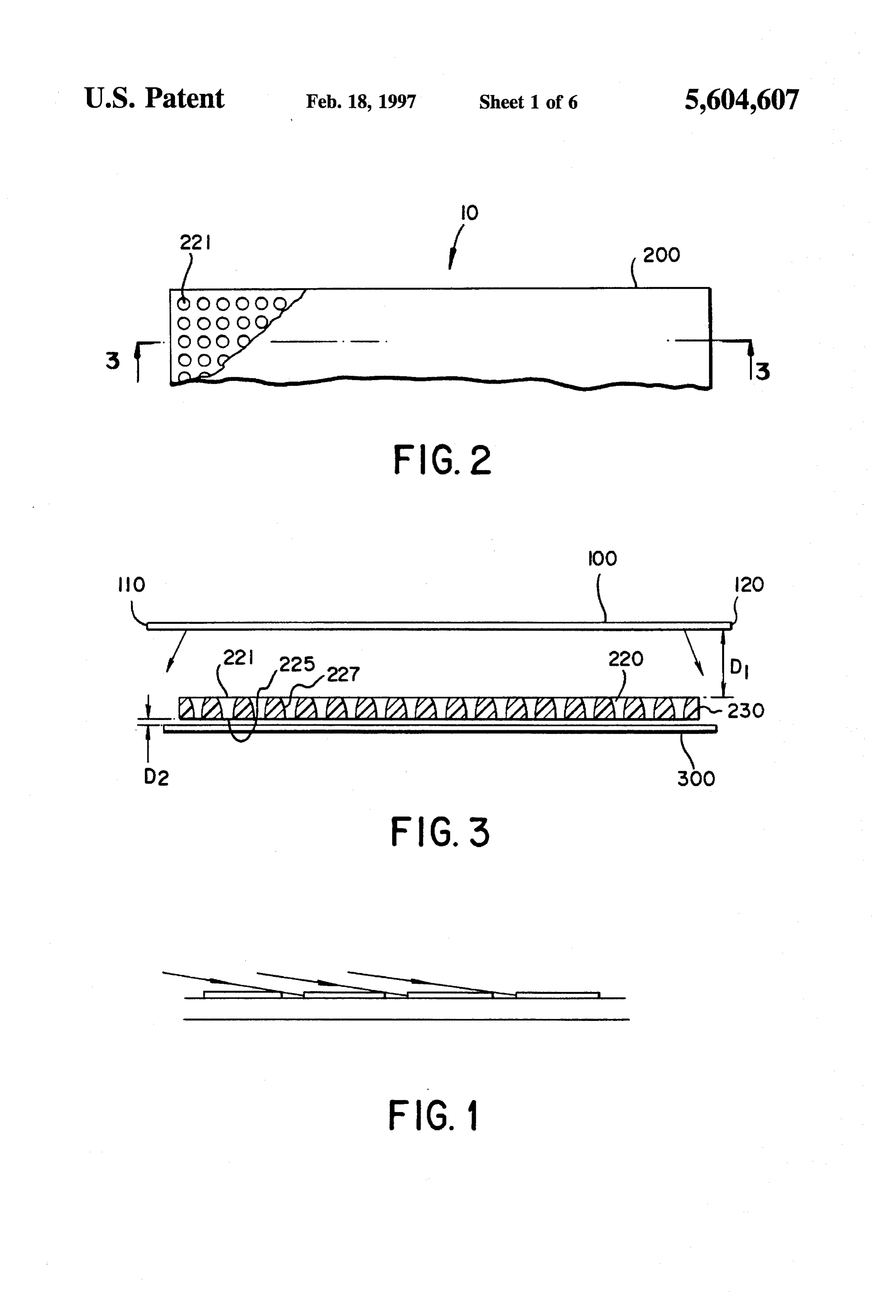
LIGHT CONCENTRATOR SYSTEM FIG. 2 schematically illustrates, greatly magnified, a
BACKGROUND OF THE INVENTION
planar view of a concentrator array of the invention.
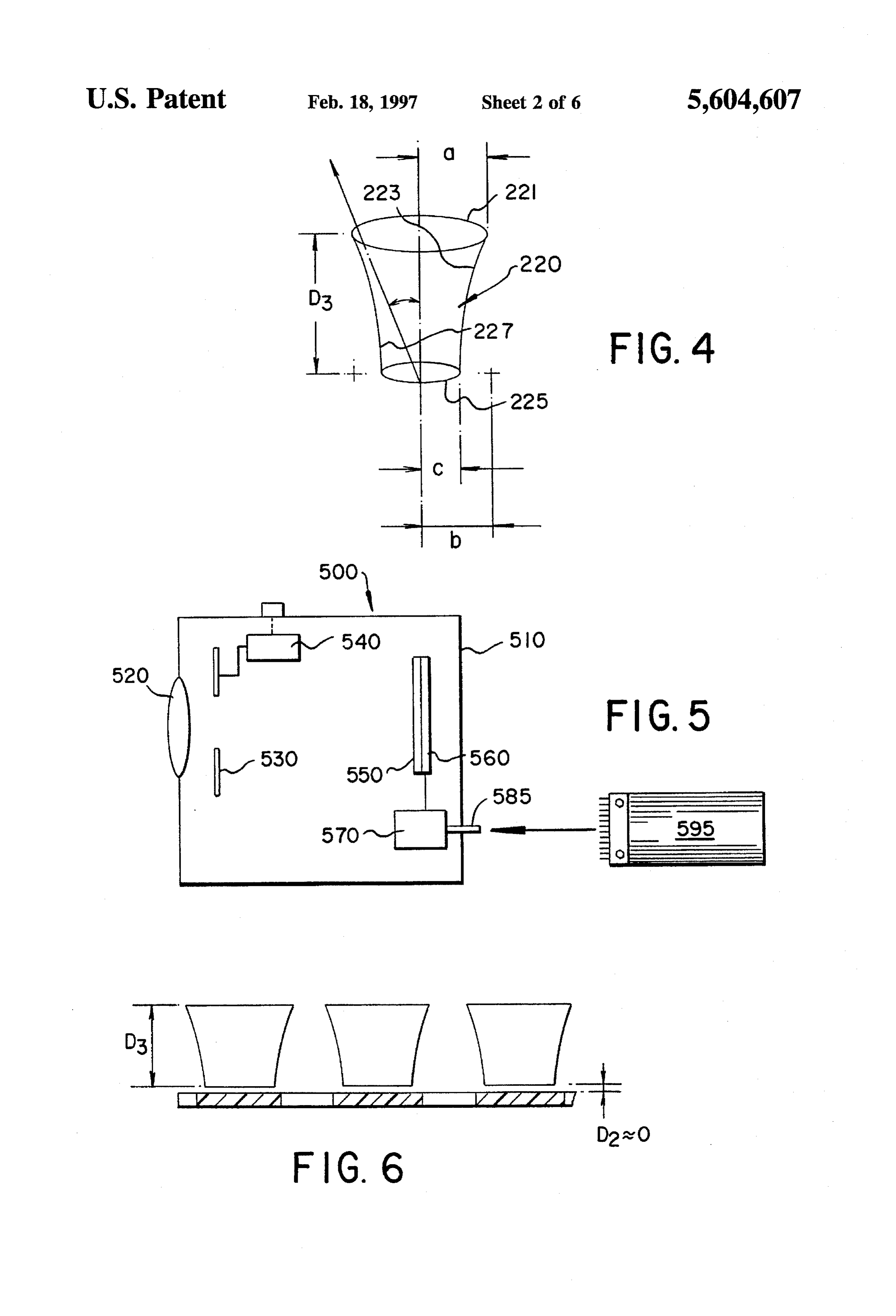
FIG. 3 illustrates an elevation section taken along line 1. Field of the Invention 3-3 of the concentrator array shown in FIG.2 and includes This invention relates to non-imaging light concentrators, a schematic of a light source and a detector array. and more particularly to concentrator arrays used in con FIG. 4 schematically illustrates in perspective a construc junction with light-sensitive mediums such as photoelec tion of an individual element of the concentrator array of tronic detector arrays or film for imaging. FIG. 2.
2. Description Relative to Prior Art 10 FIG. 5 is an elevational view in schematic of a camera that Presently, most known optical systems use lens elements incorporates a concentrator array and a CCD array in accor that image light from a source directly onto a light-sensitive dance with the invention.
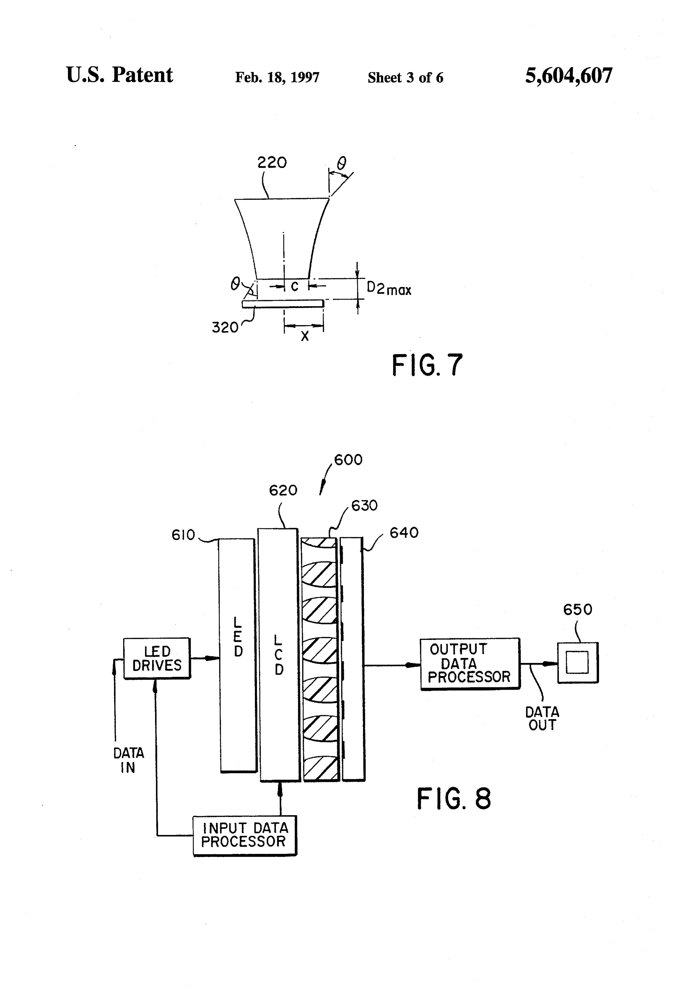
medium such as a film or a CCD array. Other known FIG. 6 is a schematic of a row of concentrator elements systems, such as one described in U.S. Pat. No. 4,975,729, located in close proximity to a detector array. employ a fiber optic bundle to channel light from a source, 15 FIG. 7 illustrates the relationship between the position of such as an LED array, onto a CCD array. the individual concentrator element of FIG. 6 and a pixel Many optical systems do not attain the optimum possible recording portion of a detector array.
signal-to-noise ratio either because they do not collect the FIG. 8 is a schematic of an optical computer that incor maximum amount of light from the light source, or because porates a detector array and a CCD array in accordance with the light leaks from one pixel to another. As will be 20 the invention.
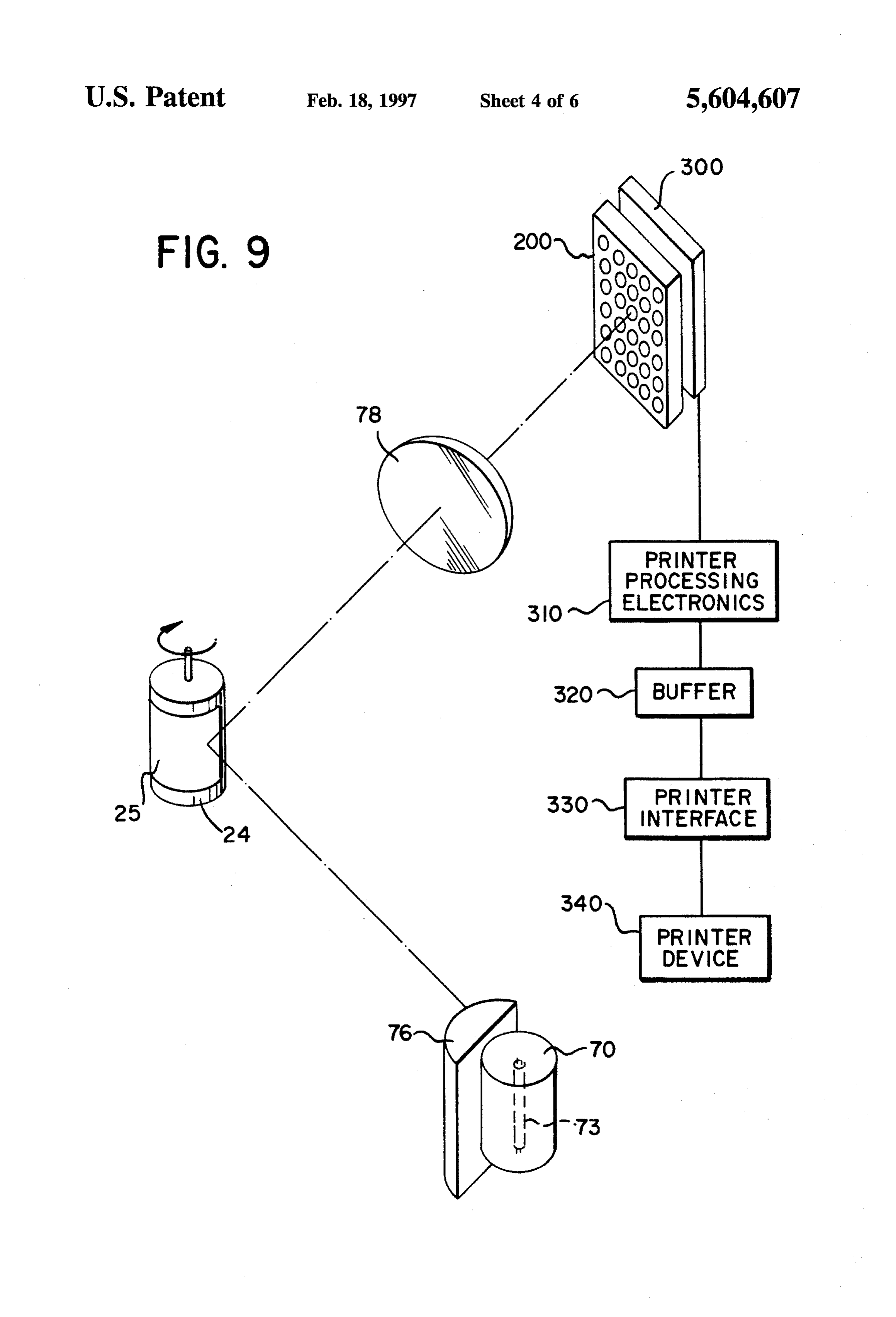
described in further detail below, photoelectronic detector FIG. 9 shows a schematic representation of an optical arrays such as charge-coupled devices (CCD's) are typically system that utilizes the invention illustrated in FIG. 1 for the made with an intercell barrier between the adjacent cells (or use in an electronic printer.
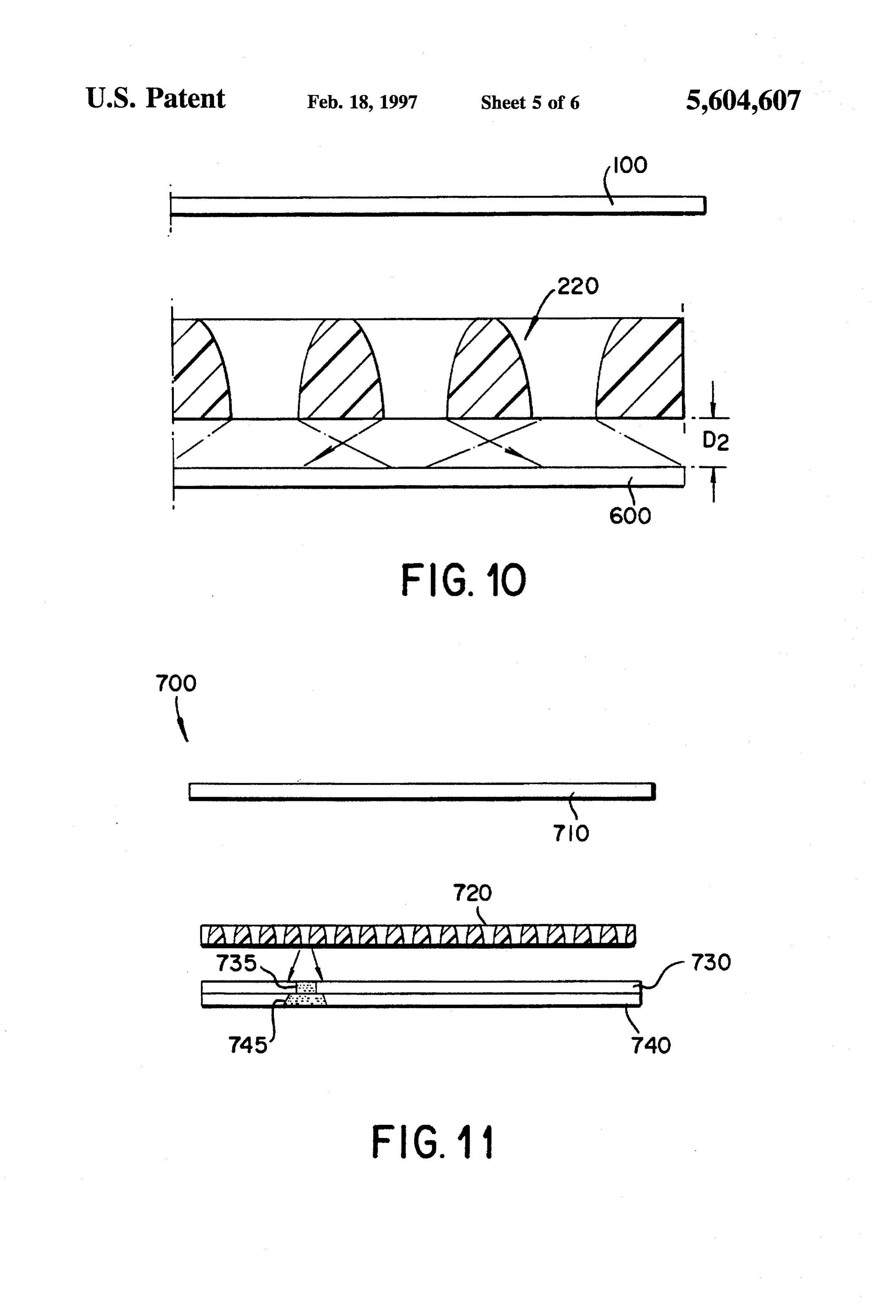
pixel recording elements). FIG. 1 shows that this barrier can FIG. 10 shows the location of the concentrator array of the be compromised by highly angular light (relative to the array 25 invention relative to a photosensitive film. normal) impinging on cell walls thereby providing inaccu rate recording. FIG. 11 shows a schematic representation of a contact printer that incorporates a concentrator array of the inven
SUMMARY OF THE INVENTION tion and a photosensitive film.
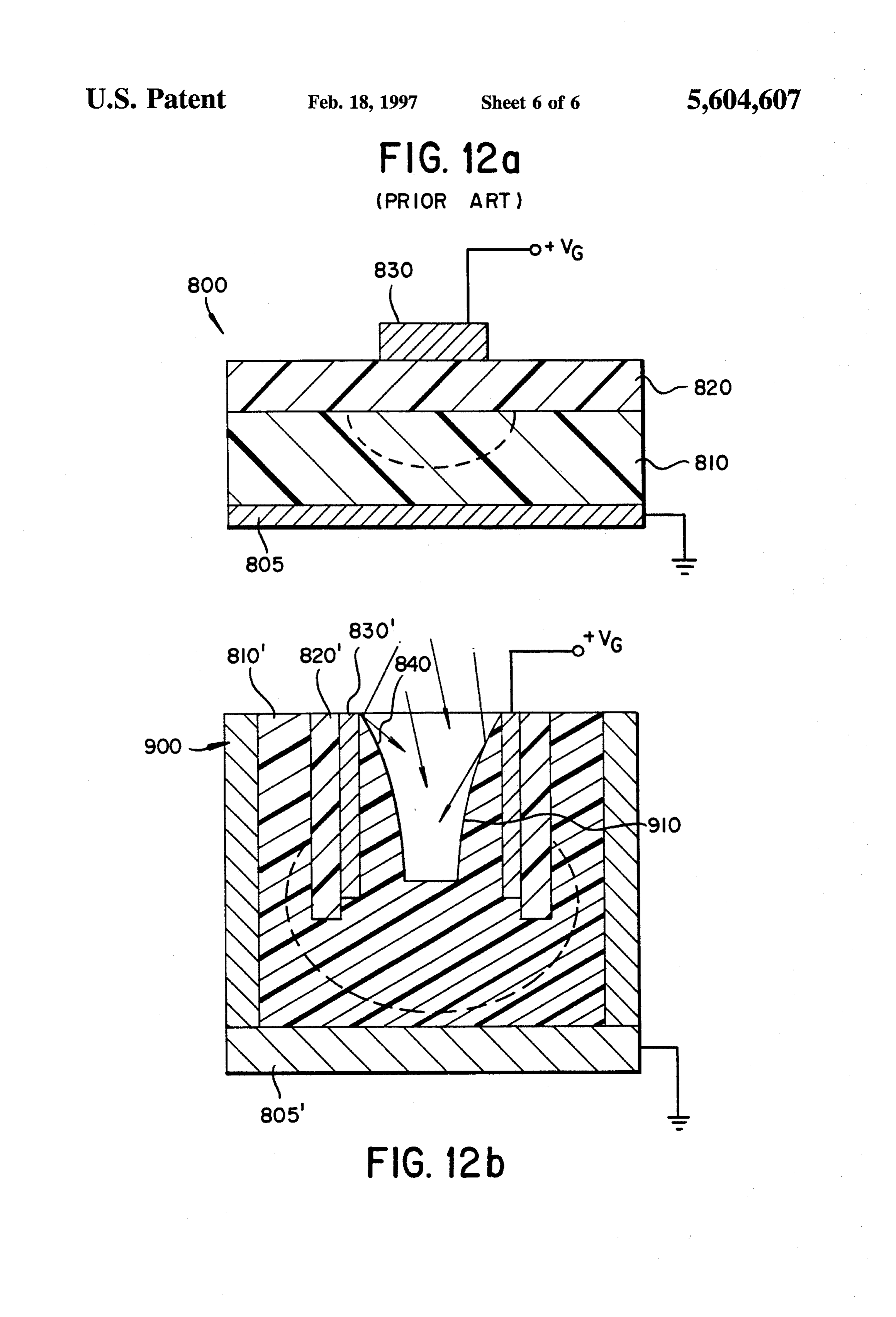
An object of this invention is to obtain an increase of 30 FIG. 12a shows a schematic representation of a CCD cell irradiance on a small area, such as pixel elements on a architecture of the prior art.
detector array and thus an increase in signal to noise ratio in FIG. 12b shows a schematic representation of a modified an optical system. Still further objects and advantages are CCD cell architecture including an embedded collector realized and will become apparent after a reading of the element in accordance with the invention.
detailed description of the embodiments of the invention. 35 DETALED DESCRIPTIONS OF THE According to the present invention, an image capture PREFERRED EMBODIMENTS system of exceptional efficiency is provided for the collec tion and concentration of electromagnetic energy. In accor Referring to FIGS. 2 and 3, them is shown a schematic of dance with the invention, there is provided a photosensitive an electromagnetic energy concentration and collection medium for capturing an image and a planar array located device 10 of one embodiment of this invention. (The details proximate to the photosensitive medium for guiding into the not shown are selectable from those known in the prior art.) medium light modulated with image information. The array The collection device 10 includes a collector or a concen includes a plurality of concentrator elements (cells) formed trator array 200 and a detector array 300. The function of a in the array. The concentrator elements each have an input 45 concentrator array (i.e. collector) 200 is to concentrate light and output opening and reflective inner wall between each coming from an image bearing source or object 100. This input and output openings. The reflective inner walls func light impinges on the collector 200 and gets funneled tion to guide and concentrate radiant energy or light imping through a plurality of concentrator elements and out of the ing upon an input opening toward and through a output (exit) collector array onto the surface of the detector array 300. opening toward the photosensitive medium. According to 50 The array 300 is typically an area array sensor such as a one aspect of the invention, the photosensitive medium is CCD (charge coupled device). The source or object is film. According to another aspect of the invention, the typically of one- or two-dimensional form and of finite photosensitive medium is a detector array. It is contemplated dimensions defined in one dimension by edges 110 and 120 that the detector array will have a plurality of pixel elements and is of finite distance D from the concentrator array 200. for detection of the above-mentioned radiant energy. In a 55 This collector 200 includes a plurality of reflective, posi preferred embodiment of the structure of the present inven tively curved (with respect to the incident light), non tion a detector array and a collector (i.e. a concentrator imaging concentrator elements 220 illustrated in FIG.3. The array) are located in close proximity with one another and concentrator elements are specially shaped pathways or are aligned in such a way, that the centers of the above conduits formed in the opaque material 230. An individual mentioned exit opening of concentrator elements will cor 60 concentrator element 220 is illustrated in FIG. 4. Each respond closely to the centers of the above-mentioned pixel concentrator element has an input opening 221 and an output elements. opening (i.e. an exit opening) 225. These openings are BRIEF DESCRIPTION OF THE DRAWINGS typically circular in shape, although other shape openings can also be used. There is a reflective inner wall 227 between
FIG. 1 is an enlarged schematic elevational view of a 65 each input and output opening. The concentrator elements portion of a CCD array and illustrating highly angular light have hyperbolic inner walls and are typically hollow inside rays impinging on pixel recording elements thereof. (i.e. have air as medium). However, it is contemplated that
Page 9
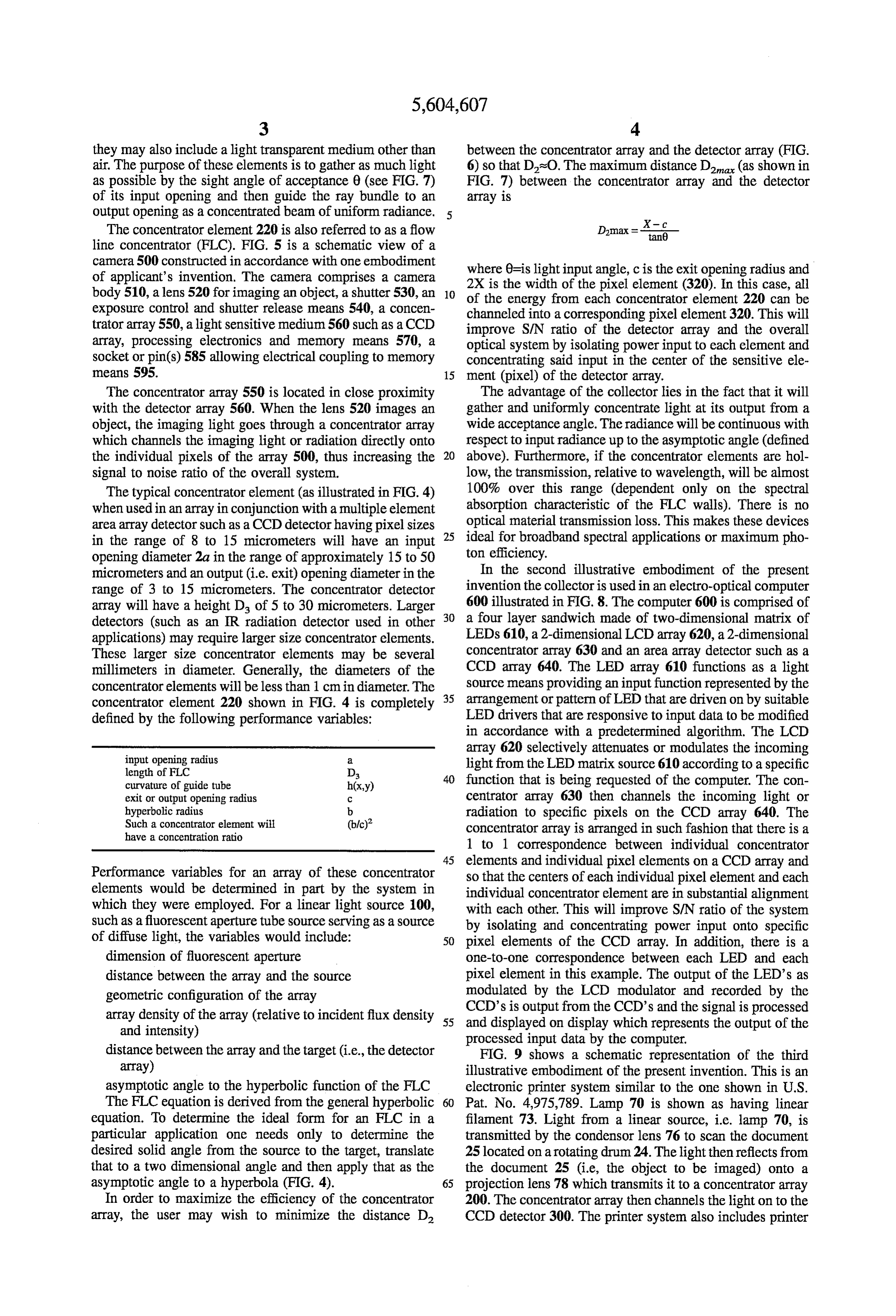
they may also include a light transparent medium other than between the concentrator array and the detector array (FIG. air. The purpose of these elements is to gather as much light 6) so that Dis0. The maximum distance D (as shown in as possible by the sight angle of acceptance 0 (see FIG. 7) FIG. 7) between the concentrator array and the detector of its input opening and then guide the ray bundle to an array is output opening as a concentrated beam of uniform radiance. X- C The concentrator element 220 is also referred to as a flow Damax = tan line concentrator (FLC). FIG. 5 is a schematic view of a camera 500 constructed in accordance with one embodiment of applicant's invention. The camera comprises a camera where 0=is light input angle, c is the exit opening radius and 2X is the width of the pixel element (320). In this case, all body 510, a lens 520 for imaging an object, a shutter 530, an 10 of the exposure control and shutter release means 540, a concen energy from each concentrator element 220 can be trator array550, a light sensitive medium 560 such as a CCD channeled into a corresponding pixel element 320. This will improve S/N ratio of the detector array and the overall array, processing electronics and memory means 570, a optical system by isolating power input to each element and socket or pin(s) 585 allowing electrical coupling to memory concentrating said input in the center of the sensitive ele means 595. 15 ment (pixel) of the detector array. The concentrator array 550 is located in close proximity The advantage of the collector lies in the fact that it will with the detector array 560. When the lens 520 images an gather and uniformly concentrate light at its output from a object, the imaging light goes through a concentrator array wide acceptance angle. The radiance will be continuous with which channels the imaging light or radiation directly onto respect to input radiance up to the asymptotic angle (defined the individual pixels of the array 500, thus increasing the 20 above). Furthermore, if the concentrator elements are hol signal to noise ratio of the overall system. low, the transmission, relative to wavelength, will be almost The typical concentrator element (as illustrated in FIG. 4) 100% over this range (dependent only on the spectral when used in an array in conjunction with a multiple element absorption characteristic of the FLC walls). There is no area array detector such as a CCD detector having pixel sizes 25 optical material transmission loss. This makes these devices in the range of 8 to 15 micrometers will have an input ton ideal for broadband spectral applications or maximum pho opening diameter 2a in the range of approximately 15 to 50 efficiency.
micrometers and an output (i.e. exit) opening diameter in the In the second illustrative embodiment of the present range of 3 to 15 micrometers. The concentrator detector invention the collector is used in an electro-optical computer array will have a height D. of 5 to 30 micrometers. Larger 600 illustrated in FIG.8. The computer 600 is comprised of detectors (such as an IR radiation detector used in other 30 a four layer sandwich made of two-dimensional matrix of applications) may require larger size concentrator elements. LEDs 610, a 2-dimensional LCD array 620, a 2-dimensional These larger size concentrator elements may be several concentrator array 630 and an area array detector such as a millimeters in diameter. Generally, the diameters of the CCD array 640. The LED array 610 functions as a light concentrator elements will be less than 1 cm in diameter. The source means providing an input function represented by the concentrator element 220 shown in FIG. 4 is completely 35 arrangement or pattern of LED that are driven on by suitable defined by the following performance variables: LED drivers that are responsive to input data to be modified in accordance with a predetermined algorithm. The LCD
array 620 selectively attenuates or modulates the incoming length of FLC D light from the LED matrix source 610 according to a specific curvature of guide tube h(x,y) function that is being requested of the computer. The con exit or output opening radius C centrator array 630 then channels the incoming light or hyperbolic radius b radiation to specific pixels on the CCD array 640. The Such a concentrator element will (blic)? concentrator array is arranged in such fashion that there is a have a concentration ratio 1 to 1 correspondence between individual concentrator 45 elements and individual pixel elements on a CCD array and
Performance variables for an array of these concentrator so that the centers of each individual pixel element and each elements would be determined in part by the system in individual concentrator element are in substantial alignment which they were employed. For a linear light source 100, with each other. This will improve S/N ratio of the system Such as a fluorescent aperture tube source serving as a source by isolating and concentrating power input onto specific of diffuse light, the variables would include: 50 pixel elements of the CCD array. In addition, there is a dimension of fluorescent aperture one-to-one correspondence between each LED and each distance between the array and the source pixel element in this example. The output of the LED's as geometric configuration of the array modulated by the LCD modulator and recorded by the array density of the array (relative to incident flux density 55 CCD's and is output from the CCD's and the signal is processed displayed on display which represents the output of the and intensity) processed input data by the computer. distance between the array and the target (i.e., the detector FIG. 9 shows a schematic representation of the third array) illustrative embodiment of the present invention. This is an asymptotic angle to the hyperbolic function of the FLC electronic printer system similar to the one shown in U.S. The FLC equation is derived from the general hyperbolic 60 Pat. No. 4,975,789. Lamp 70 is shown as having linear equation. To determine the ideal form for an FLC in a filament 73. Light from a linear source, i.e. lamp 70, is particular application one needs only to determine the transmitted by the condensor lens 76 to scan the document desired solid angle from the source to the target, translate 25 located on a rotating drum 24. The light then reflects from that to a two dimensional angle and then apply that as the the document 25 (i.e., the object to be imaged) onto a asymptotic angle to a hyperbola (FIG. 4). 65 projection lens 78 which transmits it to a concentrator array In order to maximize the efficiency of the concentrator 200. The concentrator array then channels the light on to the array, the user may wish to minimize the distance D CCD detector 300. The printer system also includes printer
Page 10
processing electronics 310, a buffer 320, a printer interface Glass blown concentrator elements may prove cost effec 330 and a printer device 340 for reproducing the information tive in large, uniform quantities. In this method, a glass tube on the original document. Again, as the scanning function is of desired length and wall thickness is heated and subjected formed, the light from the object is being channeled into the to gas pressure at one end. The pressure, combined with the concentrator array 200 and then onto the detector 300. 5 softened glass, will form the desired input aperture shape at The fourth illustrative embodiment of the present inven the tube end. These methods can be used to approach the tion is the film exposure apparatus (FIG. 10) the object of theoretical dimensions of a FLC. In the array form, slight which is to uniformly expose a section of the film roll for errors would be lost in the average. testing purposes. In this embodiment, the collector array is The array configuration of concentrator elements as non used to provide a uniform illumination in the image plane 10 imaging number elements in an optical train could be applied to a of systems to increase efficiency. One primary where a light-sensitive medium (i.e. film 600) is located.
Note that the distance D between the collector array and the possibility is the use in front of multi-element, solid state, photosensitive devices (e.g., CCD array). An example of light-sensitive medium is relatively large (FIG. 10), so that such use is illustrated in some of the above embodiments. the light from source 100 and collected from each of the This would have the effect of increasing the photonic concentrator elements 220 is overlapped by light collected 15 efficiency of these devices particularly when coupled with from at least one adjacent concentrator element. the proper lens system by isolating power input to each The fifth illustrative embodiment of the present invention element and concentrating said input in the center of the is the contact printer system 700 shown in FIG. 11. The sensitive element. The emphasis here is on the hyperbolic optical system of this embodiment includes a diffuse light FLC though a compound parabolic concentrator may be source 710, a concentrator array 720, a film original 730 20 more applicable under some conditions. having an image 735 to be copied onto a copy film 740. The invention has been described in detail with particular Latent image 745 is shown recorded on copy film 740 and reference to preferred embodiments thereof, but it will be this latent image is the image formed of the image 735 to be understood that variations and modifications can be effected copied. Since the output angle of the light which is leaving within the spirit and scope of the invention. the concentrator array 720 is the same as the input angle of 25 I claim:
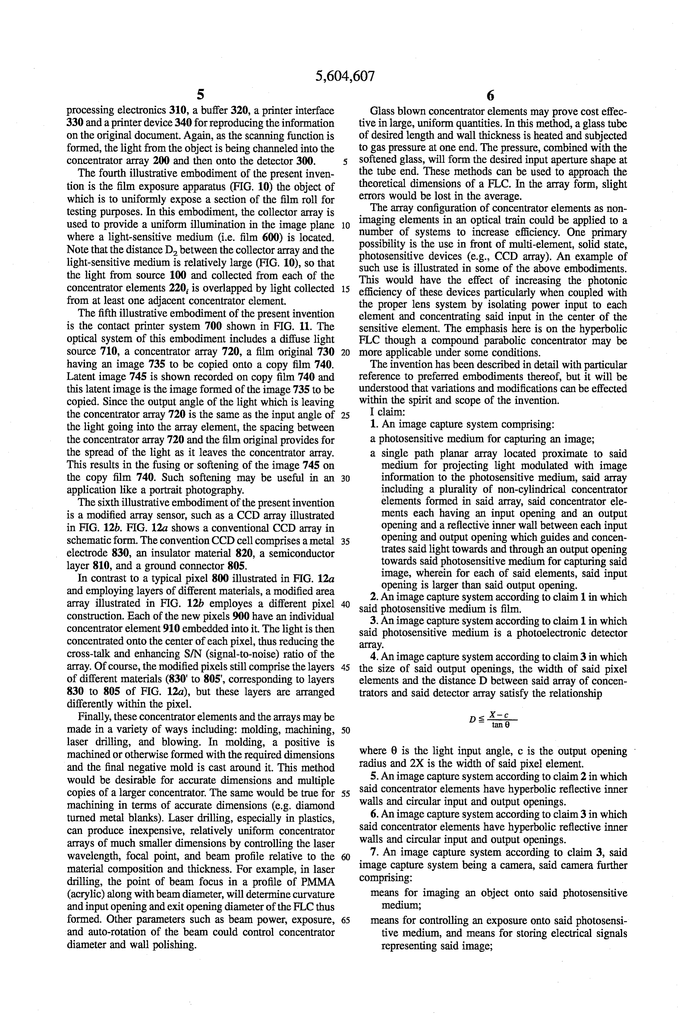
the light going into the array element, the spacing between 1. An image capture system comprising: the concentrator array720 and the film original provides for a photosensitive medium for capturing an image; the spread of the light as it leaves the concentrator array. a single path planar array located proximate to said This results in the fusing or softening of the image 745 on medium for projecting light modulated with image the copy film 740. Such softening may be useful in an 30 information to the photosensitive medium, said array application like a portrait photography. including a plurality of non-cylindrical concentrator The sixth illustrative embodiment of the present invention elements formed in said array, said concentrator ele is a modified array sensor, such as a CCD array illustrated ments each having an input opening and an output in FIG. 12b. FIG. 12a shows a conventional CCD array in opening and a reflective inner wall between each input schematic form. The convention CCD cell comprises a metal 35 opening and output opening which guides and concen electrode 830, an insulator material 820, a semiconductor trates said light towards and through an output opening layer 810, and a ground connector 805. towards said photosensitive medium for capturing said In contrast to a typical pixel 800 illustrated in FIG. 12a image, wherein for each of said elements, said input and employing layers of different materials, a modified area opening is larger than said output opening. 2. An image capture system according to claim 1 in which array illustrated in FIG. 12b employes a different pixel 40 said photosensitive construction. Each of the new pixels 900 have an individual medium is film. 3. An image capture system according to claim 1 in which concentrator element 910 embedded into it. The light is then said photosensitive medium is a photoelectronic detector concentrated onto the center of each pixel, thus reducing the array.
cross-talk and enhancing S/N (signal-to-noise) ratio of the 4. An image capture system according to claim3 in which array. Of course, the modified pixels still comprise the layers 45 the size of said output openings, the width of said pixel of different materials (830' to 805, corresponding to layers elements and the distance D between said array of concen 830 to 805 of FIG. 12a), but these layers are arranged trators and said detector array satisfy the relationship differently within the pixel.
Finally, these concentrator elements and the arrays may be DSs tan made in a variety of ways including: molding, machining, 50 laser drilling, and blowing. In molding, a positive is machined or otherwise formed with the required dimensions where 0 is the light input angle, c is the output opening and the final negative mold is cast around it. This method radius and 2X is the width of said pixel element. would be desirable for accurate dimensions and multiple 5. An image capture system according to claim2 in which said concentrator elements have hyperbolic reflective inner copies of a larger concentrator. The same would be true for 55 walls machining in terms of accurate dimensions (e.g. diamond and circular input and output openings. turned metal blanks). Laser drilling, especially in plastics, 6. An image capture system according to claim3 in which can produce inexpensive, relatively uniform concentrator walls said concentrator elements have hyperbolic reflective inner arrays of much smaller dimensions by controlling the laser and circular input and output openings. wavelength, focal point, and beam profile relative to the 60 7. An image capture system according to claim 3, said material composition and thickness. For example, in laser image capture system being a camera, said camera further drilling, the point of beam focus in a profile of PMMA comprising:
(acrylic) along with beam diameter, will determine curvature means for imaging an object onto said photosensitive and input opening and exit opening diameter of the FLC thus medium;
formed. Other parameters such as beam power, exposure, 65 means for controlling an exposure onto said photosensi and auto-rotation of the beam could control concentrator tive medium, and means for storing electrical signals diameter and wall polishing. representing said image;
Page 11
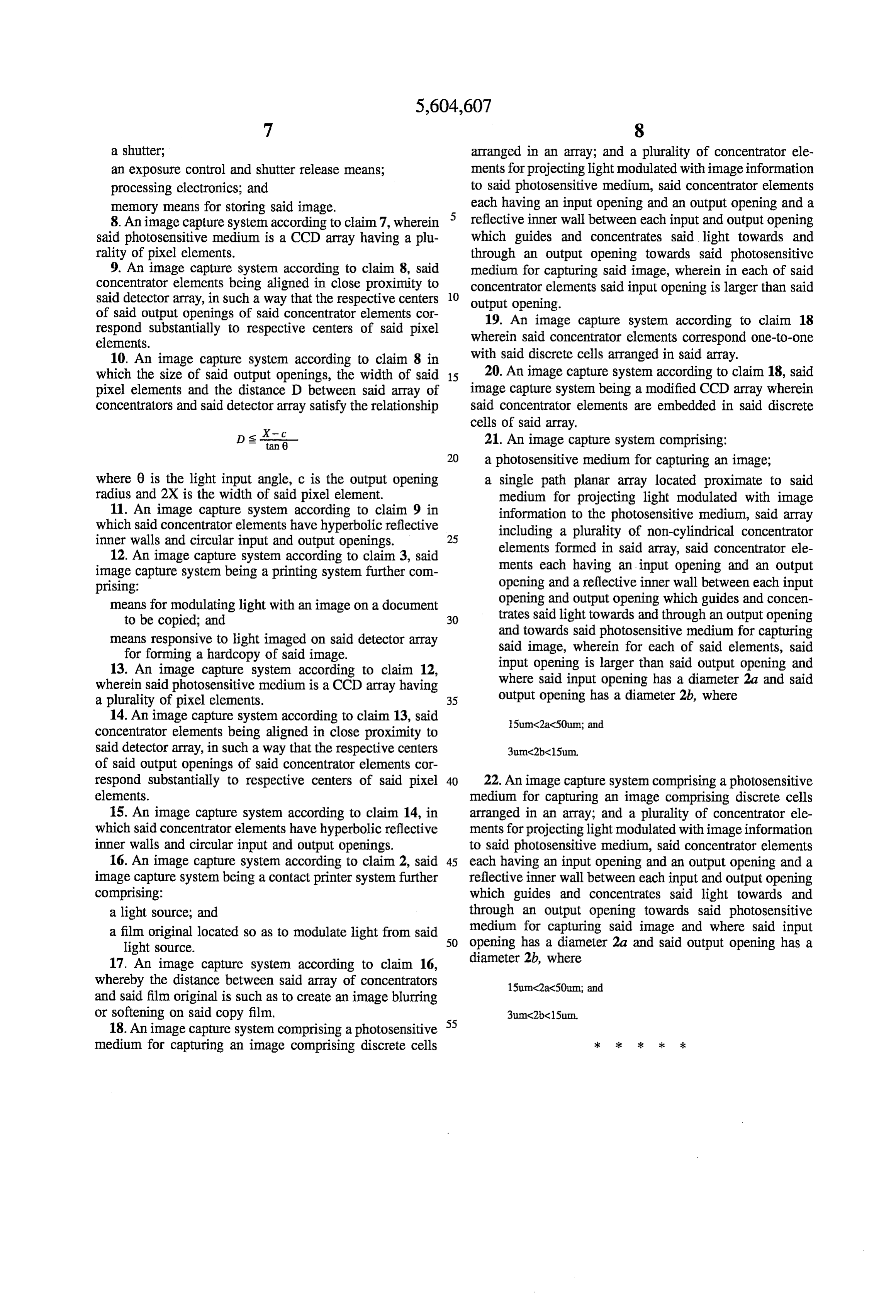
a shutter; arranged in an array; and a plurality of concentrator ele an exposure control and shutter release means; ments for projecting light modulated with image information processing electronics; and to said photosensitive medium, said concentrator elements memory means for storing said image. each having an input opening and an output opening and a 8. An image capture system according to claim 7, wherein reflective inner wall between each input and output opening said photosensitive medium is a CCD array having a plu which guides and concentrates said light towards and rality of pixel elements. through an output opening towards said photosensitive 9. An image capture system according to claim 8, said medium for capturing said image, wherein in each of said concentrator elements being aligned in close proximity to concentrator elements said input opening is larger than said said detector array, in such a way that the respective centers 10 output opening.
of said output openings of said concentrator elements cor 19. An image capture system according to claim 18 respond substantially to respective centers of said pixel elements. wherein said concentrator elements correspond one-to-one 10. An image capture system according to claim 8 in with said discrete cells arranged in said array. which the size of said output openings, the width of said 15 20. An image capture system according to claim 18, said pixel elements and the distance D between said array of image capture system being a modified CCD array wherein concentrators and said detector array satisfy the relationship said concentrator elements are embedded in said discrete cells of said array.
s X-C 21. An image capture system comprising:
Ds tan 6 20 a photosensitive medium for capturing an image;
where 0 is the light input angle, c is the output opening a single path planar array located proximate to said radius and 2X is the width of said pixel element. medium for projecting light modulated with image 11. An image capture system according to claim 9 in information to the photosensitive medium, said array which said concentrator elements have hyperbolic reflective including a plurality of non-cylindrical concentrator inner walls and circular input and output openings. elements formed in said array, said concentrator ele 12. An image capture system according to claim 3, said ments each having an input opening and an output image capture system being a printing system further com prising: opening and a reflective inner wall between each input means for modulating light with an image on a document opening and output opening which guides and concen to be copied; and 30 trates said light towards and through an output opening means responsive to light imaged on said detector array and towards said photosensitive medium for capturing for forming a hardcopy of said image. said image, wherein for each of said elements, said 13. An image capture system according to claim 12, input opening is larger than said output opening and wherein said photosensitive medium is a CCD array having where said input opening has a diameter 2a and said a plurality of pixel elements. 35 output opening has a diameter 2b, where 14. An image capture system according to claim 13, said 15umC2a350um; and concentrator elements being aligned in close proximity to said detector array, in such a way that the respective centers of said output openings of said concentrator elements cor respond substantially to respective centers of said pixel 22. An image capture system comprising a photosensitive elements. medium for capturing an image comprising discrete cells 15. An image capture system according to claim 14, in arranged in an array; and a plurality of concentrator ele which said concentrator elements have hyperbolic reflective ments for projecting light modulated with image information inner walls and circular input and output openings. to said photosensitive medium, said concentrator elements 16. An image capture system according to claim 2, said 45 each having an input opening and an output opening and a image capture system being a contact printer system further reflective inner wall between each input and output opening comprising: which guides and concentrates said light towards and a light source; and through an output opening towards said photosensitive medium for capturing said image and where said input a film original located so as to modulate light from said 50 opening light source. has a diameter 2a and said output opening has a 17. An image capture system according to claim 16, diameter 2b, where whereby the distance between said array of concentrators 15umC2aC50um; and and said film original is such as to create an image blurring or softening on said copy film.
18. An image capture system comprising a photosensitive 55 medium for capturing an image comprising discrete cells
Provenance
- Collection
- Patents citing this work
- Current assignee
- Omnivision Technologies Inc
- Original assignee
- Eastman Kodak Co
- Pages
- 11
- Method
- pdftotext (the PDF's own text layer) + pdftoppm 300dpi page scans
- Patent office record
- patents.google.com →
- Source
- Google Patents citing-documents table
- Inventors
- Alexander D. Mirzaoff; Eastman Kodak Co
- Published
- 1997-02-18
- Transcribed from
- patentimages.storage.googleapis.com →