patent · US4441783
Vessel navigation lights
10 April 1984
Page 1 — bibliographic record
4. A CA 84 C r 4 44 78 i,
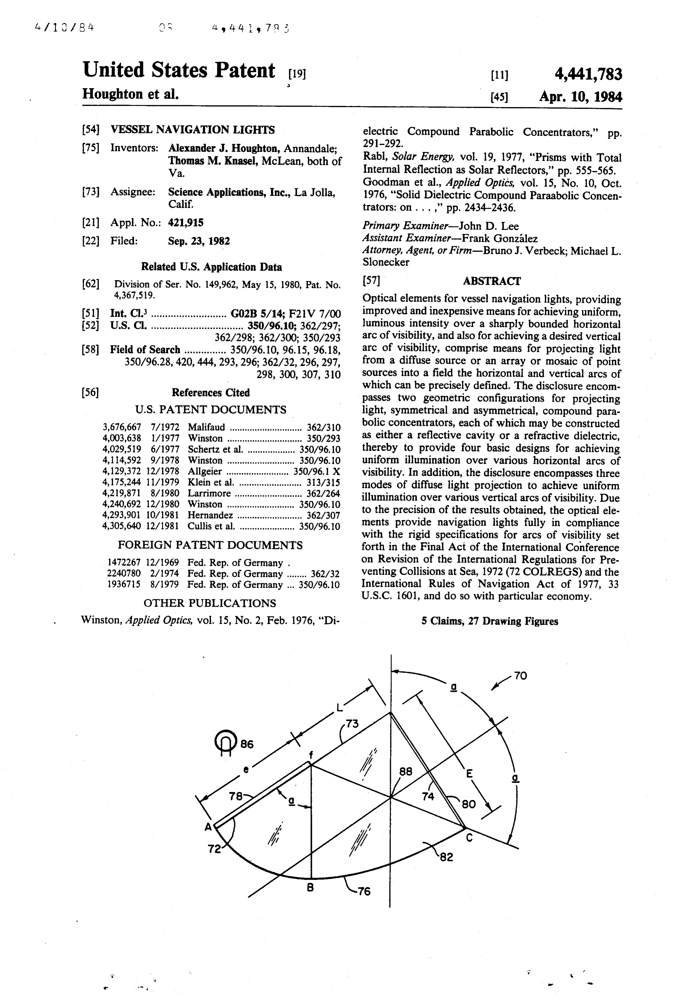
United States Patent (19) (11) 4,441,783 Houghton et al. (45) Apr. 10, 1984 54 VESSEL NAVIGATION LIGHTS electric Compound Parabolic Concentrators," pp. 75) Inventors: Alexander J. Houghton, Annandale; 291-292.
Thomas M. Knasel, McLean, both of Rabl, Solar Energy, vol. 19, 1977, "Prisms with Total Va. Internal Reflection as Solar Reflectors," pp. 555-565. Goodman et al., Applied Optics, vol. 15, No. 10, Oct.
73 Assignee: Science Applications, Inc., La Jolla, 1976, "Solid Dielectric Compound Paraabolic Concen Calif. trators: on ...,’ pp. 2434-2436.
(21) Appl. No.: 421,915 Primary Examiner-John D. Lee (22 Filed: Sep. 23, 1982 Assistant Examiner-Frank Gonzalez Attorney, Agent, or Firm-Bruno J. Verbeck; Michael L.
Related U.S. Application Data Slonecker 62) Division of Ser. No. 149,962, May 15, 1980, Pat. No. 57 ABSTRACT 4,367,519. Optical elements for vessel navigation lights, providing 51 Int, Cl............................ GO2B 5/14; F21V 7/00 improved and inexpensive means for achieving uniform, 52 U.S. C. ................................. 350/96.10; 362/297; luminous intensity over a sharply bounded horizontal 362/298; 362/300; 350/293 arc of visibility, and also for achieving a desired vertical 58 Field of Search ............... 350/96.10, 96.15, 96.18, arc of visibility, comprise means for projecting light 350/96.28,420, 444, 293,296; 362/32,296,297, from a diffuse source or an array or mosaic of point 298, 300, 307, 310 sources into a field the horizontal and vertical arcs of (56) References Cited which can be precisely defined. The disclosure encom passes two geometric configurations for projecting
3,676,667, 7/1972 Malifaud ............................. 362/310 bolic concentrators, each of which may be constructed 4,003,638 1/1977 Winston .............................. 350/293 as either a reflective cavity or a refractive dielectric, 4,029,519 6/1977 Schertz et al. ................... 350/96.10 thereby to provide four basic designs for achieving 4,114,592 9/1978 Winston ........................... 350/96.10 uniform illumination over various horizontal arcs of 4,129,372 12/1978 Allgeier ......................... 350/96.1 X visibility. In addition, the disclosure encompasses three 4, 175,244 11/1979 Klein et al. ..... ... 313/315 modes of diffuse light projection to achieve uniform 4,219,871 8/1980 Larrimore ... ... 362/264 illumination over various vertical arcs of visibility. Due 4,240,692 12/1980 Winston ...... 350/96.10 to the precision of the results obtained, the optical ele 4,293,901 10/1981 Hernandez .......................... 362/307 4,305,640 12/1981 Cullis et al. ...................... 350/96.10 ments provide navigation lights fully in compliance
FOREIGN PATENT DOCUMENTS
with the rigid specifications for arcs of visibility set forth in the Final Act of the International Conference 1472267 12/1969 Fed. Rep. of Germany . on Revision of the International Regulations for Pre 2240780 2/1974 Fed. Rep. of Germany ........ 362/32 venting Collisions at Sea, 1972 (72 COLREGS) and the 1936715 8/1979 Fed. Rep. of Germany ... 350/96.10 International Rules of Navigation Act of 1977, 33
OTHER PUBLICATIONS
U.S.C. 1601, and do so with particular economy.
Winston, Applied Optics, vol. 15, No. 2, Feb. 1976, "Di 5 Claims, 27 Drawing Figures
Page 2
Drawing sheet — no readable text.
Page 3
Drawing sheet — no readable text.
Page 4
Drawing sheet — no readable text.
Page 5
Drawing sheet — no readable text.
Page 6
Drawing sheet — no readable text.
Page 7
Drawing sheet — no readable text.
Page 8
Drawing sheet — no readable text.
Page 9
Drawing sheet — no readable text.
Page 10
source, the distance from the source to the screen, and
WESSEL NAVIGATION LIGHTS the length of the screen. Since the light source has finite
CROSS REFERENCE
size, achievement of a sharp cutoff is not possible. Very long screens, on the order of several feet, are satisfac
This application is a division of application Ser. No. 5 tory for meeting legal definitions of "proper lights,' 149,962, filed May 15, 1980, now U.S. Pat. No. but are not suitable for small vessels. On small vessels, 4,367,519, screens, if they are used at all, are too short to be effec The subject matter of this application is disclosed in tive. Consequently, small vessel lights have tradition Disclosure Document No. 076259, filed Dec. 4, 1978, O ally had only vaguely defined arcs and ranges of visibil
BACKGROUND OF THE INVENTION The 1972 International Regulations, 72 COLREGS, The importance of proper running and riding lights have now established precise requirements for naviga on vessels using public navigable waters cannot be over 15 of visibilitywith tion lights respect to (a) range of visibility, (b) arcs emphasized. During the hours of darkness, it is the difficult design (c) and chromaticity. The net result is a very requirement for small vessel lights.
function of these lights in clear weather to give such The U.S. boating industry has vigorously opposed timely and effective notice to one vessel of the proxim ratification of the 72 COLREGS on the basis that con ity of another that all doubt as to her character and intentions will be satisfactorily settled before there is pliance by small boats is technically and economically any serious risk of collision. Even in thick fog, with the 20 infeasible. Nevertheless, Congress passed the Interna mariners' safety in an approaching situation dependent tional Rules of Navigation Act of 1977 (33 U.S.C. 1601) upon sound rather than upon sight, it is often the glim which, among other things, provides civil penalties mer of these same lights through the haze that finally against operators of vessels not in compliance with the enables each fog enshrouded vessel safely to feel her 72 COLREGS. In compliance with the Act, the U.S. way past the other. The definitions for proper lights are 25 Coast Guard has promulgated proposed rules for navi set forth in the Final Act of the International Confer gation lights for vessels under 20 meters in length (Fed ence on Revision of the International Regulations for eral Register, Sept. 7, 1978), which provide for testing Preventing Collisions at Sea, 1972, (72 COLREGS), the and certification of navigation lights, and require that International Rules of Navigation Act of 1977 (33
U.S.C. 1601), and the Inland Rules. It is significant that 30 lights installed after Aug. 1, 1981 have USCG certifica tion.
16 of the 38 International Rules and 16 of the 32 Inland Several foreign manufacturers have produced lights Rules relate wholely or in part to lights. In cases of which purport to meet the 72 COLREGS. These lights collision, the courts are as certain to hold a vessel at use high fault for improper lights as for a violation of signal large, and intensity point or line filaments, are rather requirements or for failure to maintain a proper lookout. 35 operation. In these lights,both are expensive, in initial cost and cost of the typical lamp consumes 25
It is evident from the case law that mere volume of light, even for a vessel at anchor on a clear night, does watts (2 amperes per lamp in a 12 volt system). As a not constitute the due notice to which approaching consequence, the burning of port, starboard and stern vessels are entitled or satisfy the requirement for regula lights for 12 hours will draw 72 ampere hours from the tion of lights. 40 vessel battery. This is an intolerable battery drain for a The importance of having lights conform to the spe sailboat and would typically require two hours of en cific regulations has been brought out in a number of gine time per day to restore the battery. cases in which incorrect lights, though visible, proved The increase in wattage is due to the requirement for misleading to approaching vessels. Strict compliance increased visibility. High power is needed because the with the regulations is thus required. 45 point or line source and screen geometry provide no By way of example, the regulations for starboard side optical gain. In an effort to achieve relatively small lights as set forth in Article 2, International Rules, read cutoff angles of visibility, only the light radiating di as follows: rectly from the filament is used, giving an optical gain of unity. Also, high power is required due to the chro
"On the starboard side a green light so constructed as SO maticity specifications which require more narrow band to show an unbroken light over an arc of the hori zon of 112 degrees (10 points of the compass) so pass the regions in the filters for colored lights. Also, due to power requirements, lamp service life is rather fixed as to throw the light from right ahead to 22 short, and lamp replacement costs are high. degrees (2 points) abaft the beam on the starboard side, and of such a character as to be visible at a 55 lights, and the expenseput
Despite the efforts into the design of these new thereof, the improved lights still distance of at least 2 miles.'
do not fully comply with the 72 COLREGS because of
The regulations for side and stern lights promulgated the difficulty in mounting and/or maintaining the verti in the '72 COLREGS are in much greater detail and are cal light filament in a precise location relative to the defined in Rules 20 through 31, inclusive, and in Annex vessel and because the light source, no matter how slim, has finite size and thus (like other prior art running l, paragraphs 2 through 5 and 7 through 13.
Heretofore all known navigational lights required to lights) an inherent visibility cutoff angle of several de have horizontal arcs of visibility of less than 360, as grees which prohibits attainment of the precise angles above set forth for side lights, achieved these arcs by of visibility required by the COLREGS. the use of screens or equivalent opaque obstructions 65 It is for these reasons, among others, that the boating which blocked the light from the sectors outside of the industry has stated that it is technically and economi desired arcs of visibility. The sharpness of the limiting cally impossible for small vessels to comply with the boundaries were a function of the size of the light new regulations.
Page 11
SUMMARY OF THE INVENTION ance with the 72 COLREGS and the implementing U.S. Statute 33 U.S.C. 1601; (2) capable of being manu
An object of the present invention is to provide a factured in such small sizes as to be ideally suited to family of optical elements facilitating the manufacture small vessels without need for elongated screens; (3) far of navigational lights having precise arcs of visibility 5 less costly than prior art lights in terms of both initial and suitable for vessels of all sizes, and particularly, investments and cost of operation, especially in compar though not exclusively, for smaller vessels, as well as ison to the lights purportedly designed to comply with lights for aircraft runways. the COLREGS: and (4) powered by an inexpensive and The invention uses the optical principle of light colli readily available light source.
mation (reflection or refraction) to achieve sharp cut 10 Other objects and advantages of the invention will offs. The input to the diverger can be a diffuse light become apparent from the following detailed descrip source or an array or mosaic of individual light sources, tion taken in conjunction with the accompanying draw having sufficient luminosity to meet the minimum re lings.
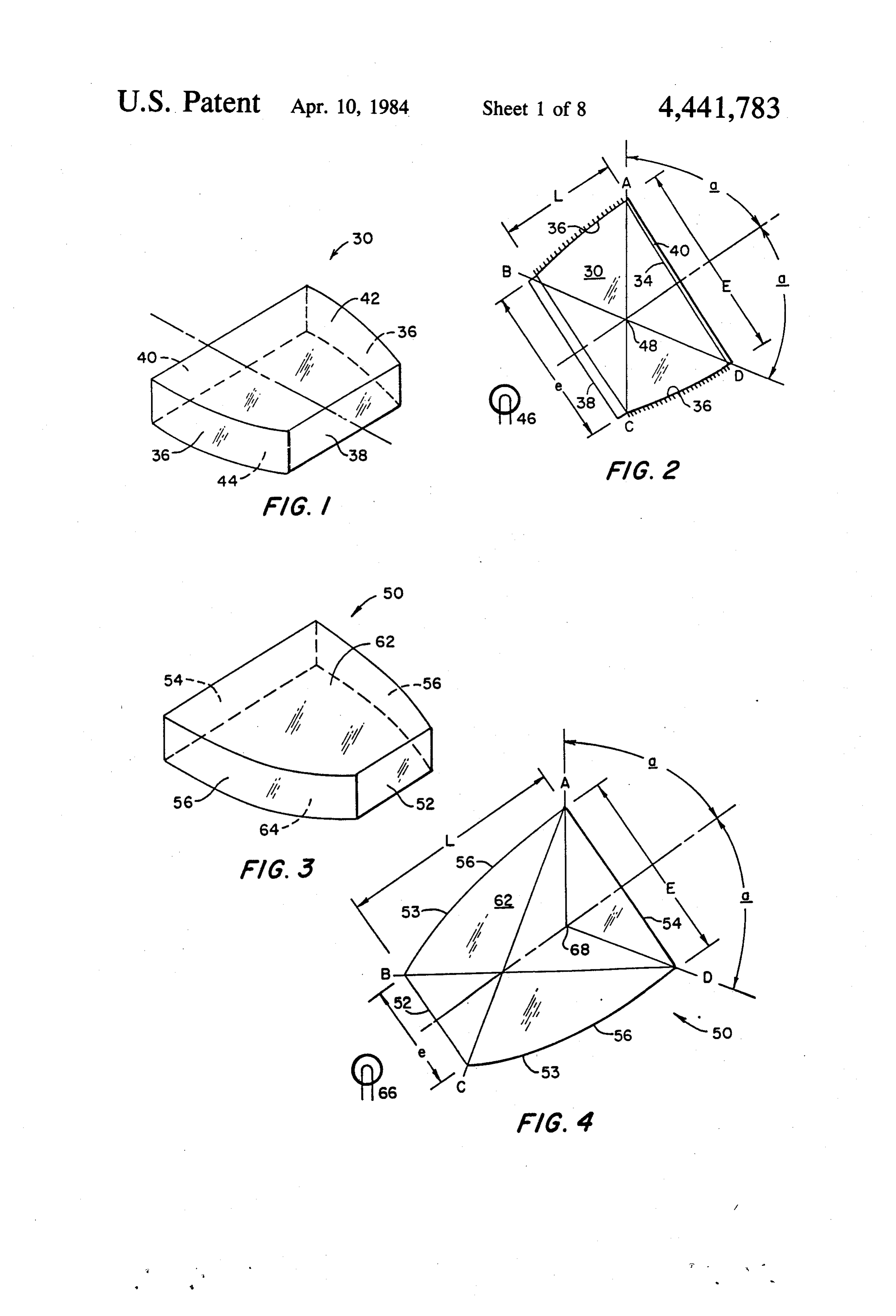
quirements for luminous intensity. Shape of the source, and the configuration of the optics will control the size 15 BRIEF DESCRIPTION OF THE DRAWINGS and shape of the illuminated field. FIG. 1 is an isometric view of one embodiment of the The invention resides in part in the design and inno optical elements of the invention in the form of a sym vative application of a family of devices originally metrical cavity diverger;
called FOCONS or ILCs (ideal light collectors) and FIG. 2 is a plan view of the embodiment of the inven now more generally referred to as CPCs (compound 20 tion shown in FIG. 1, as laid out for a starboard running parabolic concentrators). They were first described by light for a vessel;
V. K. Baranov and G. K. Melnikov (Soviet Journal of FIG. 3 is an isometric view of a second embodiment Optical TEchnology, September-October 1966) H. of the optical elements of the invention in the form of a Hintenberger and R. Winston (Review of Scientific symmetrical dielectric diverger;
Instruments, Vol. 37, No. 8, August 1966), and M. Ploke 25 FIG. 4 is a plan view of the embodiment of the inven (Lichtfuhrungseinrichtungen mit Starker Konzentra tion shown in FIG. 2, as laid out for a starboard running tionswirkung, Optik 25, Heft 1, 1969) A recent book, light for a vessel;
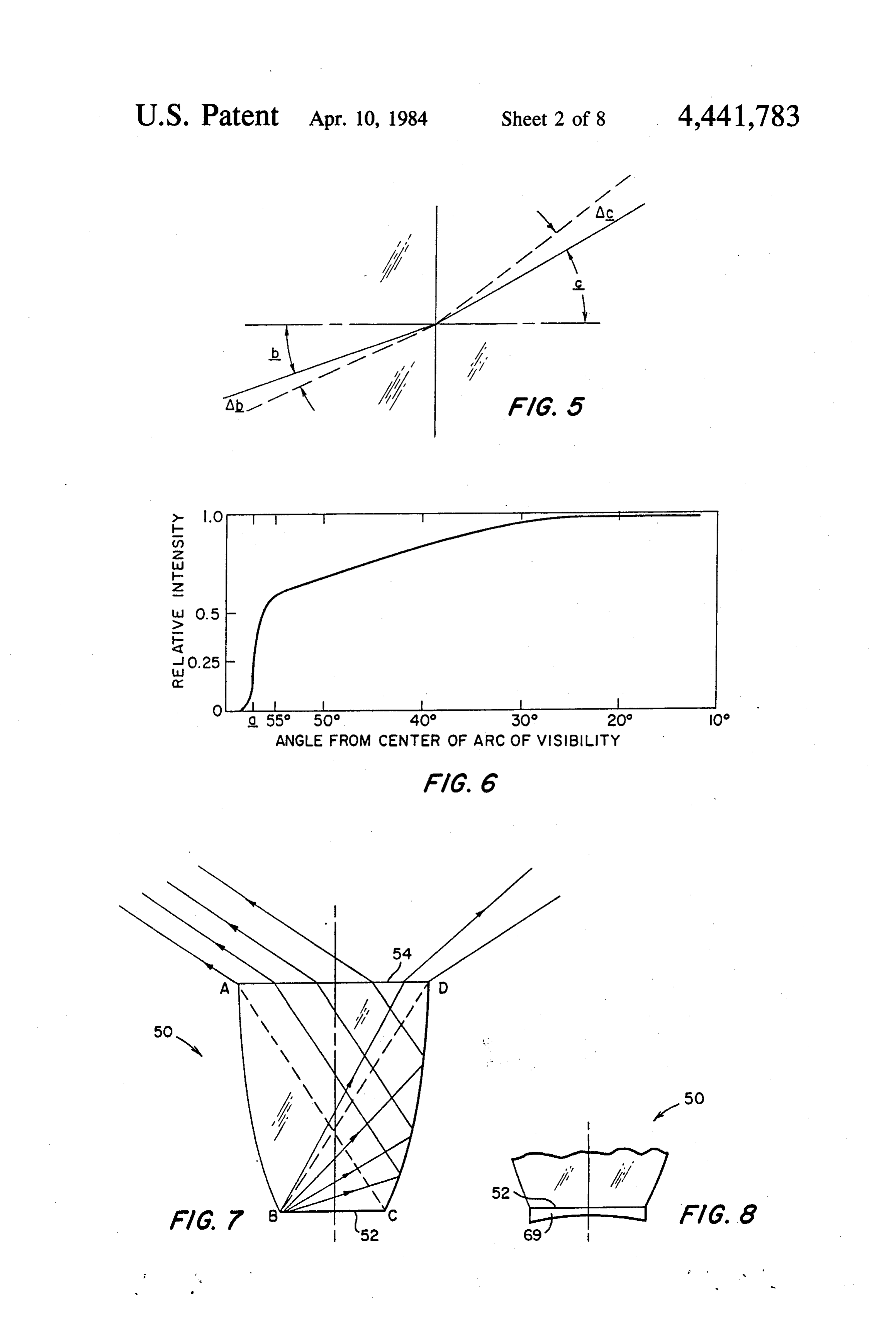
The Optics of Nonimaging Concentrators, by W. T. Wel FIG. 5 is an illustration of the refraction of light at the ford and R. Winston, Academic Press, 1978, encom exit plane of the symmetrical dielectric diverger shown pases most of the currently available technical data on 30 in FIG. 4;
the subject of CPC design. FIG. 6 is a graph illustrating the nonuniformity of the The present invention utilizes a theoretical reciprocal intensity of light at the exit plane of the dielectric di of CPC technology to achieve the particular objects of verger resulting from refraction;
the invention. Specifically, if the light exit plane of a FIG. 7 is a plan view of the symmetrical dielectric CPC is used as a light entry plane for diffuse light and 35 diverger illustrating in greater detail the mode of light the light entry plane of the CPC is used as light exit refraction at the exit plane thereof; plane, then the diffuse light introduced into the light FIG. 8 is a fragmentary plan view of a modified em entry plane (the CPC exit plane) will be projected into bodiment of the symmetrical dielectric diverger of a field accurately defined by the light source and the FIGS. 3 and 4 embodying one means for achieving CPC geometry. The inverted CPC thus becomes a pre greater uniformity of light intensity at the exit plane cision diverger for the angular projection of light. thereof;
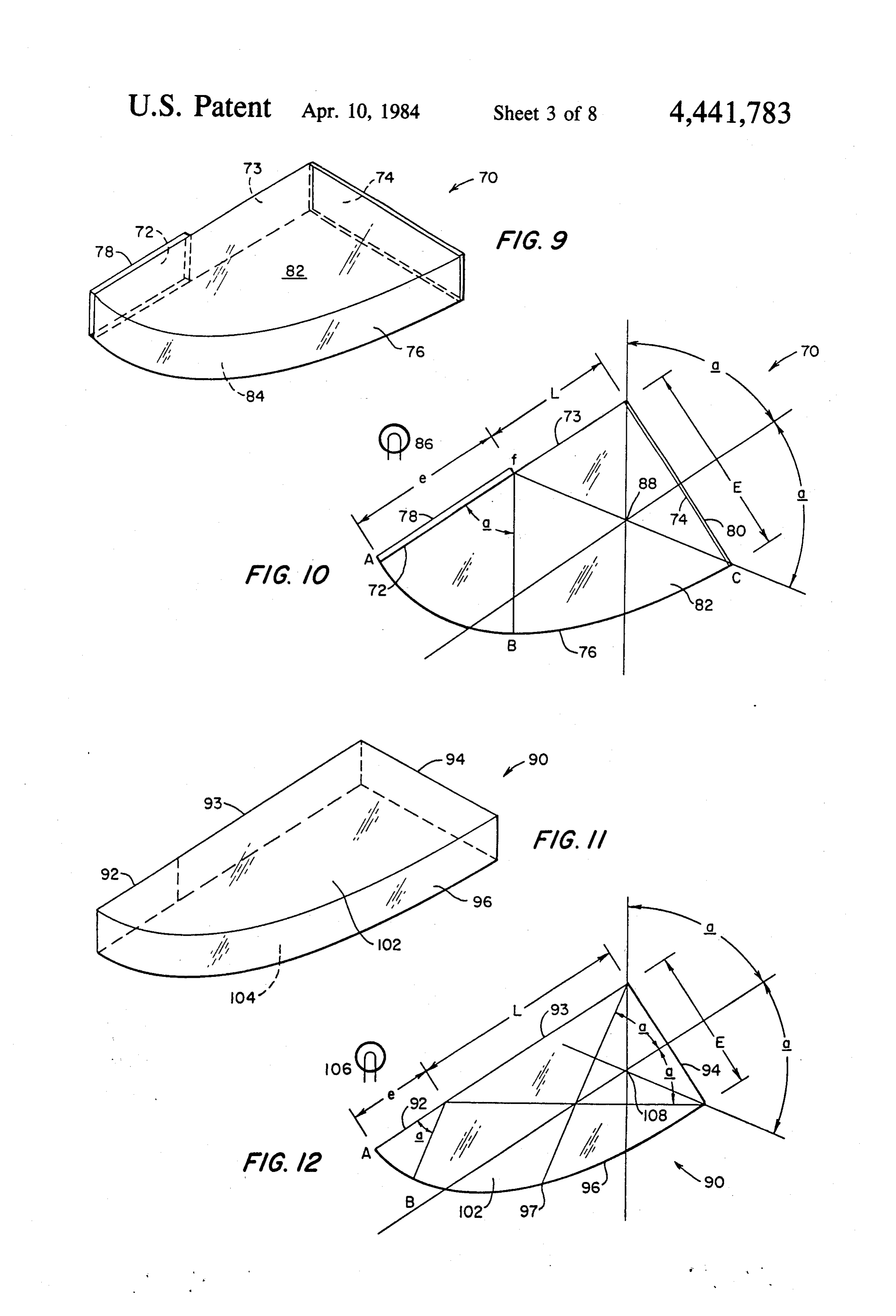
This invention encompasses two geometrical config FIG. 9 is an isometric view of a fourth embodiment of urations, a symmetrical and a asymmetrical diverger, the optical elements of the invention in the form of an each of which may be constructed as a cavity or a di asymmetrical cavity diverger for a starboard running electric. This results in four basic designs for achieving 45 light for a vessel;
the desired horizontal arcs of visilibity for the side FIG. 10 is a plan view of the embodiment of the lights, and two for the stern light (there being no appar invention shwon in FIG. 9;
ent advantage to the use of the asymmetrical diverger FIG. 11 is an isometric view of a fifth embodiment of for the stern light). In addition, three means for project the optical elements of the invention in the form of an ing light into desired vertical arcs of visibility are de 50 asymmetrical dielectric diverger for a starboard run scribed. ning light for a vessel;
The asymmetrical diverger geometry described FIG. 12 is a plan view of the embodiment of the herein does not appear in the published literature. How invention shown in FIG. 11;
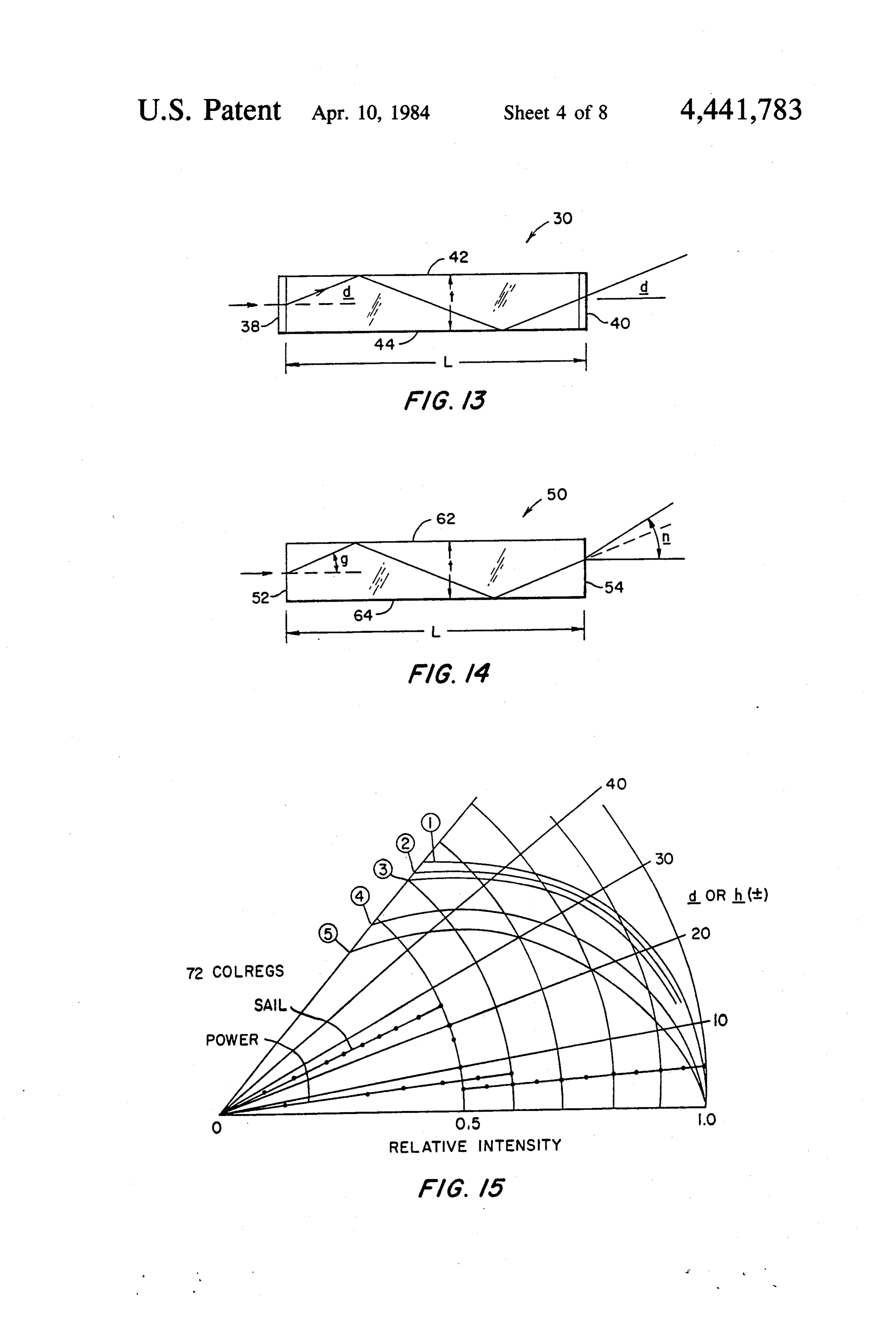
ever, ray tracing and experimental data establish that FIG. 13 is a diagrammatic illustration of the vertical the same behaves in much the same manner as a sym 55 arc of visibility for a cavity diverger having parallel top metrical collimator for purposes of the present inven and bottom surfaces;
tion. FIG. 14 is a diagrammatic illustration of the vertical Due to the technology applied, optical gains can be arc of visibility for a dielectric diverger having parallel achieved in the order of from about three times to about top and bottom surfaces;
ten times the input energy (ignoring reflective losses) 60 FIG. 15 is a graphic representation of the relative depending upon the means used to control the vertical intensities of the vertical arcs of visibility of a dielectric arcs of visibility. Substantially any light source that is diverger and four cavity divergers having parallel top inexpensive to purchase, economical to operate, and and bottom surfaces, the graph also illustrating the mini readily available, even an oil or kerosene latern, may be mum vertical angle requirements set forth in the 72 employed in precision navigational lights. 65 COLREGS;
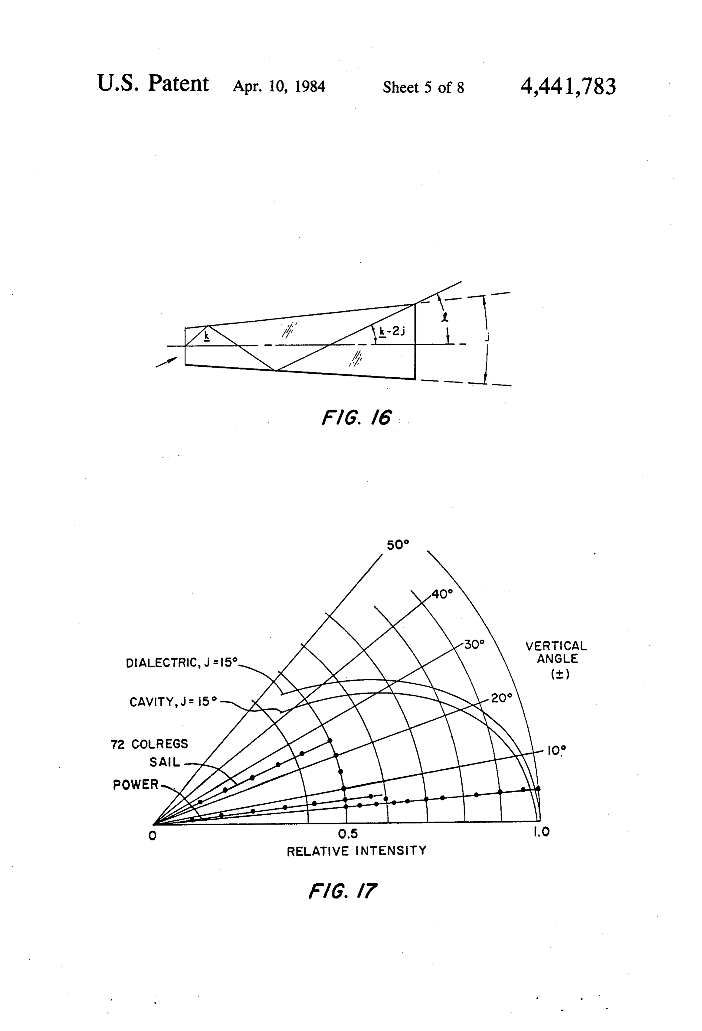
By virtue of the optical elements provided by the FIG. 16 is a diagrammatic illustration of the vertical present invention. navigational lights can now be de arc of visibility for divergers having divergent top and signed and produced which are (1) in precise compli bottom surfaces;
Page 12
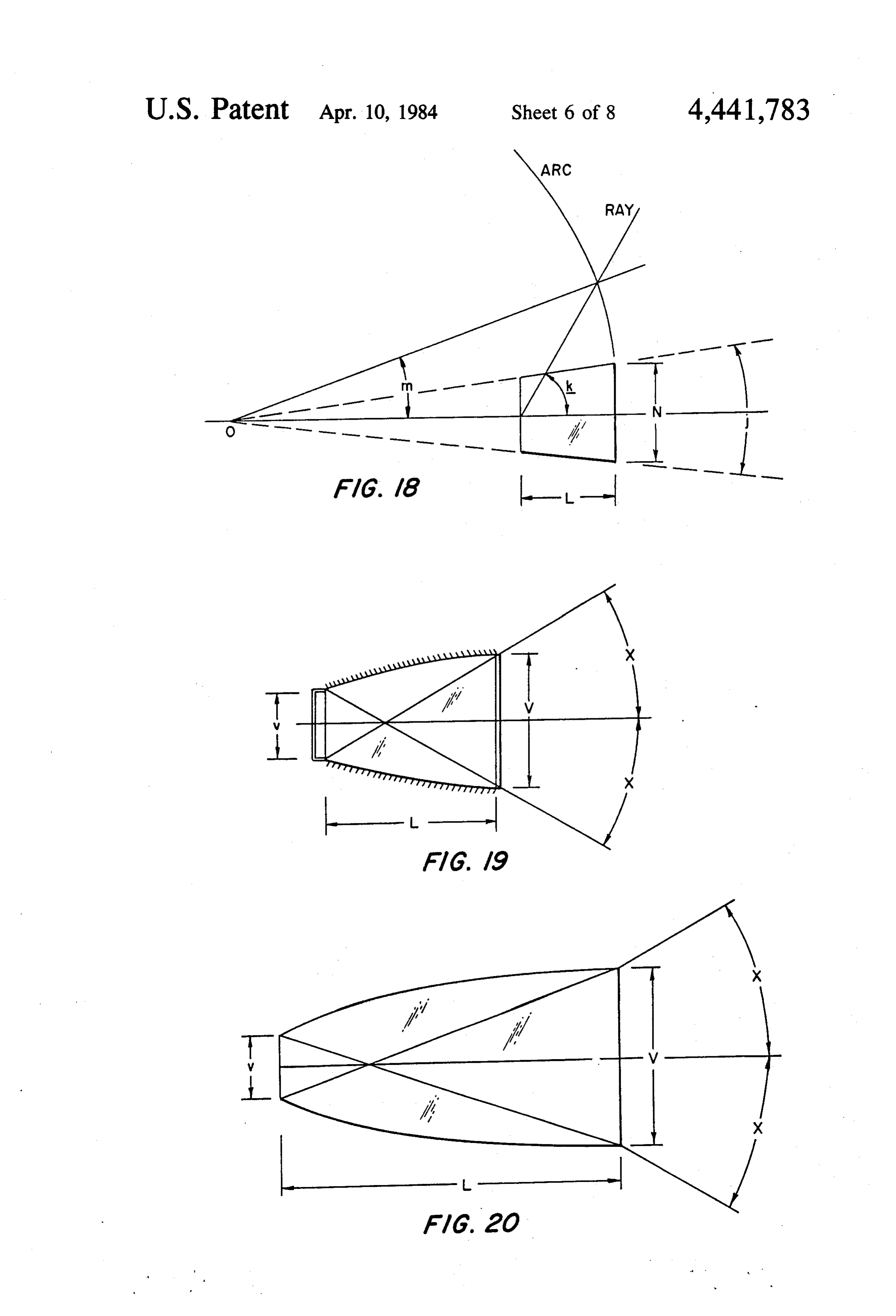
FIG. 17 is a graphic representation of the relative In practice, to provide installation tolerances, the intensities of the vertical arcs of visibility of a dielectric design arc for the side lights must be somewhat greater diverger and a cavity diverger having divergent top and than 112.5 and that of the stern light somewhat greater bottom surfaces, the graph also illustrating the mini than 135 to be in literal compliance with the 72 COL mum vertical angle requirements set forth in the 72 REGS. The selection of the actual arc to be used is left COLREGS; to the manufacturer. For purposes of illustration, the FIG. 18 is a graphic illustration of a method for deter side light diverger diagrams referred to throughout this mining the vertical arc of visibility for a symmetrical description are drawn to an arc of visibility of 2 radians diverger having its top and bottom surfaces diverging at (114.59) for the starboard running light of a vessel. The a selected angle; O collimators for the port running light are merely of FIG. 19 is a side elevation of a symmetrical cavity opposite hand. The equations for the geometry of the diverger for use in projecting light over a precise verti stern light are identical except for the angle. cal arc of visibility;
FIG. 20 is a side elevation of a symmetrical dielectric THE HORIZONTAL ARC OF VISIBILITY diverger for use in projecting light over a precise verti 15 SYMMETRICAL CAVITY DIVERGER cal arc of visibility; FIGS. 1 and 2 illustrate the cavity version of the FIG. 21 is a plan view of a starboard running light for symmetrical vessels provided in accordance with the invention and visibility equaldiverger to two for providing a horizontal arc of radians. In FIG. 2, a is an angle utilizing an asymmetrical diverger; equal to one-half of the desired horizontal arc of visibil FIG.22 is a side view of the navigational light shown 20 ity, i.e., one radian in this illustration. As shown, the in FIG. 21; optical element comprises a hollow cavity 30 bounded FIG. 23 is a horizontal, longitudinal sectional view of a starboard running light utilizing a symmetrical di by a light entry plane 32, a light exit plane 34, and para bolic sides 36. A light diffusing element 38 is placed verger;
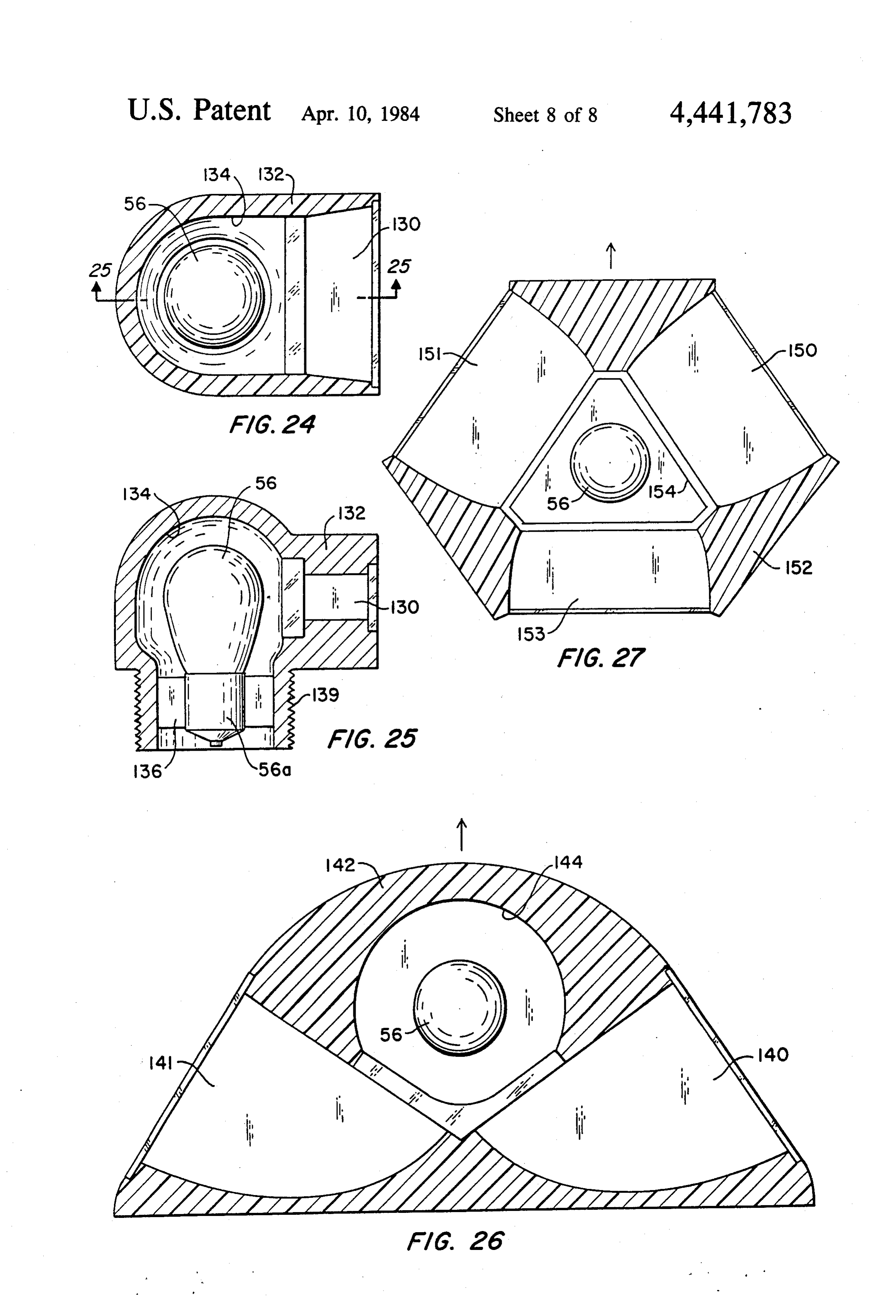
FIG. 24 is a horizontal sectional view of a stern light 25 over or forms the light entry plane, and a transparent cover or lens 40 is placed across or forms the light exit utilizing a symmetrical diverger;
FIG. 25 is a vertical section of the navigational light plane. The two planes are disposed in spaced parallel shown in FIG. 24, the view being taken substantially on referred to relation one another along a common axis, herein to as the diverger axis. Top and bottom cover
FIG. 26 is a horizontal sectional view of a combina 30 elements 42 and 44 complete the physical assembly of tion navigational light ulilizing a pair of asymmetrical the element. Luminous energy for the element is pro divergers and embodying both port and starboard run vided by a lamp 46, which is here shown as being ning lights as provided in accordance with the inven spaced axially from the light entry plane 32, although exact placement is not important.
tion; and
FIG. 27 is a plan view of a three-way combination 35 The geometric construction of the element is as fol light, utilizing three symmetrical divergers and provid lows: Let E (the width of the light exit plane) equal 1 ing port, starboard, and stern lights, all in accordance unit; thene (the width of the light entry plane) is equal with the invention. to sina; and, L (the distance between the entry and exit planes) is equal to (E--e)/(2 tana).
DETALED DESCRIPTION OF THE The parabolic side walls AB and DC have the follow PREFERRED EMBODIMENT ing geometry: parabola AB has its focus at Cand its axis In the accompanying drawings, FIGS. 1 through 12 (which passes through C) parallel to the line BD. It has are concerned with the divergence of light within se a focal length equal to lected or prescribed horizontal arcs of visibility, and
FIGS. 13 through 20 are concerned with the diver 45 e/2(1- sin a) gence of light within vertical arcs of visibility.
Basically, four devices are described, each consisting Parabola DC is the same except that its focus is at B, and of an optical element to be supplied with luminous en its axis is parallel to the line AC.
ergy from any convenient, economical, readily avail The inner surfaces of the parabolic side walls 36 are able source (hereinafter referred to as a "lamp') and to 50 coated with a good quality specularly reflective mate emit light through a lens or filter which may be colored rial, such as silver or aluminum. or clear, over a precise angle of visibility, thereby to The light entering the cavity 30 from lamp 46 facilitate the manufacture of navigational lights fully through the diffuser 38 will leave the light exit plane 34 satisfying all applicable laws and regulations. and front cover 40 between the angles of plus and minus The four basic devices are (1) a symmetrical cavity 55 a with respect to the diverger axis, i.e., a total angle or diverger, (2) a symmetrical dielectric diverger, (3) an arc equal to 2a. If the light entering is diffuse, the lumi asymmetrical cavity diverger, and (4) an asymmetrical nous intensity across the entire arc 2a of visibility will dielectric diverger. be uniform.
In the following description of the application of each The cavity 30 may be of arbitrary height or thickness, of these optical elements to define precise horizontal but its top and bottom surfaces, i.e., the interior surfaces arcs of visibility, two internationally prescribed arcs are of the covers 42 and 44 are coated with a specularly of concern. However, the design equations are applica reflective material. In the simplest form of the cavity ble to any arc of visibility less than 180'. The arcs of diverger the top and bottom covers 42 and 44 comprise concern are 112.5 for the port and starboard running parallel planes, as shown in FIG. 13, but the same may lights (side lights) and 135 for the stern light (and cer 65 also comprise divergent planes as shown in FIG. 16 or tain towing lights). The masthead light arc of visibility parabolic walls as shown in FIG. 20. is specified at 225, and it is provided by the combina The entire cavity is sealed to prevent deterioration of tion of two side lights without colored filters. the reflective surfaces.
Page 13
The virtual source of light, as viewed from any point which is proportionate thereto. To normalize this to the in the arc of visibility, is a perpendicular line through relative intensity on the axis, the factor must be divided the intersection of the two diagonals AC and BD, as by the intensity for b-0.
indicated at point 48. Consequently, the cut-off angles at The resultant relative intensity at the angle c is the two ends of the arc of visibility will be essentially 5 V1-(n sin b)2. A plot of this intensity, derived by ray Zero, tracing, vs the design arc of visibility is shown in FIG.
THE HORIZONTAL ARC OF VISIBILITY 6. The net result is that the on-axis intensity must be SYMMETRICAL DELECTRIC DIVERGER about 1.75 times the minimum prescribed intensity to FIGS. 3 and 4 illustrate the dielectric version of the 10 ensure compliance with the 72 COLREGS. However, symmetrical diverger for providing a horizontal arc of the dielectric diverger is potentially simpler to manufac ture than the cavity diverger and the increased luminos visibility equal to two radians. The optical element ity requirement is partly offset by the perfect efficiency comprises an integral, solid piece or block of transpar ent, light refractive, dielectric material 50 such as glass ofMeans the total internal reflection. or plastic. The external configuration of the block 50 of 5 across thetoarcimprove the uniformity of light intensity of visibility of the dielectric diverger are dielectric material is generally similar to the external configuration of the above-described symmetrical cav described in conjunction with FIGS. 7 and 8. As shown ity dirverger the same having external surfaces defining in FIG. 7, the light energy along the edges of the arc a light entry plane 52, a light exit plane 54, parabolic originates at the opposite corner of the diverger. Specif. sides 56 and top and bottom walls or surfaces 62 and 64. 20 ically, since CD is a parabola having its focus at B and The design equations to define the boundaries of the its axis parallel to AC, the dominant source of light dielectric are identical to those of the symmetrical cav exiting at or near the limits of the light exit plane 54 ity diverger of FIGS. 1 and 2, except that the angle a is emanates from the edges of the light entry plane 52. defined by the equation Consequently, the placement of a prism 69, which is 25 plano-concave in horizontal cross-section, between the sin (SIN OF ANGLE OF ARC OF VISIBILITY light source and the light diffusing surface of the light entry plane 52 will provide a compensating, non uniform energy input distribution which will result in a where n is the refractive index of the dielectric material. more uniform output intensity distribution across the The surface of the dielectric comprising the light 30 arc of visibility. The design of the plano-concave prism entry plane 52 is treated to comprise a light diffusing 69 will, of course, be influence by the light distribution surface, for example, by grinding, frosting, or dimpling. on the exit plane 54, which results from direct illumina Except for the portions 53 nearest the light entry plane tion by the lamp 66 and the energy reflected by the 52, the surfaces of the side walls 56 and the top and walls of the housing (FIGS. 21-27) within which the bottom walls 62 and 64 of the dielectric need not be 35 lamp 66, the prism 69, and the light entry plane 52 are coated with specularly reflective material because the enclosed. The possible variations in lamp type, nominal light striking these surfaces, for all angles of practical lamp position, lamp housing shape, and the reflectivity interest, will be reflected by total internal reflection in of the lamp housing walls are nearly infinite, hence a accordance with Snell's law. However, it is preferable generalized design rule is not possible. However, the to coat at least those portions of the walls between the 40 principles involved as above described will enable those light entry plane 52 and the approximate locations of reasonably skilled in the art to design an appropriate the reference numerals 53. A light source or lamp 66 is prism 69 and/or lamp housing for each application located at or near the axis of the dielectric in spaced contemplated.
relation to the light diffusing surface of the entry plane
THE ASYMMETRICAL CAVITY HORIZONTAL
All light entering the light entry plane 52 from the ARC DIVERGER source 66 will leave the light exit plane 54 within the FIGS. 9 and 10 illustrate the asymmetrical cavity design arc of visibility, and the virtual course of that version of horizontal arc diverger of the invention. The light, in the horizontal plane, will be a perpendicular asymmetrical diverger is a geometrical transform of the line through point 68. 50 symmetrical diverger that has its light entry plane at If the light on the dielectric side of the light entrance right angles to the light exit plane. Its optical perfor plane 52 is diffuse, the luminous intensity throughout mance is identical to the symmetrical diverger. the arc will be relatively uniform, but not as "flat' as As shown in FIGS. 9 and 10, the optical device com that shown for the symmetrical cavity of FIGS. 1 and 2. prises a hollow cavity 70 bounded by a light entry plane This is caused by refraction at the light exit plane. FIG. 55 72, a straight side wall 73 which is an extension of the 5 illustrates the phenomenon.
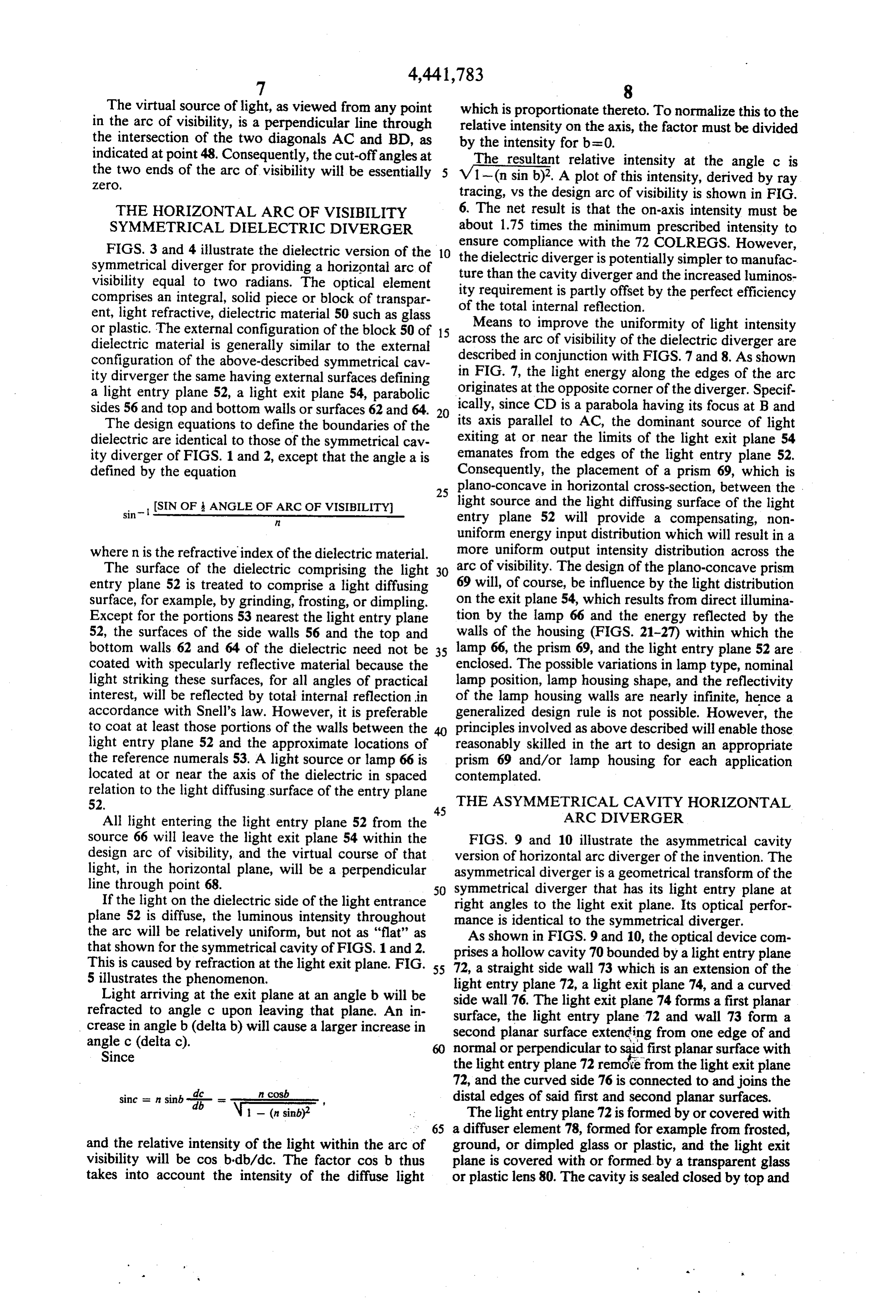
Light arriving at the exit plane at an angle b will be lightwall entry plane 72, a light exit plane 74, and a curved refracted to angle c upon leaving that plane. An in side 76. The light exit plane 74 forms a first planar crease in angle b (delta b) will cause a larger increase in second planarlight surface, the entry plane 72 and wall 73 form a surface extending from one edge of and angle c (delta c). normal or perpendicular to syid first planar surface with Since the light entry plane 72 remote from the light exit plane in cosb 72, and the curved side 76 is connected to and joins the sinc set n sinb-i- see", distal edges of said first and second planar surfaces. (n sinb)? The light entry plane 72 is formed by or covered with 65 a diffuser element 78, formed for example from frosted, and the relative intensity of the light within the arc of ground, or dimpled glass or plastic, and the light exit visibility will be cos b-db/dc. The factor cos b thus plane is covered with or formed by a transparent glass takes into account the intensity of the diffuse light or plastic lens 80. The cavity is sealed closed by top and
Page 14
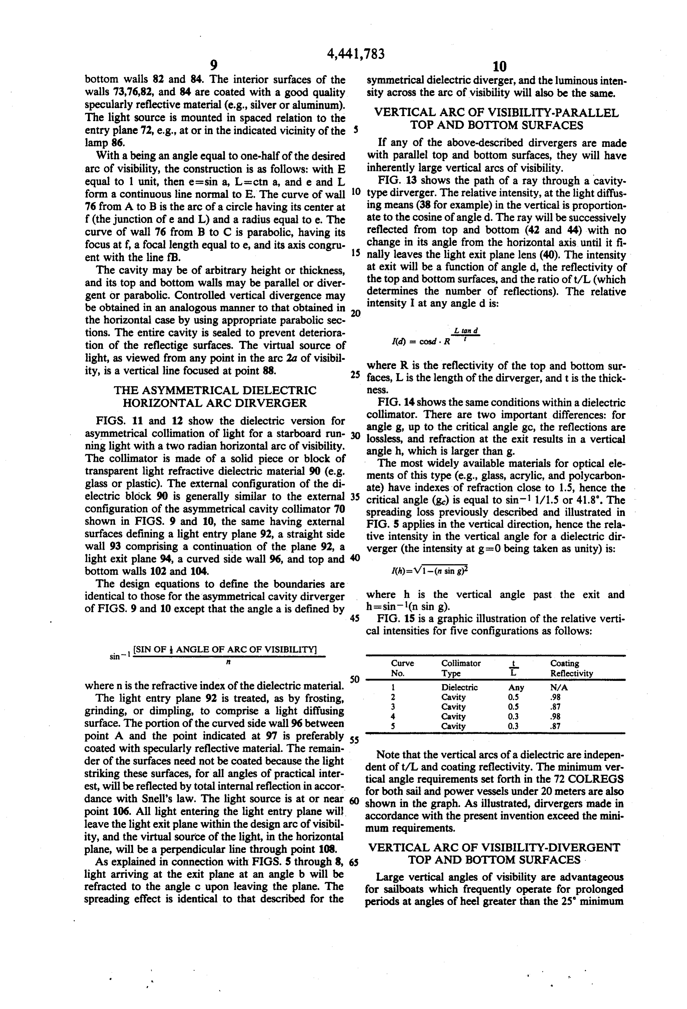
bottom walls 82 and 84. The interior surfaces of the symmetrical dielectric diverger, and the luminous inten walls 73,76,82, and 84 are coated with a good quality sity across the arc of visibility will also be the same. specularly reflective material (e.g., silver or aluminum). VERTICAL ARC OF VISIBILITY-PARALLEL The light source is mounted in spaced relation to the TOP AND BOTTOM SURFACES entry plane 72, e.g., at or in the indicated vicinity of the lamp 86. If any of the above-described dirvergers are made With a being an angle equal to one-half of the desired with parallel top and bottom surfaces, they will have arc of visibility, the construction is as follows: with E inherently large vertical arcs of visibility. equal to 1 unit, then e=sin a, L=ctna, and e and L O FIG. 13 shows the path of a ray through a cavity form a continuous line normal to E. The curve of wall type dirverger. The relative intensity, at the light diffus 76 from A to B is the arc of a circle having its center at ing means (38 for example) in the vertical is proportion f(the junction of e and L) and a radius equal to e. The ate to the cosine of angled. The ray will be successively curve of wall 76 from B to C is parabolic, having its reflected from top and bottom (42 and 44) with no focus at f, a focal length equal to e, and its axis congru change in its angle from the horizontal axis until it fi ent with the line fB. nally leaves the light exit plane lens (40). The intensity The cavity may be of arbitrary height or thickness, at exit will be a function of angled, the reflectivity of and its top and bottom walls may be parallel or diver the top and bottom surfaces, and the ratio oft/L (which gent or parabolic. Controlled vertical divergence may determines the number of reflections). The relative be obtained in an analogous manner to that obtained in 20 intensity I at any angle d is:
the horizontal case by using appropriate parabolic sec tions. The entire cavity is sealed to prevent deteriora L. tand tion of the reflectige surfaces. The virtual source of I(d) = cosd. R light, as viewed from any point in the arc 2a of visibil where R is the reflectivity of the top and bottom sur ity, is a vertical line focused at point 88. 25 faces, L is the length of the dirverger, and t is the thick THE ASYMMETRICAL DELECTRIC eSS.
HORIZONTAL ARC DRVERGER FIG. 14 shows the same conditions within a dielectric FIGS. 11 and 12 show the dielectric version for collimator. There are two important differences: for asymmetrical collimation of light for a starboard run 30 angle g, up to the critical angle gc, the reflections are lossless, and refraction at the exit results in a vertical ning light with a two radian horizontal arc of visibility. angleh, which is larger than g.
The collimator is made of a solid piece or block of The most widely available materials for optical ele transparent light refractive dielectric material 90 (e.g. ments of this type (e.g., glass, acrylic, and polycarbon glass or plastic). The external configuration of the di ate) have indexes of refraction close to 1.5, hence the . electric block 90 is generally similar to the external critical angle (go) is equal to sin. 1/1.5 or 41.8. The configuration of the asymmetrical cavity collimator 70 spreading loss previously described and illustrated in shown in FIGS. 9 and 10, the same having external FIG. 5 applies in the vertical direction, hence the rela surfaces defining a light entry plane 92, a straight side tive intensity in the vertical angle for a dielectric dir wall 93 comprising a continuation of the plane 92, a verger (the intensity at g=0 being taken as unity) is: light exit plane 94, a curved side wall 96, and top and 40 bottom walls 102 and 104.
The design equations to define the boundaries are identical to those for the asymmetrical cavity dirverger where h is the vertical angle past the exit and of FIGS. 9 and 10 except that the angle a is defined by h=sin(n sing).
FIG. 15 is a graphic illustration of the relative verti cal intensities for five configurations as follows:
sin
(SIN OF ANGLE OF ARC OF VISIBILITY
Curve Colimator -- Coating
where n is the refractive index of the dielectric material. Dielectric Any N/A The light entry plane 92 is treated, as by frosting, 2
Cavity
Cavity
grinding, or dimpling, to comprise a light diffusing 4. Cavity 0.3 98 surface. The portion of the curved side wall 96 between s Cavity 0.3 87 point A and the point indicated at 97 is preferably 55 coated with specularly reflective material. The remain Note that the vertical arcs of a dielectric are indepen der of the surfaces need not be coated because the light dent oft/L and coating reflectivity. The minimum ver striking these surfaces, for all angles of practical inter tical angle est, will be reflected by total internal reflection in accor for both sailrequirements and power set forth in the 72 COLREGS vessels under 20 meters are also dance with Snell's law. The light source is at or near shown in the graph. As illustrated, dirvergers made in point 106. All light entering the light entry plane will accordance with the present invention exceed the mini leave the light exit plane within the design arc of visibil mum requirements.
ity, and the virtual source of the light, in the horizontal plane, will be a perpendicular line through point 108. VERTICAL ARC OF VISIBILITY-OVERGENT As explained in connection with FIGS. 5 through 8, TOP AND BOTTOM SURFACES : light arriving at the exit plane at an angle b will be Large vertical angles of visibility are advantageous refracted to the angle c upon leaving the plane. The for sailboats which frequently operate for prolonged spreading effect is identical to that described for the periods at angles of heel greater than the 25 minimum
Page 15
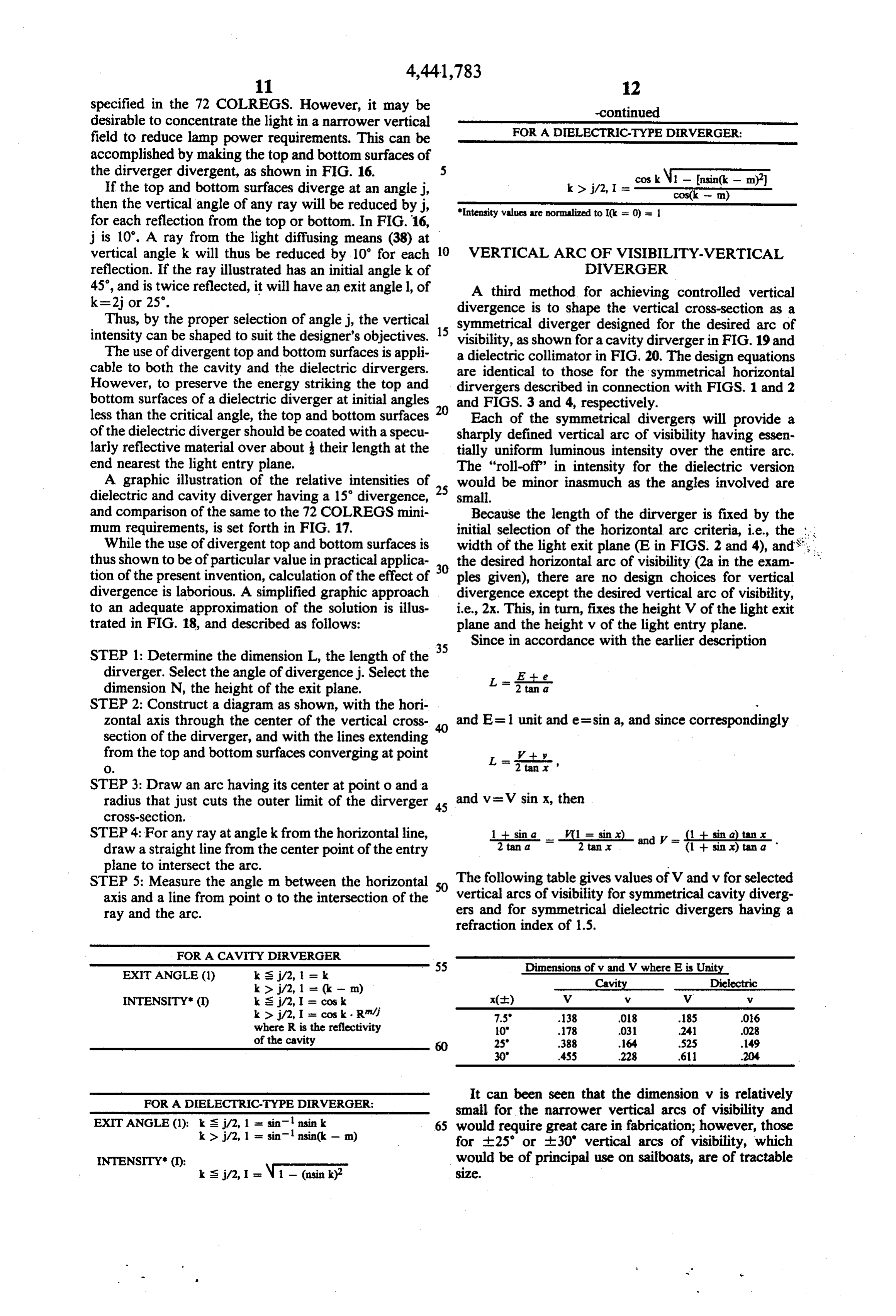
specified in the 72 COLREGS. However, it may be -continued desirable to concentrate the light in a narrower vertical FOR A DELECTRC-TYPE DERVERGER: field to reduce lamp power requirements. This can be accomplished by making the top and bottom surfaces of the dirverger divergent, as shown in FIG. 16. 5 cos kW - insin(k - m? If the top and bottom surfaces diverge at an anglej, k > j/2, I = - as a then the vertical angle of any ray will be reduced byj, Intensity values are normalized to Ick is 0) = 1 for each reflection from the top or bottom. In FIG.16, j is 10'. A ray from the light diffusing means (38) at vertical angle k will thus be reduced by 10' for each 10 VERTICAL ARC OF VISIBILITY-VERTICAL reflection. If the ray illustrated has an initial angle k of DIVERGER 45, and is twice reflected, it will have an exit anglel, of A third method for achieving controlled vertical k=2jor 25. divergence is to shape the vertical cross-section as a Thus, by the proper selection of anglej, the vertical symmetrical diverger designed for the desired arc of intensity can be shaped to suit the designer's objectives. 15 visibility, as shown for a cavity dirverger in FIG. 19 and The use of divergent top and bottom surfaces is appli a dielectric collimator in FIG. 20. The design equations cable to both the cavity and the dielectric dirvergers. are identical to those for the symmetrical horizontal However, to preserve the energy striking the top and dirvergers described in connection with FIGS. 1 and 2 bottom surfaces of a dielectric diverger at initial angles 20 and FIGS. 3 and 4, respectively. less than the critical angle, the top and bottom surfaces Each of the symmetrical divergers will provide a of the dielectric diverger should be coated with a specu sharply defined vertical arc of visibility having essen larly reflective material over about their length at the tially uniform luminous intensity over the entire arc. end nearest the light entry plane. The "roll-off" in intensity for the dielectric version A graphic illustration of the relative intensities of would be minor inasmuch as the angles involved are dielectric and cavity diverger having a 15 divergence, 25 small.
and comparison of the same to the 72 COLREGS mini Because the length of the dirverger is fixed by the mum requirements, is set forth in FIG. 17. initial selection of the horizontal arc criteria, i.e., the . . While the use of divergent top and bottom surfaces is width of the light exit plane (E in FIGS. 2 and 4), and Sg thus shown to be of particular value in practical applica the desired horizontal arc of visibility (2a in the exam tion of the present invention, calculation of the effect of 30 ples given), there are no design choices for vertical divergence is laborious. A simplified graphic approach divergence except the desired vertical arc of visibility, to an adequate approximation of the solution is illus i.e., 2x. This, in turn, fixes the height V of the light exit trated in FIG. 18, and described as follows: plane and the height v of the light entry plane. Since in accordance with the earlier description
STEP 1: Determine the dimension L, the length of the 35 dirverger. Select the angle of divergence j. Select the B Ee dimension N, the height of the exit plane. L =2
STEP 2: Construct a diagram as shown, with the hori
Zontal axis through the center of the vertical cross and E = 1 unit and e=sina, and since correspondingly section of the dirverger, and with the lines extending from the top and bottom surfaces converging at point
O. L = itn,
STEP 3: Draw an arc having its center at point o and a radius that just cuts the outer limit of the dirverger and v=V sin x, then
STEP 4: For any ray at angle k from the horizontal line, 1 Esin a -- ( = sin x) and = 1 -- sin a) tanx draw a straight line from the center point of the entry 2 tan a T 2 tanx (1 + sin x) tan a plane to intersect the arc.
STEP 5: Measure the angle m between the horizontal 50 The following table gives values of V and v for selected vertical arcs of visibility for symmetrical cavity diverg axis and a line from point o to the intersection of the ray and the arc. ers and for symmetrical dielectric divergers having a refraction index of 1.5.
EXIT ANGLE (1) k is j/2, l = |k Dimensions of v and V where E is Unity k > j/2, l = (k - m) Cavity Dielectric INTENSITY (I) k Sj/2, I = cos k x(t) V W V w k > /2, I = cos k. R/ 7.5 138 O8 .185 06 where R is the reflectivity O 178 031 .241 028 of the cavity 60 25 388 164 52S 149 30 4S5 228 611 204
FOR A DELECTRC-TYPE DERVERGER
It can been seen that the dimension v is relatively small for the narrower vertical arcs of visibility and
EXIT ANGLE (1): k sj/2, 1 = sin nsink 65 would require great care in fabrication; however, those k > j/2, 1 = sin nsin(k - m) for 25 or E30' vertical arcs of visibility, which INTENSITY (I): would be of principal use on sailboats, are of tractable
Page 16
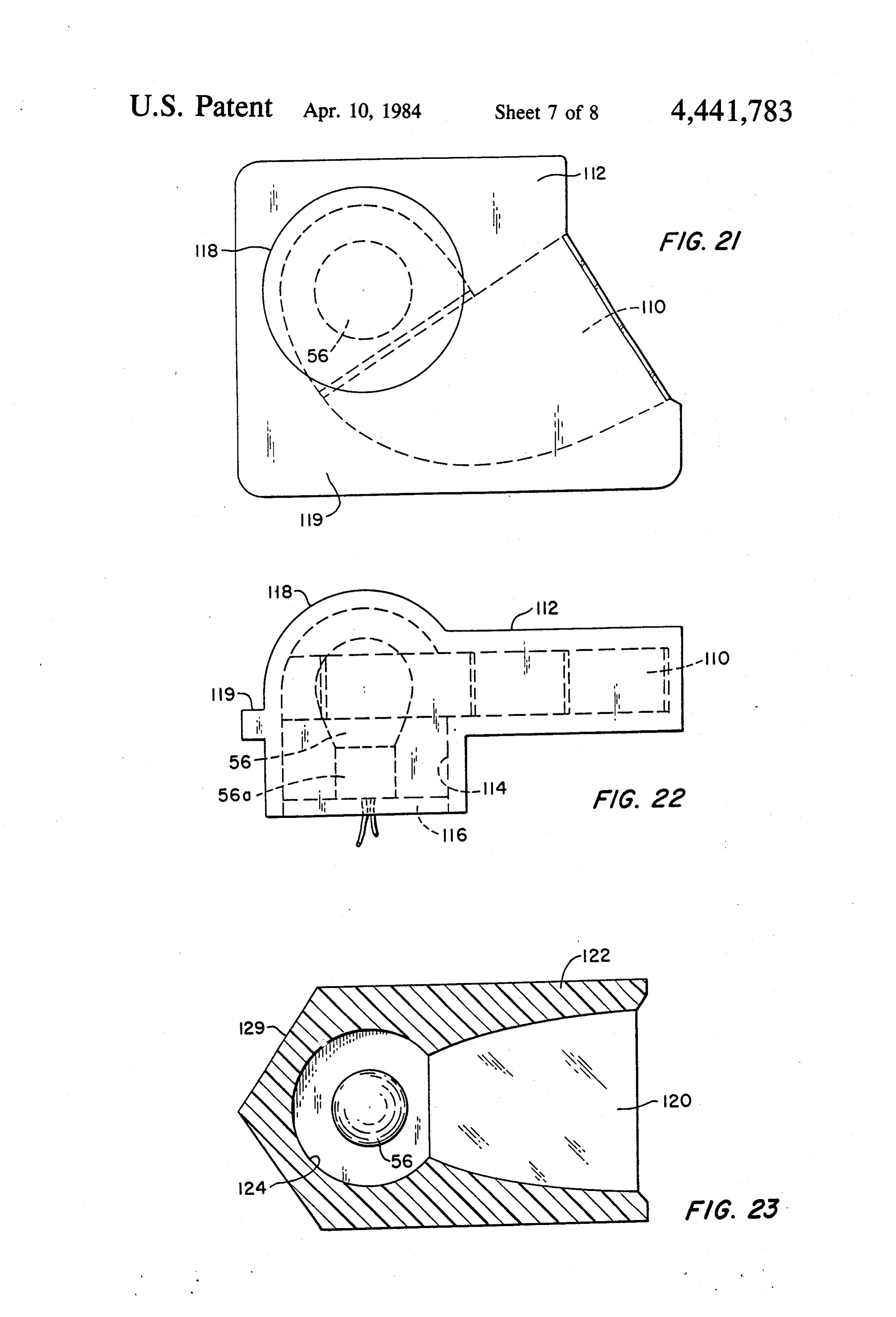
NAVIGATIONAL LIGHTS EMBODYING THE mounting surface 129 parallel with the forward margin DVERGERS of the arc of visibility of the optical element 120 for mounting the light in proper position on a side bulkhead
Construction of navigational lights using the diverg of a vessel. Alternatively, the housing could be pro ers described requires: vided with an integral mounting flange as in the em bodiment of FIGS. 21 and 22, or the same could be a. Means for providing red or green coloration for the mounted on an appropriate bracket.
port and starboard side lights, respectively, and yel Port running lights would be the same as the star low for the 135 horizontal arc of visibility lights board running lights illustrated in FIGS. 21 through 23, which are used as towing lights. 10 but of opposite hand.
b. A housing which holds the collimator in proper A stern light for a vessel is shown in FIGS. 24 and 25 alignment, provides a space for the lamp and its as comprising, by way of example, a symmetrical di holder, and incorporates means for securing the light verger 130, a lamp 56 and lamp socket 56a adjacent the to the appropriate part of the vessel. entry plane of the dirverger, a housing 132 fitted or
For cavity-type divergers, coloration may be pro or molded about the dirverger, and having therein a space vided by the use of an appropriate filter as the light exit recess 134 for removable reception of the lamp and plane cover or lens (40 or 80) or the light entry plane socket, mounting and a spring type bracket 136 for removably the lamp and socket in said recess. In this diffuser (38 or 78). In the dielectric diverger, the basic diverger can be made of the appropriate color or a thin 20 embodiment, the housing 132 is provided with a cylin colored filter can be coupled to the exit plane (54 or 94) drical threaded extension 139, coaxial with the lamp recess, for mounting the light on a vessel.
of the dielectric material. While the use of a colored lamp would achieve the same result, this would require A combination light providing both the port and lamps of special manufacture and would invite error in starboard running lights for a vessel, but utilizing only a lamp replacement. Thus, it is preferred to use a colored 25 single light source, is shown in FIG. 26. In the embodi dielectric material or colored filters as described. ment illustrated, a pair of asymmetrical divergers 140 The housing of the light can be made of any material, and 141 are mounted with their light entry planes adja including metal or opaque plastic. Basically, the hous cent one another and facing into a lamp receiving space ing can be a fairly simple enclosure, for enclosing the or recess 144 in which a single lamp 56 is removably diverger and for defining a recess or space for reception 30 mounted. The lamp thus illuminates both divergers and of a lamp and its holder; the housing being provided the two divergers provide, respectively, a starboard with suitable means for gaining access to the lamp re running light (140) and a port running light (141). A ceiving space for installation, service, and replacement housing 142 provides a mounting for the divergers, of the lamp. The interior surfaces of the walls defining defines the lamp space 144, and comprises an all the lamp receiving space should be coated with a dura 35 weather enclosure for the diverger and the lamp. ble, flat, diffuse white coating to maximize the effi A combination light utilizing symmetrical divergers ciency of the fixture. Alternatively, a specular reflector is illustrated in FIG. 27. In the embodiment shown, may be used to direct all available light onto the light three divergers 150, 151, and 153 are employed to pro entry plane of the diverger. However, the best unifor vide a three-way navigational light comprising a star mities over the arcs of visibility will be obtained when 40 board running light (150), a port running light (151) and the light entry plane is uniformly illuminated with dif a stern light (153). A housing 152 defines a coated lamp fuse light. The lamp need have no special characteris receiving space or recess 154 for receiving a lamp 56, tics, nor is its exact placement of great importance. and mounts the three symmetrical divergers with their Representative examples of navigational lights em entry planes facing into and receiving light from the bodying the described optical elements and the de 45 single source. This thus forms an excellent combination scribed housing criteria are shown in FIGS. 21 through for mounting on the mast of a vessel. The Figure also 27. shows how two symmetrical divergers may be utilized Referring to FIGS. 21 and 22, a starboard running to provide port and starboard lights, simply by omission light is shown as comprising an asymmetrical diverger of the diverger 153 and substitution therefor of opaque 110 (which may be the same as any of the asymmetrical 50 housing material.
divergers previously described), a housing 112 fitted or The invention thus provides a broad spectrum of molded about the diverger and having a lamp receiving extremely effective navigational lights, which are eco space or recess 114 shaped and dimensioned to receive nomical to purchase, use and maintain. the selected light source or lamp, a removable closure Since the design is not dependent upon a point or line element 116 for closing said recess, and a lamp 56 and 55 source of luminous energy, and the lamp cavity is re lamp socket 56a mounted on the removable closure for flective and all of the light is effectively utilized, signifi insertion in and removal from the housing to facilitate cant optical gain is achieved. The gain for a side light is bulb replacement. Alternatively, the dome 118 enclos dependent upon the configuration selected for the verti ing the top of the lamp housing could be made remov cal arc of visibility and is as follows, ignoring reflection able for gaining access to the lamp. In this embodiment, and transmission losses:
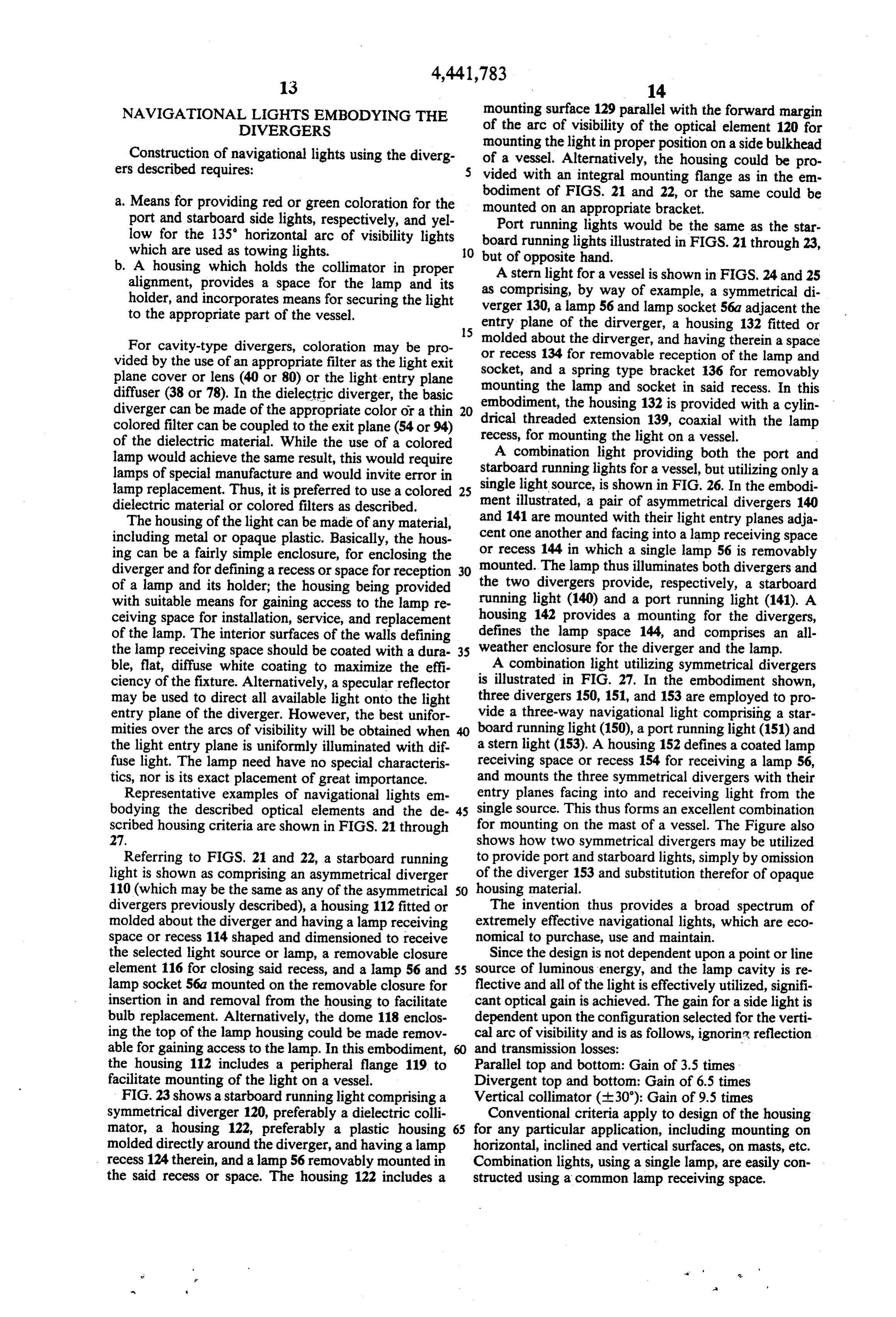
the housing 112 includes a peripheral flange 119 to Parallel top and bottom: Gain of 3.5 times facilitate mounting of the light on a vessel. Divergent top and bottom: Gain of 6.5 times FIG. 23 shows a starboard running light comprising a Vertical collimator (30): Gain of 9.5 times symmetrical diverger 120, preferably a dielectric colli Conventional criteria apply to design of the housing mator, a housing 122, preferably a plastic housing 65 for any particular application, including mounting on molded directly around the diverger, and having a lamp horizontal, inclined and vertical surfaces, on masts, etc. recess 124 therein, and a lamp 56 removably mounted in Combination lights, using a single lamp, are easily con the said recess or space. The housing 122 includes a structed using a common lamp receiving space.
Page 17
For navigational lights, the cavity type divergers can 1. An optical element for navigational lights and the be made of any marine metal or durable plastic, with a like, comprising an asymmetrical light diverger having glass or plastic diffuser and cover lens. The specularly a light entry plane for receiving diffuse light, a light exit reflective surfaces may be of aluminum, silver, or other plane positioned in spaced normal relation to said light material having high specular reflectivity. The light 5 entry plane, and at least one curved surface, which is in diffusing surface may be formed by grinding, frosting, part parabolic, connecting said planes for diverging dimpling, and/or other similar techniques. The basic diffuse light from said light entry plane into a virtual cavity comprised of top, bottom and side walls may be line of luminous energy, the light from said line being cast or molded in a single piece, or the sides, top and 10 arctransmitted through said light exit plane over a precise bottom may be separately formed and then secured of visibility.
together. 2. An optical element as set forth in claim 1, wherein Dielectric divergers may be cast or molded of any said said diverger comprises a first planar surface defining light exit plane, a second planar surface extending durable transparent material such as glass or plastic, e.g., acrylic or polycarbonate. For the surfaces which 15 from one edge of and normal to said first plane surface, said light entry plane being defined by the portion of require coating, any material having high specular re said second planar surface remote from said first planar flectivity is suitable. Light diffusing surfaces may be surface, and a curved surface joining the distal edges of formed the same as for the cavity divergers. said first and second planar surfaces, the portion of said In view of the foregoing, it is now apparent that the curved surface adjacent said light entry plane compris present invention provides optical elements, and navi 20 ing substantially an arc of a circle and the remainder of gational lights embodying said elements, which are (1) said curved surface being parabolic.
in precise compliance with the 72 COLREGS and the 3. An optical element as set forth in claim 2, wherein implementing U.S. Statute; (2) capable of being manu said diverger comprises a block of light refractive di factured in such small sizes as to be ideally suited to electric material having external surfaces comprising small vessels without need for elongated screens; (3) less 25 said planar surfaces and said curved surface. costly than prior art lights in terms of both initial invest 4. An optical element as set forth in claim 3, wherein ments and cost of operation, especially in comparison to the portion of the curved surface adjacent said light the lights purportedly designed to comply with the entry plane is coated with a specularly reflective mate COLREGS; and (4) powered by an inexpensive and 30 rial.
readily available light source. 5. An optical element as set forth in claim 2, wherein And it is to be understood that the optical elements planarsaid diverger comprises a reflective cavity defined by embodied in our invention are applicable to other lights, plane, alight diffusing means comprising said light entry planar wall joined with said diffusing means and such as aircraft runway lights.
While certain preferred embodiments of the inven 35 acomprising transparent the remainder of said second planar surface, lens connected at one edge to said planar tion have been illustrated and described, it is to be un wall normal thereto and defining said first planar sur derstood that various changes, rearrangements and face, and a curved wall having reflective interior sur modifications may be made therein without departing faces connected to and joining the distal ends of said from the scope of the invention as defined by the ap light diffusing means and said lens and comprising said pended claims. curved surface.
What is claimed is: k k k k sk
Provenance
- Collection
- Cited prior art
- Original PDF
- patentimages.storage.googleapis.com →
- Filed
- 1982-09-23
- Pages
- 17
- Method
- pdftotext (the PDF's own text layer) + pdftoppm 300dpi page scans
- Source
- Google Patents bibliographic record
- Granted
- 1984-04-10
- Inventors
- Alexander J. Houghton; Thomas M. Knasel; Science Applications Inc
- Transcribed from
- patentimages.storage.googleapis.com →