patent · US4382656
Non-imaging optical energy transfer system
10 May 1983
Page 1 — bibliographic record
United States Patent (19) 11) 4,382,656 Gilby 45) May 10, 1983
(54) NON-IMAGING OPTICAL ENERGY OTHER PUBLICATIONS
TRANSFER SYSTEM
Williamson, "Cone Channel Condenser Optics," (75 Inventor: Anthony C. Gilby, Foxboro, Mass. J.O.S.A., vol. 42, No. 10, Oct. 1952, pp. 712-715. Marshall, "Tapered Light Guide Condenser: A Design 73) Assignee: The Foxboro Company, Foxboro, Approach," Conf. Proc. of SPIE Vol. 176 Guided Wave Mass. Opt. Systems & Devices II, Washington, D.C., Apr. 1979, (21) Appl. No.: 206,249 pp. 161-167.
22 Filed: Nov. 12, 1980 Primary Examiner-John D. Lee Attorney, Agent, or Firm-Andrew T. Karnakis 51) Int. C. ................................................ GO2B 5/14 (57) ABSTRACT 52 U.S.C. .............................. 350/96.28; 350/96.10; A non-imaging optical energy transfer system includes a 350/320; 356/326 tapered light pipe and associated field lens as its central (58) Field of Search ............... 250/343; 350/55, 96.10, energy transfer mechanism. The light pipe/lens combi 350/96.28, 320; 356/326 nation is located between two separate sections of the (56) References Cited system which individually have the same throughput or
pupil sizes. The transfer system is disclosed used in 3,535,507 10/1970 Sugino ......................... 350/96.10 X combination with a circular variable filter-absorption 3,536,434 10/1970 Frank .... ... 350/96.28 X cell infrared spectrometer and an internal reflection 3,670,157 6/1972 Bragg.... ... 350/96.28 X spectrometer, employing a multiple internal reflection 3,861,809 1/1975 Hall, Jr. .......................... 250/343 X crystal.
4,070,090 iv.1978 Farr et al. .................... 350/96.28 X 4,105,332 8/1978 Hohne et al. . ... 350/96.28 X 4, 175,864. 1 1/1979 Gilby ................................... 356/326 20 Claims, 6 Drawing Figures
Page 2
Drawing sheet — no readable text.
Page 3
Drawing sheet — no readable text.
Page 4
Drawing sheet — no readable text.
Page 5
SUMMARY OF THE INVENTION
NON-IMAGING OPTICAL ENERGY TRANSFER The present invention overcomes the disadvantages
SYSTEM
and limitations of the prior art by providing a tapered
FIELD OF THE INVENTION light pipe and associated field lens as the "central" en This invention relates generally to optical systems ergy transfer mechanism in a non-imaging optical en and particularly to such systems employed in instru ergy transfer system. The tapered light pipe is consid ments which involve the transfer of optical energy be matchesbeatatitsthe ered to center of the optical system because it end beams having different f/# require tween spatially distinct locations, 10 ments as energy is transferred from one section of the BACKGROUND OF THE INVENTION system to another. Coincident with transferring beam foci, the tapered light pipe/lens combination matches
Optical energy transfer systems that combine a series pupils of lenses and mirrors have been known for many years, section. in the small end section to pupils in the large end and in fact such systems have played a major role in the 15 In a preferred embodiment of the invention to be commercial development of certain analytical instru subsequently disclosed in detail, an infrared spectrome mentation. An example of such an instrument is a spec ter utilizes a tapered light pipe of rectangular cross trometer which passes a light beam through a sample section as one element of the optical connecting link cell to measure the absorption spectrum of an unknown between the source of monochromatic infrared energy gas in a predetermined wavelength region. 20 and the sample absorption cell. A beam focus of the Two important characteristics of the types of optical source is produced through a fast beam at the small end system described herein are that they must be capable of opening of the light pipe which serves as the filter defin changing the f/# of the beam as it traverses the system ing slit. The beam exiting the large end of the pipe is while at the same time substantially matching the eten sufficiently reduced in solid angle to match the optical due or optical throughput from one part of the instru 25 requirements of the cell which essentially are preestab ment system to another to avoid energy loss through lished by the area of the cell's limiting pupil (object vignetting. This is especially significant in today's com mirror), the area of the beam focus which is at the large mercial optical instruments where limitations of size and end of the pipe and the separation between them. These cost result in widely varying optical requirements be quantities establish the etendue of the absorption cell. tween spatially distinct locations within the instrument. 30 The etendue of the source/monochromator section is In the particular example of an infrared spectrometer, designed to be the same.
it is desirable to obtain the highest signal level from the The limiting pupil is simultaneously transferred onto available source power by passing as much infrared the other side of the light pipe by a second optical ele energy as possible into the system through the mono 35 ment-namely a field lens adjacent the large end of the chromator slit. Therefore, an input beam with as large a pipe. The lens in combination with the correctly chosen solid angle as possible that does not sacrifice spectral taper of the light pipe provides for substantially total resolution (e.g., f/1.5 for a circular variable filter based energy transfer between pupils thereby maintaining the spectrometer) is used to form the first image (beam etendue through the system. Additionally the use of a focus) of the source at the slit. The divergence of the 40 tapered light pipe eliminates the function of two rela beam as it traverses the cell is however more severely tively strong lenses (or equivalent mirrors) in a compa limited due to optical aberrations and practical size rable lens/mirror design. This permits a more simpli requirements of the absorption cell itself and the associ fied, compact construction which aids in the design of a ated optics. Typically, the beam passing into and out of portable instrument.
the cell is f/4.5. 45
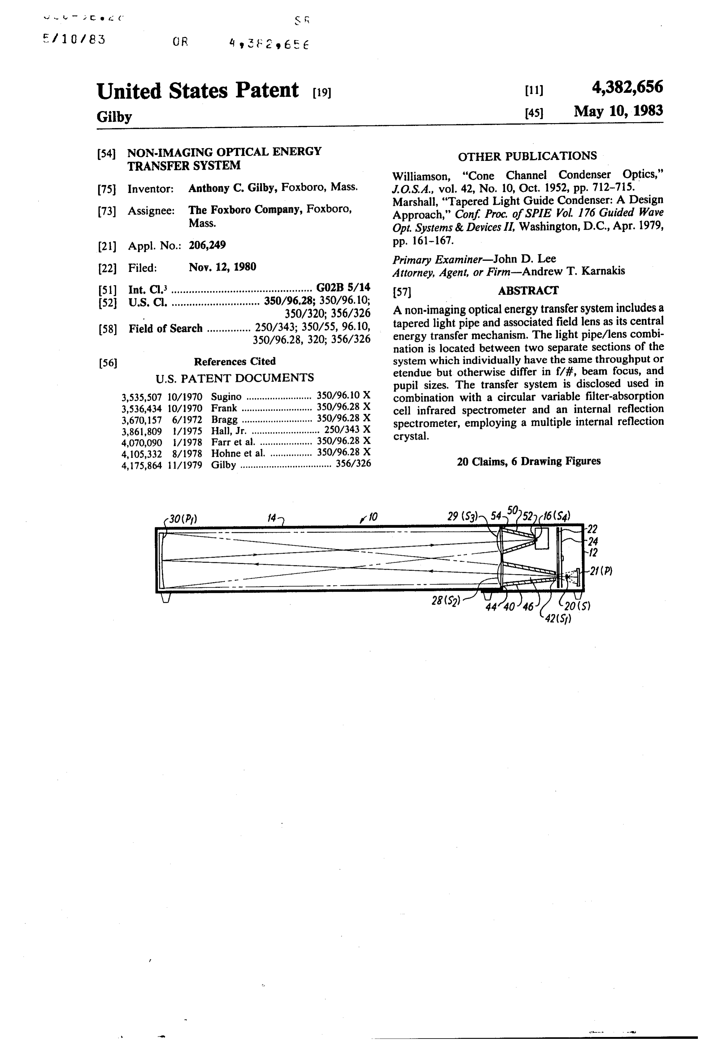
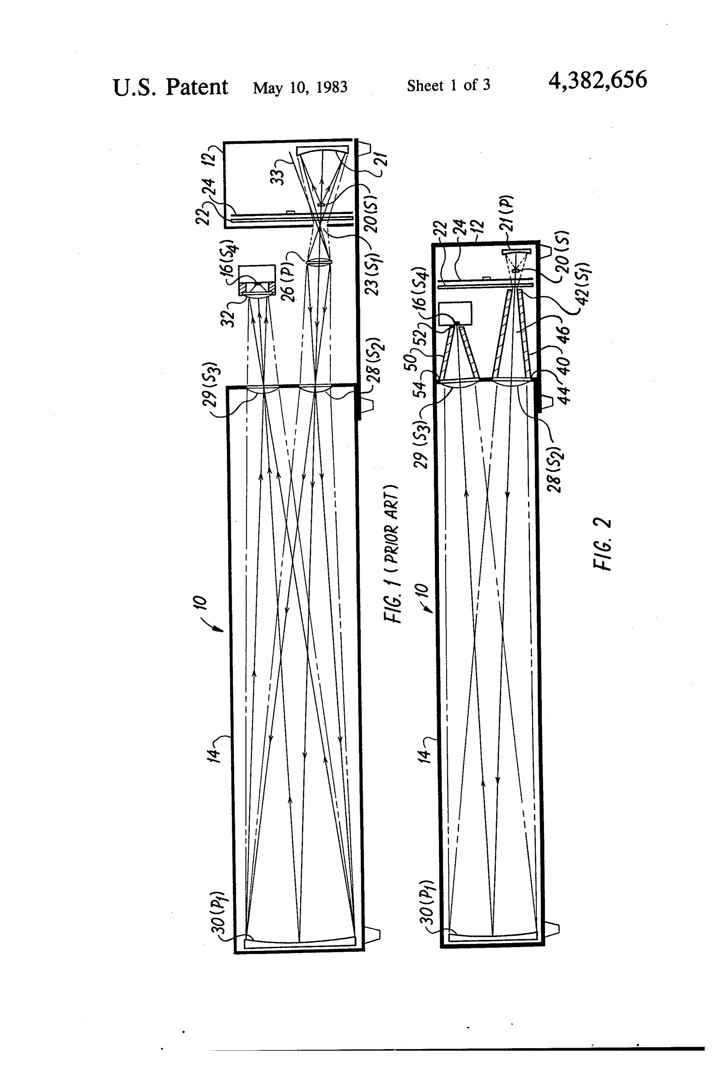
The product of the area of the slit and the solid angle DESCRIPTION OF THE DRAWINGS of the beam at the slit establishes the optical throughput Other aspects and advantages of the present inven or etendue of the spectrometer system. For best instru tion will be best understood by the following detailed ment performance, the etendue in other sections of the description taken in accordance with the following system, such as the absorption cell, should be the same 50 drawings wherein:
such that energy throughput is maximized even though FIG. 1 is an optical schematic of a prior art optical the f/# requirements may vary widely. To minimize energy transfer system used in combination with a spec vignetting energy losses, pupil dimensions defined in trometer;
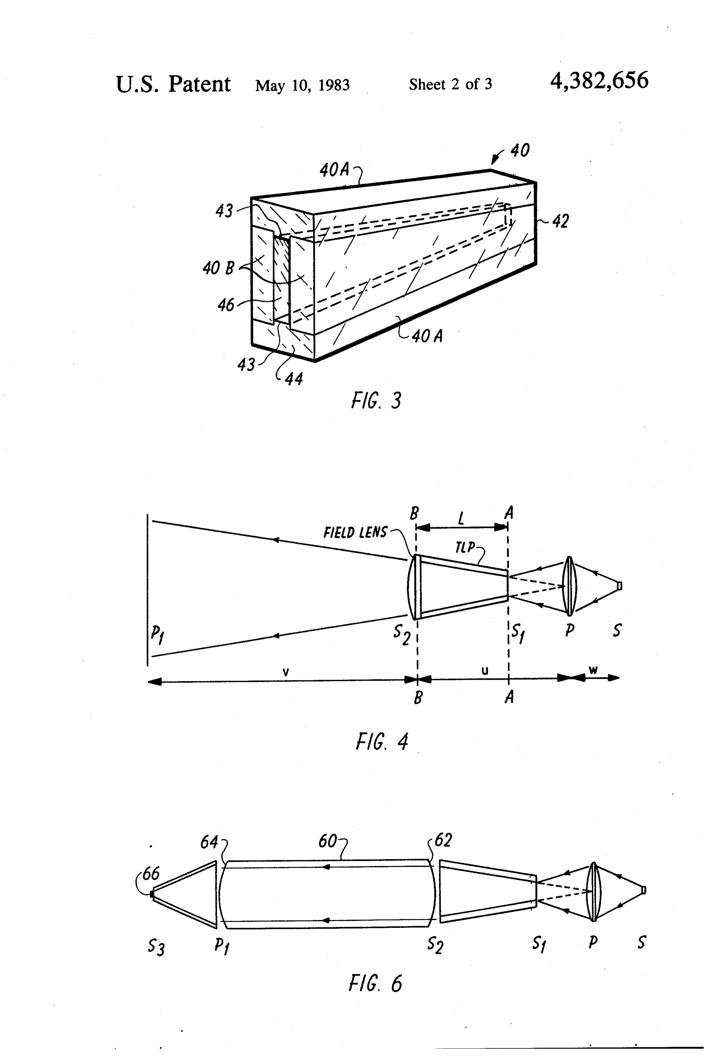
respective sections should be preserved while the sub FIG. 2 is an optical schematic of the preferred em stantially different solid angles of the beams in various 55 bodiment of an optical energy transfer system con sections of the device are simultaneously matched. structed in accordance with the present invention also Optical energy transfer systems of the prior art pres used in combination with a spectrometer; ent certain drawbacks. Particularly, when very wide FIG. 3 is a perspective view of a tapered light pipe angle or "fast' beams are involved, a conventional for the embodiment of FIG. 2;
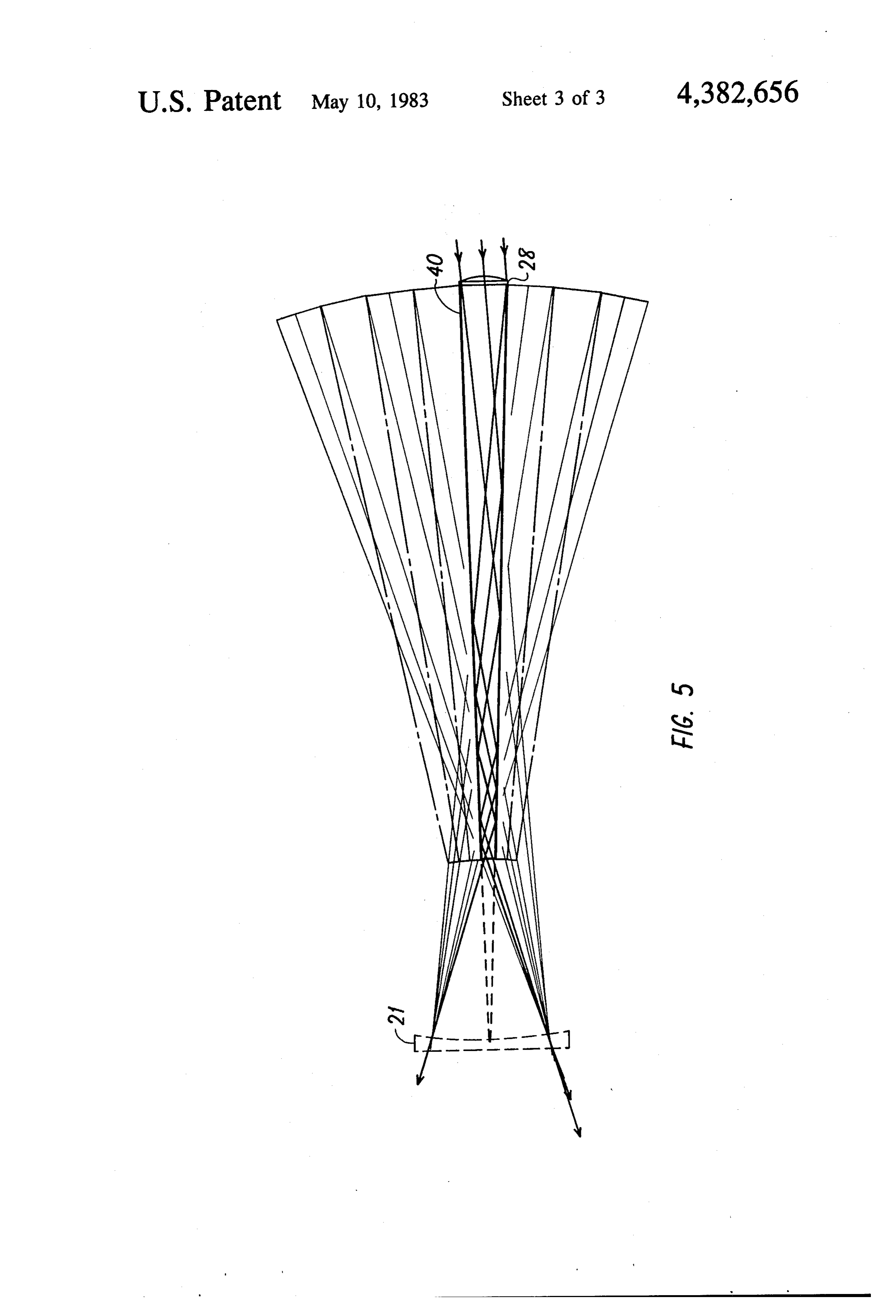
lens/mirror system requires strong (i.e., short focal FIG. 4 is a diagrammatic representation of the optical length) lenses to produce a desired f/# change with energy transfer system of the present invention illustrat minimal vignetting. However, such lenses produce ab ing construction techniques for a tapered light pipe/lens errations and Fresnel reflections and thus are them combination to achieve maximum optical throughput; selves sources of lost energy for the system. Further FIG. 5 is a ray trace through the light pipe/lens com these lenses are space-consuming and field lenses as well 65 bination of the embodiment of FIG. 2; and as focusing lenses are required to achieve the desired FIG. 6 is an optical schematic of the energy transfer result, all of which adds to the overall size and weight system of FIG. 2 used in combination with a multiple of the instrument system. internal reflection crystal.
Page 6
DESCRIPTION OF THE PREFERRED
Turning now to FIG. 2, a more complete understand
EMBODIMENT
ing of the optical energy transfer system of the present invention will become apparent. FIG. 2 also shows the
In order to obtain a clearer understanding of the system used in combination with a spectrometer and to construction and operation of the present invention, an particularly emphasize certain advantages of the pres explanation of prior art optical energy transfer systems ent transfer system both spectrometers are configured used in combination with spectrometers will be helpful. with sample absorption cells of identical length, with Referring to FIG. 1, there is shown in schematic form a the dimensions of the remainder of the instrument being conventional infrared spectrometer 10 which is made O scaled to that length. Attention is particularly directed up of three major assemblies, an instrument head 12, a to the portion of the beam from the chopper/filternet sample absorption cell 14, and a pyroelectric detector work up to the cell entrance window 28. The remainder 16. The optical transfer system of the spectrometer of the device, with the exception of the detector optics transcends all three assemblies. which will be subsequently described, is identical to The head 12 has contained therein a light source 20, 15 that discussed above and for ease in comparison like a source mirror 21, and circular variable filter 22, which reference numerals have been retained between the two produce a first image S1 of the source of appropriate figures. Accordingly, no further explanation of these components is deemed necessary.
infrared wavelength at a rectangular exit slit 23. Also As shown in FIG. 2, a tapered light pipe 40 is posi depicted is the usual rotating chopper 24 which breaks tioned in the optical the continuous beam into a series of pulses to enable the 20 the absorption cell beam
path between the head 12 and
Tapered light pipes of various detector and associated signal processing system to configurations have been used for some time now as respond to changes in energy reaching it while at the energy collectors or concentrators, most often with the same time rejecting much of the electrical noise in the large end accepting light rays from a source and focus system.
ing through internal reflections within the
Intermediate the head and sample cell, a silver bro 25 optical energy onto a detector positioned directly pipe the mide focusing lens 26 is positioned to produce a second small end. Further details on the properties andatcon the image S2 of the source at an entrance window 28 of the sample cell. The entrance window is actually a field lens struction of such tapered light pipes may be had by reference to an article entitled "Cone Channel Con which propagates an image P of an object mirror 30 denser Optics" by D. E. Williamson published in the placed at the far end of the cell onto the focusing lens 30 such that the objective mirror is fully illuminated by the Journal
of the Optical Society of America, Vol. 42 No.
October 1952. Thus, what Williams and others pro beam emerging from the entrance window. The object pose regarding tapered light pipes was that they were mirror is the limiting pupil P1 of the sample cell and useful as one termination point of the optical system and together with the associated beam focus at the cell en not as part of an energy transfer mechanism. However, trance window defines the etendue of the complete 35 in the present embodiment, the light pipe, which has a optical system. hollow inner channel 46 of rectangular cross-section The object mirror 30 then reflects the beam onto the (see FIG. 3), forms a closed channel in the center of the cell exit window 29 where a third image S3 of the source optical system with its small end 42 coincident with a is produced. The beam passing out of the cell 14 is beam focus in the head and its large end 44 being at the ultimately directed onto a detector lens 32 for produc beam focus of the cell. Specifically, the small end of the ing a fourth source image S4 at the detector 16. The pipe protrudes up to and nearly touches the filter 22, so response produced by this image is then processed ac as to positionally coincide with a beam focus (source cording to well known techniques to provide a spectral image S). Additionally the area of the small end open analysis of the sample gas contained iri the cell. ing matches the cross-section of this beam focus and The beam entering and exiting the cell 14 is of sub 45 thus serves as the filter defining slit. Meanwhile the stantially higher f/# (e.g., f/4.5) than that of the beam large end butts against the cell entrance window/field focused through the slit 23 (e.g., f/1.5). In this instance lens 28, which is also a beam focus of cross-sectional beam angle matching for energy transfer is accom area identical to that of the large end opening. plished by the focusing lens 26. As shown the lens 26 After passing through the absorption cell 14 and has a very short focal length and as such is subject to 50 reflecting from the object mirror 30, the beam is di chromatic and other aberrations as well as surface re rected to the cell exit window 29 which concentrates flections, all of which result in lost energy to the system the rays on a second tapered light pipe 50 located with and a corresponding poorer signal-to-noise ratio for a its large end 54 covering the exit window. This light given power input. pipe is of similar construction to the light pipe 40 but It is also apparent that despite the fact that the image 55 because of the shorter distance between the exit win P of the limiting pupil P1 is propagated out of the cell 14 dow and the detector 16 it has a more severe taper. It by means of the field lens 28 onto the focusing lens 26, should also be mentioned that the detector is positioned the pupil image is not transferred to the input section directly at the small end 52 of the pipe. Hence this (i.e., instrument head 12) of the device as evidenced by tapered light pipe functions as an energy collector of the back-projected extreme ray 33 which does not im the type mentioned above and explained in considerable pinge on the source mirror. Hence numerous rays are detail in the aforementioned Williamson article. lost to the transfer system. Absent another field lens A comparison of FIGS. 1 and 2 shows, aside from the positioned at the slit 23 or substantially increasing the elimination of strong focusing lenses, that it is possible size of the source mirror 21, optical throughput has to shorten the distance between the head 12 and the cell been lost. It is not practical to eliminate this undesirable 65 14. Such compact dimensions not only enhance the vignetting by taking such steps because the very short design of portable instrumentation but also reduce at focal lengths of the optical components involved would mospheric interference by providing shorter optical produce other more severe losses. beam paths external to the absorption cell. While at the
Page 7
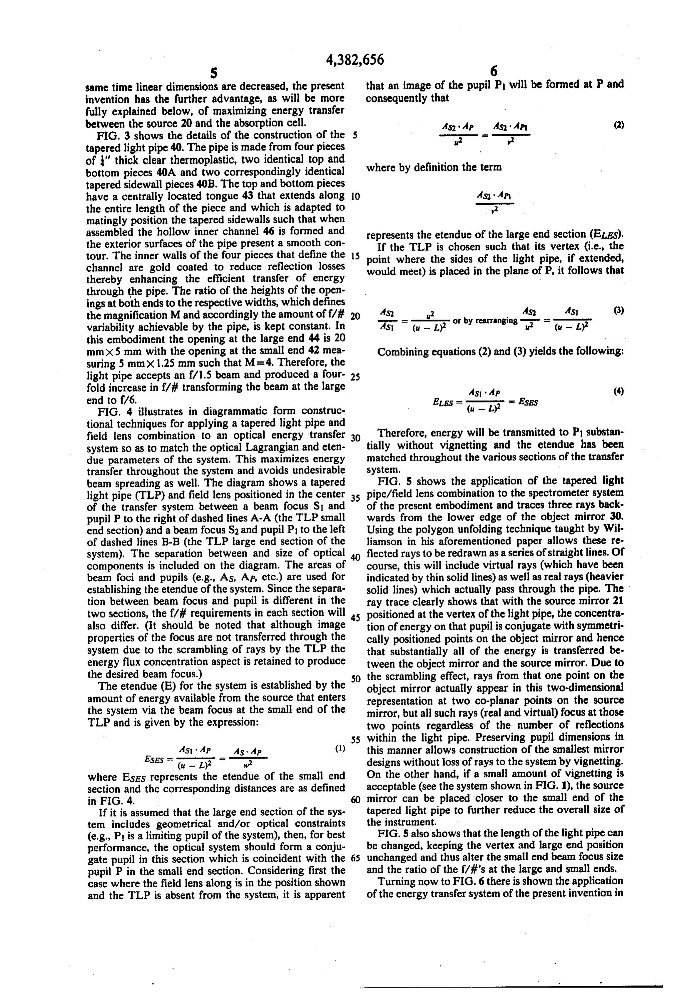
same time linear dimensions are decreased, the present that an image of the pupil P will be formed at P and invention has the further advantage, as will be more consequently that fully explained below, of maximizing energy transfer between the source 20 and the absorption cell. MS MP As MP (2) FIG, 3 shows the details of the construction of the 2 tapered light pipe 40. The pipe is made from four pieces of ' thick clear thermoplastic, two identical top and where by definition the term bottom pieces 40A and two correspondingly identical tapered sidewall pieces 40B. The top and bottom pieces have a centrally located tongue 43 that extends along 10 MS MP the entire length of the piece and which is adapted to 2 matingly position the tapered sidewalls such that when assembled the hollow inner channel 46 is formed and represents the etendue of the large end section (ELEs). the exterior surfaces of the pipe present a smooth con If the TLP is chosen such that its vertex (i.e., the tour. The inner walls of the four pieces that define the 15 point where the sides of the light pipe, if extended, channel are gold coated to reduce reflection losses would meet) is placed in the plane of P, it follows that thereby enhancing the efficient transfer of energy through the pipe. The ratio of the heights of the open ings at both ends to the respective widths, which defines 4s (3) the magnification M and accordingly the amount off/i 20 MS u? or by rearranging sun. variability achievable by the pipe, is kept constant. In As (u - L) this embodiment the opening at the large end 44 is 20 mmX5 mm with the opening at the small end 42 mea Combining equations (2) and (3) yields the following: suring 5mm x 1.25 mm such that M = 4. Therefore, the light pipe accepts an f/1.5 beam and produced a four 25 fold increase in f/# transforming the beam at the large MS MP (4) end to f/6. ELES = = ESES FIG. 4 illustrates in diagrammatic form construc (u - L) tional techniques for applying a tapered light pipe and field lens combination to an optical energy transfer 30 Therefore, energy will be transmitted to P substan system so as to match the optical Lagrangian and eten tially without vignetting and the etendue has been due parameters of the system. This maximizes energy matched throughout the various sections of the transfer transfer throughout the system and avoids undesirable system.
beam spreading as well. The diagram shows a tapered FIG. 5 shows the application of the tapered light light pipe (TLP) and field lens positioned in the center 35 pipe/field lens combination to the spectrometer system of the transfer system between a beam focus S1 and of the present embodiment and traces three rays back pupil P to the right of dashed lines A-A (the TLP small wards from the lower edge of the object mirror 30. end section) and a beam focus S2 and pupil P to the left Using the polygon unfolding technique taught by Wil of dashed lines B-B (the TLP large end section of the liamson in his aforementioned paper allows these re system). The separation between and size of optical 40 flected rays to be redrawn as a series of straight lines. Of components is included on the diagram. The areas of course, this will include virtual rays (which have been beam foci and pupils (e.g., AS, AP, etc.) are used for indicated by thin solid lines) as well as real rays (heavier establishing the etendue of the system. Since the separa solid lines) which actually pass through the pipe. The tion between beam focus and pupil is different in the ray trace clearly shows that with the source mirror 21 two sections, the f/# requirements in each section will 45 positioned at the vertex of the light pipe, the concentra also differ. (It should be noted that although image tion of energy on that pupil is conjugate with symmetri properties of the focus are not transferred through the cally positioned points on the object mirror and hence system due to the scrambling of rays by the TLP the that substantially all of the energy is transferred be energy flux concentration aspect is retained to produce tween the object mirror and the source mirror. Due to the desired beam focus.) 50 the scrambling effect, rays from that one point on the The etendue (E) for the system is established by the object mirror actually appear in this two-dimensional amount of energy available from the source that enters representation at two co-planar points on the source the system via the beam focus at the small end of the mirror, but all such rays (real and virtual) focus at those TLP and is given by the expression: two points regardless of the number of reflections 55 within the light pipe. Preserving pupil dimensions in
As AP As AP (1) this manner allows construction of the smallest mirror ESES = (u - L) w? designs without loss of rays to the system by vignetting. where ESES represents the etendue of the small end On the other hand, if a small amount of vignetting is section and the corresponding distances are as defined acceptable (see the system shown in FIG. 1), the source in FIG. 4. mirror can be placed closer to the small end of the If it is assumed that the large end section of the sys tapered light pipe to further reduce the overall size of tem includes geometrical and/or optical constraints the instrument.
(e.g., P is a limiting pupil of the system), then, for best FIG. 5 also shows that the length of the light pipe can performance, the optical system should form a conju be changed, keeping the vertex and large end position gate pupil in this section which is coincident with the 65 unchanged and thus alter the small end beam focus size pupil P in the small end section. Considering first the and the ratio of the f/#'s at the large and small ends. case where the field lens along is in the position shown Turning now to FIG. 6there is shown the application and the TLP is absent from the system, it is apparent of the energy transfer system of the present invention in
Page 8
combination with a multiple internal reflection (MIR) section having a small f/# requirement and said crystal 60 used to make attenuated total reflection nea second section having a higher f/# requirement; surements. The MIR crystal is of the same general con a tapered light pipe positioned within the optical struction as the type disclosed in U.S. Pat. No. 4,175,864 beam path between said sections with its small end with the exception that the entrance face of the present 5 positioned at the extended beam focus in said first crystal is made convex. The most compact light path section, with its large end positioned at the ex through the crystal, and therefore the smallest crystal tended beam focus in said second section; for a given etendue, is achieved if a source image is focusing means positioned intermediate said large end placed at one end of the crystal and a pupil at the other. and said second section pupil; This can be achieved by using a TLP in combination O said first section pupil being established at the vertex with an MIR crystal having a convex entrance face. of said tapered light pipe by the combination of The source mirror and exit slit are respectively the pupil said focusing means and said light pipe such that P and source image S1 in the small end section of the the concentration of energy on said first section device while the entrance face 62 and the exit face 64 of pupil is conjugate with symmetrically positioned the crystal are the source image S2 and pupil P1 within 15 points on said second section pupil and the product the large end section. Energy is transferred from the of the area of the extended beam focus and the solid source to the exit face of the crystal and according to angle of the beam respectively at each end of said the principles discussed in detail above, the height of the light pipe is equal whereby energy is transferred beam exiting the crystal is controlled to enable energy between both of said pupils substantially without to be transferred substantially without vignetting. Curv 20 vignetting loss.
ing the exit face and placing an energy-collecting TLP 2. Apparatus as claimed in claim 1 wherein said beam of the type disclosed by Williamson permits efficient focus and said pupil in said first section respectively are energy transfer to a detector 66 positioned at the end of of similar shape to their counterparts in said second this TLP.
It is apparent that the foregoing discussion concern 25 section but differ in cross-sectional area and separation. 3. Apparatus as claimed in claim 1 wherein said ta ing beam focus and pupil areas to match the etendue between different parts of an optical system can be also pered inner light pipe includes wall means defining a hollow channel extending along the entire length of said defined in terms of Lagrangians. Therefore it is possible pipe opening out at said large and small ends for passing to match optical systems having astigmatism to those optical energy therethrough.
that do not by using a tapered light pipe having a vertex 30 in one plane which does not coincide with its vertex in nel4.has Apparatus as claimed in claim 3 wherein said chan a constant cross-sectional shape.
the orthogonal plane.
It is believed that many of the advantages of the is 5.rectangular.Apparatus as claimed in claim 4 wherein said shape present energy transfer system over conventional lens systems have been demonstrated in the foregoing de 35 6. Apparatus as claimed in claim 3 wherein said wall tailed description, for example: means are gold coated to reduce reflection losses as said 1. An equivalent system requiring a minimum of three optical energy is passed through said pipe. lenses, two of which are strong lenses, is reduced to one ing7.means Apparatus as claimed in claim 1 wherein said focus is a field lens positioned at said large end.
low power lens and a tapered light pipe.
2. Pupil dimensions are preserved thereby reducing 40 8. Apparatus as claimed in claim 1 wherein said ta sizes of components while at the same time eliminating pered light pipe is made of solid material. undesirable vignetting. 9. For use with an infrared spectrometer of the type 3. The tapered light pipe/lens combination is more having an extended source of infrared energy, and an compact than the equivalent all-lens system and aids in absorption cell with entrance and exit windows, said the design of a portable instrument. 45 cell and said source forming distinct sections between Other aspects, advantages and features of the present which optical energy is to be transferred, each section invention' will be apparent to those of skill in the art. It including means for defining respective extended beam will also be apparent that many other changes may be foci and associated pupils thereby establishing an f/# possible without departing from the spirit and scope of requirement within each section, the f/# requirements this invention. For example, throughout the foregoing, SO in said cell section differing from those in said source reference has only been made to tapered light pipes section, improved energy transfer apparatus compris having hollow channels; however, the principles dis ing:
cussed above apply equally as well to tapered light a tapered light pipe positioned within the optical pipes made of solid dielectric material and indeed may beam path between said source and said cell sec find application in the rapidly expanding field of fiber 55 tions with its small end positioned at the extended optics. Accordingly the foregoing detailed description beam focus in said source section, with its large end is considered illustrative only and not to be limited positioned at the extended beam focus in said cell; except by the scope of the following claims. focusing means located between said large end and I claim: the pupil in said cell section; 1. Apparatus for non-imaging energy transfer com 60 the pupil in said source section being established at prising: the vertex of said tapered light pipe by the combi an extended source of optical energy; nation of said focusing means and said light pipe first and second sections spatially separated from one such that the concentration of energy on said another between which said optical energy is to be source section pupil in conjugate with symmetri transferred; 65 cally positioned points on the pupil in said said cell means within each of said sections for defining an section and the product of the area of the extended extended beam focus and associated pupil thereby beam focus and the solid angle of the beam respec establishing an f/# requirement therein, said first tively at each end of said light pipe is equal
Page 9
whereby energy is transferred between both of said pupil is conjugate with symmetrically positioned pupils substantially without vignetting loss. points on said one section pupil and the product of 10. Apparatus as claimed in claim 9 wherein the pupil the area of the extended beam focus and the solid in said cell section is an object mirror and the pupil in angle of the beam respectively at each end of said said source section is a source mirror. light pipe is equal whereby energy is transferred 11. Apparatus as claimed in claim 10 wherein said between both of said pupils substantially without source mirror is positioned at the vertex of said light vignetting loss.
pipe. 16. Apparatus as claimed in claim 15 wherein said 12. Apparatus as claimed in claim 9 wherein said beam focus and said pupil in said one section respec focusing means is a field lens positioned at the large end 10 tively are of similar shape to their counterparts in said of said pipe. other section but differ in cross-sectional area and sepa 13. Apparatus as claimed in claim 12 wherein said ration.
field lens is the entrance window of said cell and said 17. Apparatus as claimed in claim 15 wherein said large end of said pipe is directly adjacent said entrance other section includes as its pupil a source mirror which window. 5 forms a beam focus in said other section, said light exit 14. Apparatus as claimed in claim 9 wherein said light face being a pupil in said one section. pipe includes a hollow inner chamber along its entire 18, Apparatus as claimed in claim 17 wherein said length opening out at both said large and small ends light entrance face is positioned at said large end, said with the small end opening serving as the filter defining entrance face having a convex curvature and serving as slit of the spectrometer. 20 15. In an internal reflection spectrometer of the type said focusing means thereby matching said exit face having in one section a multiple internal reflection crys pupil to said source mirror pupil. 19. Apparatus as claimed in claim 18 wherein said tal having respective light entrance and exit faces for light exit face has a convex curvature for producing making attenuated total reflection measurements after another receiving optical energy from another section of the 25 20. A beam method focus in said one section.
for transferring energy between first spectrometer at said light entrance face of said crystal, and second spatially separated sections of an optical non-imaging energy transfer apparatus comprising: apparatus wherein each of said sections includes an means within each of said sections for defining an extended beam focus and associated pupil thereby extended beam focus and associated pupil for establish establishing an f/# requirement therein, one of said 30 ing both an f/# requirement and etendue within each sections having a high f/# requirement and the section, the f/# requirements in each section being other of said sections having a smaller f/# require different but the etendues the same, said method com ment; prising the steps of:
a tapered light pipe positioned within the optical positioning a tapered light pipe within the optical beam path between said sections with its small end 35 beam path between said sections with the ends of positioned at the extended beam focus in said other said pipe positionally coinciding with the respec section, with its large end positioned at the ex tive extended beam foci and with the projected tended beam focus in said one section; vertex of said light pipe coinciding with the pupil focusing means positioned intermediate said large and adjacent the small end of the pipe; and said one section pupil; 40 forming a conjugate of the pupil located in said first said other section pupil being established at the vertex section in said second section whereby energy is of said tapered light pipe by the combination of transferred between both of said pupils substan said focusing means and said light pipe such that tially without vignetting loss.
the concentration of energy on said other section
Provenance
- Collection
- Cited prior art
- Original PDF
- patentimages.storage.googleapis.com →
- Filed
- 1980-11-12
- Pages
- 9
- Method
- pdftotext (the PDF's own text layer) + pdftoppm 300dpi page scans
- Source
- Google Patents bibliographic record
- Granted
- 1983-05-10
- Inventors
- Anthony C. Gilby; Foxboro Co
- Transcribed from
- patentimages.storage.googleapis.com →