patent · US4964713
Concentrator arrangement
23 October 1990
Page 1 — bibliographic record
United States Patent (19) (11) Patent Number: 4,964,713 Goetzberger 45 Date of Patent: Oct. 23, 1990 54 CONCENTRATOR ARRANGEMENT (56) References Cited
75 Inventor: Adolf Goetzberger, Merzhausen, Fed. 3,923,381 12/1975 Winston .............................. 350/630 Rep. of Germany 4,029,519 6/1977 Schertz et al... ... 136/246 4,045,246 8/1977 Mlavsky et al. ... 136/246 73) Assignee: Fraunhofer-Gesellschaft 4,146,408 3/1979 Nelson ......... ... 350/629 ZurForderund der Forschung E. V., 4,291,191 9/1981 Dahlberg ... 136/246 Munich, Fed. Rep. of Germany 4,438,760 3/1984 Radeboid ........ ... 350/629 4,538,886 9/1985 Townsend et al. ... 350/629 4,546,757 10/1985 Jakahi.............. ... 126/438
OTHER PUBLICATIONS
22 PCT Filed: Nov. 7, 1988 W. T. Welford, R. Winston, "The Optics of Non-Imag ing Concentrators' p. 163, 1978, Academic Press, New 86 PCT No.: PCT/DE88/00688 York.
S371 Date: Jul. 11, 1989 Primary Examiner-Bruce Y. Arnold Assistant Examiner-Tho Van Tran
S 102(e) Date: Jul. 11, 1989 Attorney, Agent, or Firm-Jeffers, Hoffman & Niewyk 87 PCT Pub. No.: WO89/05463 57 ABSTRACT PCT Pub. Date: Jun. 15, 1989 A concentrator arrangement (10) consists of a plate (11) to which there is coupled a plurality of first stages (14) 30 Foreign Application Priority Data with parabolic side walls (2, 3) arranged parallel to one another. The first stages (14) are optically coupled with
Dec. 8, 1987 DEl Fed. Rep. of Germany ....... 374.1477 second stages (15) whose coupling surfaces with the first stages (14) and whose coupling surfaces with the 51 int. Cl............................................... G02B 17/00 solar cells (21) are square. The side walls as well as the 52 U.S. C. .................................... 350/629; 350/630; front and rear walls of the second stages (15) are para
Page 2
Drawing sheet — no readable text.
Page 3
Drawing sheet — no readable text.
Page 4
Drawing sheet — no readable text.
Page 5
Drawing sheet — no readable text.
Page 6
Drawing sheet — no readable text.
Page 7
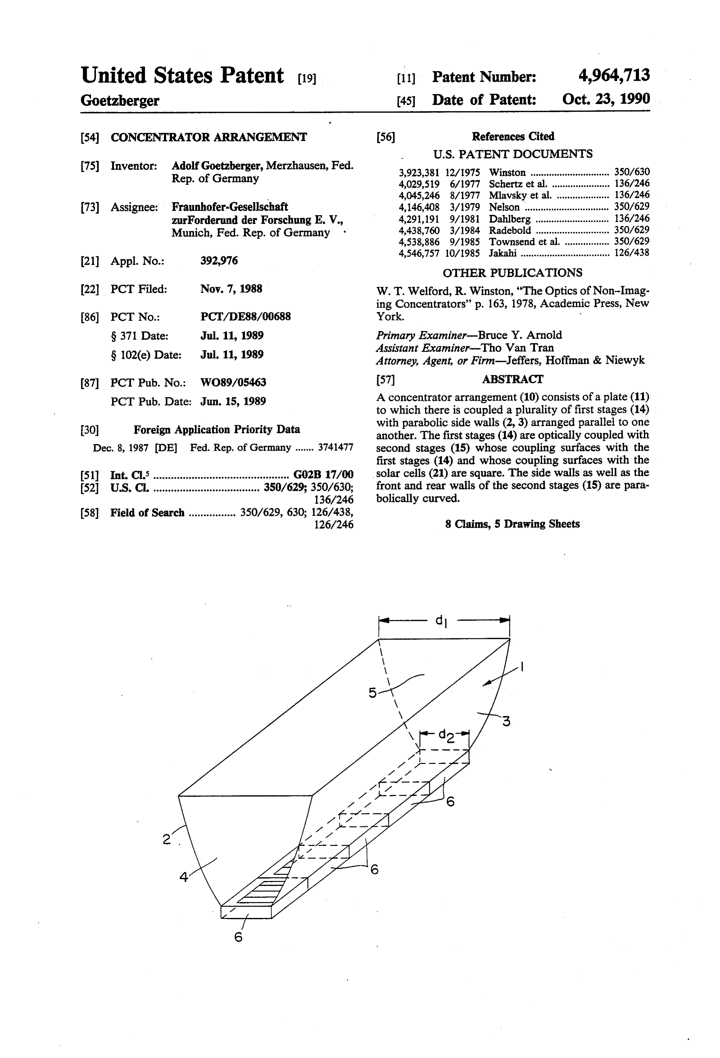
The static concentrator represented in FIG. 1 is
CONCENTRATOR ARRANGEMENT aligned in east-west direction, so that the face sides 4, 5 point to the east and west, respectively, and the side
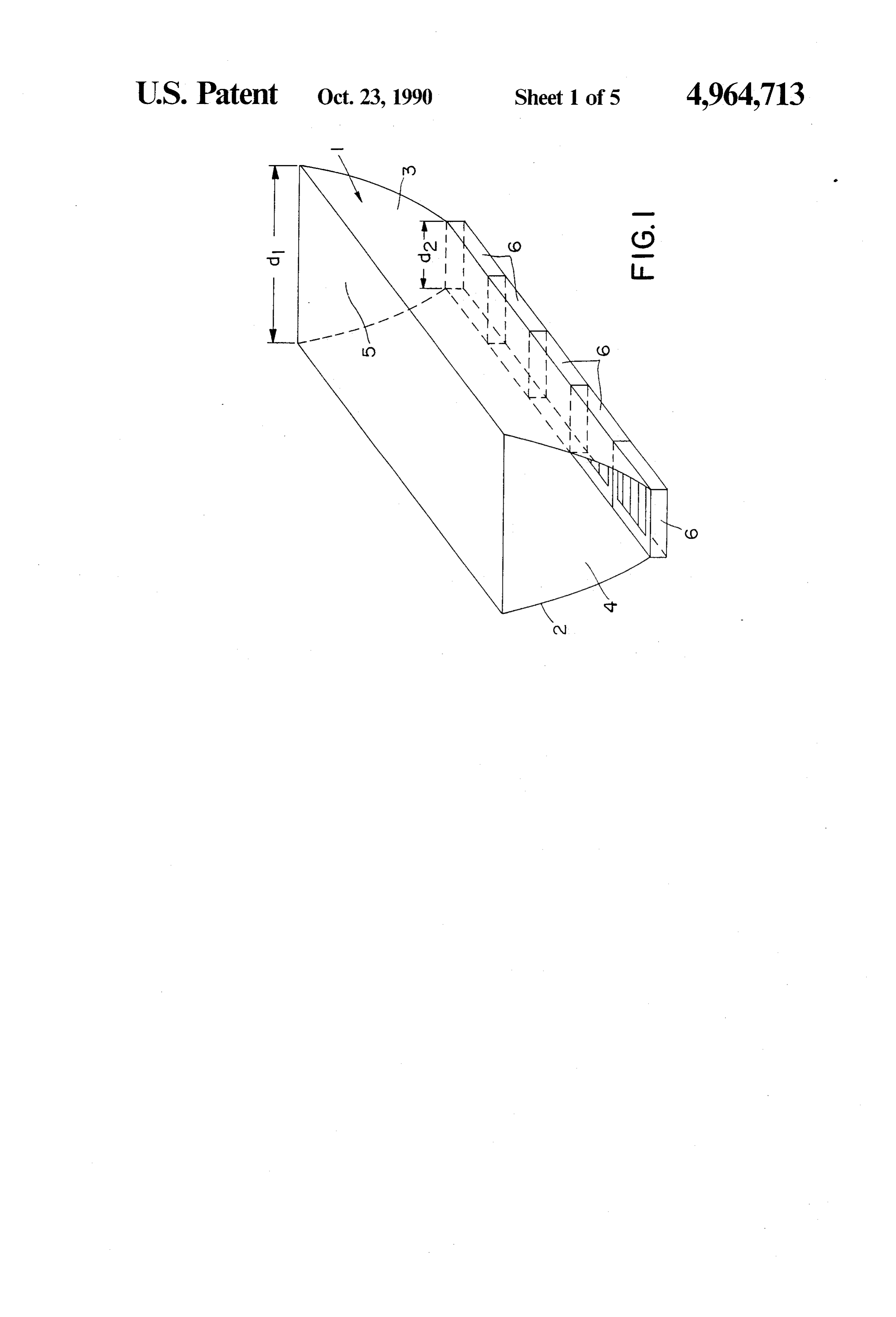
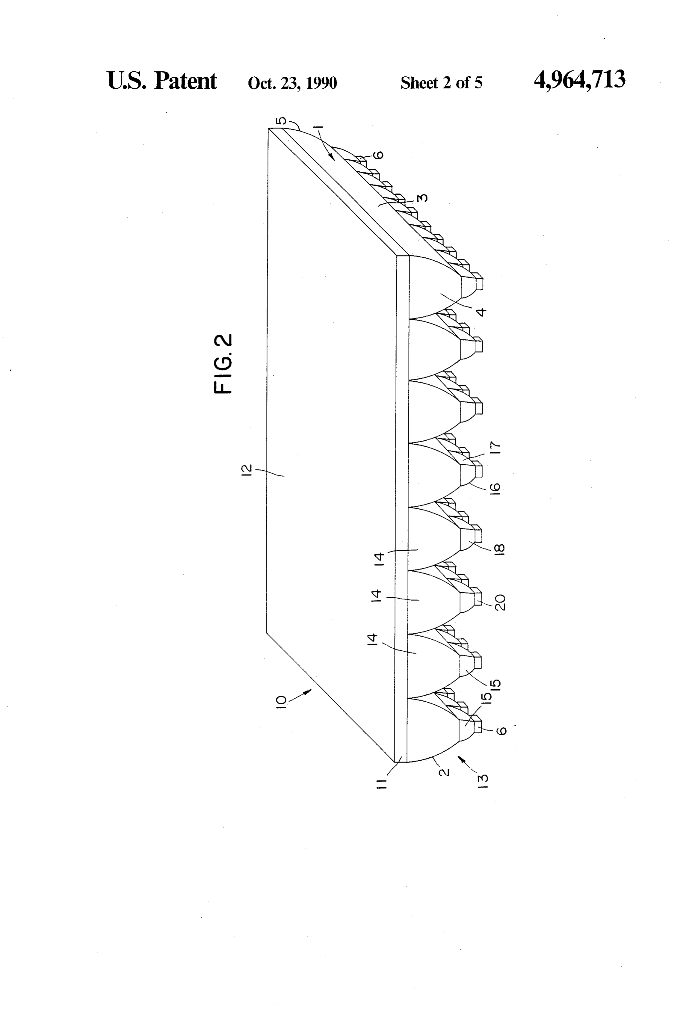
The invention relates to a concentrator arrangement walls 2, 3 point north and south, respectively. There the with a plurality of solar cells and with a plate made of 5 concentrator 1 is turned about its longitudinal axis run a transparent material with a refractive index of more ning parallel to the side walls 2 in order to achieve an than 1.45, which presents a flat upper side and an under alignment of the concentrator to the south with optimal side which is connected to trough-shaped non-imaging inclination. This inclination corresponds to the degree concentrator elements with parabolically curved side 10 of latitude of the place of erection. walls. The bottom of the static concentrator 1 represented Such concentrator arrangements are known from W. in FIG. 1 is occupied with several solar cells 6 which . T. Welford, R. Winston "The optics of non-imaging utilize the direct and diffuse solar light captured by the concentrators,' Academic Press, New York (1978) and static concentrator 1 through photovoltaic energy serve as static non-imaging concentrators, in contrast to 15 transformation. The concentrator 1 forms a static, non readjusted concentrators with optically imaging sys imaging concentrator of type CPC (Compound Para tems, which because of their small acceptance angle bolic Concentrator). Such a concentrator is limited in have to be aligned relatively accurately upon the sun, the concentration factor C= a1/a2 by the Liouville con but in return carry out a photovoltaic energy transfor dition mation without complicated mechanical readjusting 20 arrangements. 81 02 Underlying the invention is the problem of creating a a1 in Sin 2 = a n2 sin - -, concentrator arrangement of the type mentioned at the outset which is distinguished by a higher concentration in which ai is the entry aperture surface, a2 the exit factor. aperture surface, n1 the refractive index of the medium This problem is solved according to the invention by 25 in front of the concentrator, n2 the refractive index of the means that the concentrator elements have paraboli the medium inside the concentrator, 61 the aperture cally curved mirror surfaces facing to the sky. angle of the beams at the entry aperture and 62 the Advantageous formations and further developments aperture angle of the radiation at the exit aperture. of the invention are the object of subclaims. 30 In order to receive as much as possible direct solar In the following, examples of execution of the inven radiation, a static concentrator must have a large aper tion are described in detail with the aid of the drawing. ture angle which may be smaller in north-south direc FIG. 1 shows a concentrator of CPC type (com tion than in east-west direction. In north-south direction pound parabolic concentrator) of known construction the reception zone must extend, on the one hand, up to type; 35 the upper culmination point of the sun, and, on the other FIG. 2: a concentrator arrangement according to the hand, invention with a two-stage concentration, in perspec lectorsinto the vicinity of the southern horizon. In col or concentrators standing staggered one after tive; another the limitation can lie at-the lower culmination FIG. 3: a view of the concentrator arrangement in point of the sun. In the east-west direction, however, east or west direction;
FIG. 4: a side view of the concentrator arrangement the aperture angle must amount to 180. These condi tions led to the trough form of the static concentrator in north or south direction;
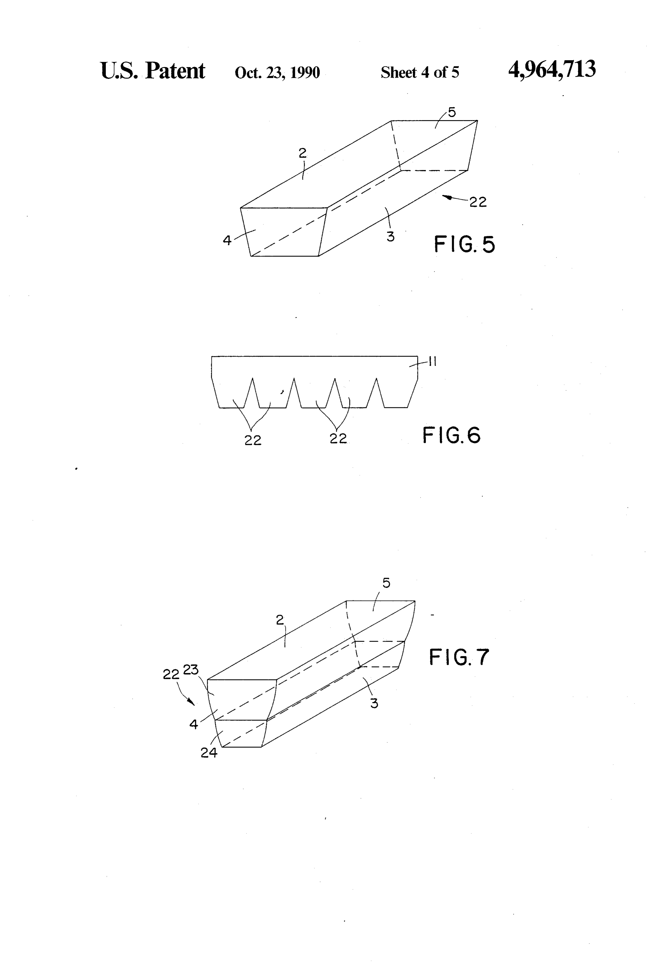
FIG. 5: a concentrator element for rectangular solar FIG. 1,one-dimensional with concentration represented in for which the Liouville condition reads:
cells;
FIG. 6: a concentrator arrangement with several 45 concentrator elements according to FIG. 5, which are d 81 02
joined with one another by a plate;
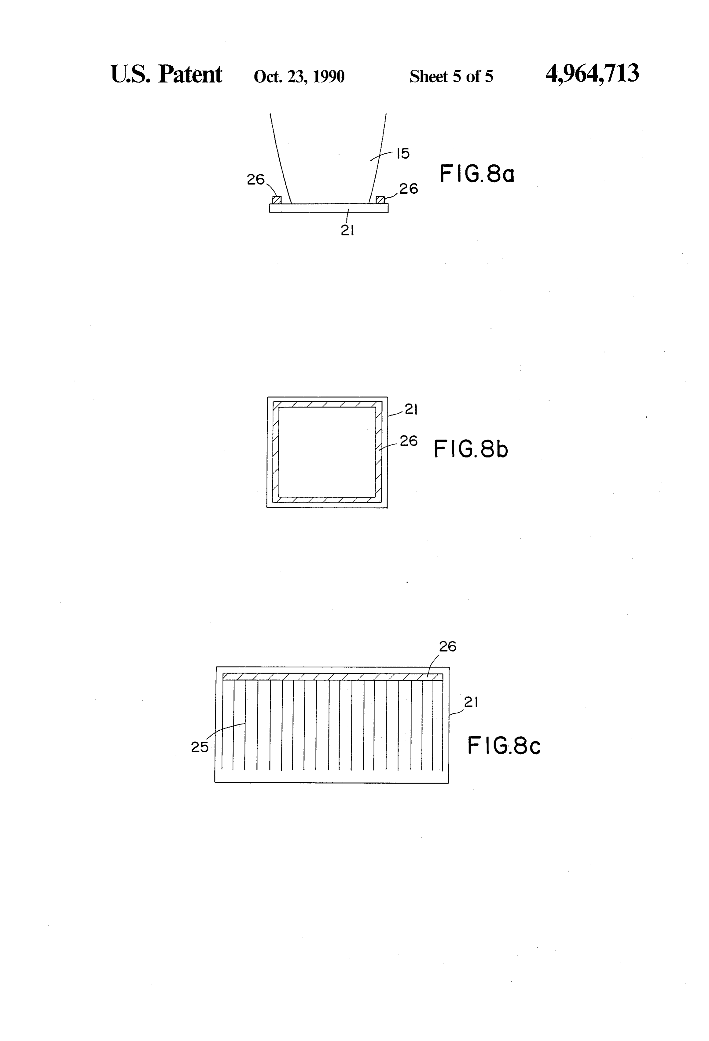
FIG. 7: a concentrator element for rectangular solar in which d1 and d2 signify the above-mentioned spacings cells with two successive media of different refractive index, and 50 of the side walls 2, 3 or the widths of the concentrator FIG. 8 various contact geometries for the arrange 1 at the entry aperture surface and of the exit aperture ment of the current-collecting contacts outside of the surface, illuminated surface of the solar cells. FIG. 2 shows a two-stage concentrator arrangement In FIG. 1 there is represented a static concentrator 1 10 according to the invention, which makes it possible of known construction type, which has the form of a 55 with retention of the aperture angle distribution to trough and permits a one-dimensional concentration. achieve a substantially higher static concentration. The static concentrator 1 has a parabolically curved left There, a two-stage concentration is carried out in a side wall 2 and a likewise parabolically curved right refracting medium.
side wall 3. The side walls 2, 3 have at their upper bor The two-stage concentrator arrangement 10 has at its ders a spacing d1 and approach one another at their 60 disposal a plate 11 of transparent material with a refrac lower borders to a spacing d2. In general, the side walls tive index n that is greater than 1.45. The plate 11 is flat 2, 3 are mirror-coated. The space between the side walls on the upper side 12 facing the incident radiation and on 2, 3 can be filled with glass or plastic with a refractive the side lying opposite the upper side 12 it is connected index n2 = 1.5, with which it is possible to achieve con optically and mechanically with a structure 13 for the centration factors of 2 to 2.2, or the space can also be 65 non-imaging concentration of light. The structure 13 formed without a refracting medium (N2= 1) between brings about a two-stage concentration of the light in the side walls 2, in which case there can only be linear-unidimensional first stages 14 and two-dimen achieved concentration factors of 1.4 to 1.5. sional second stages 15.
Page 8
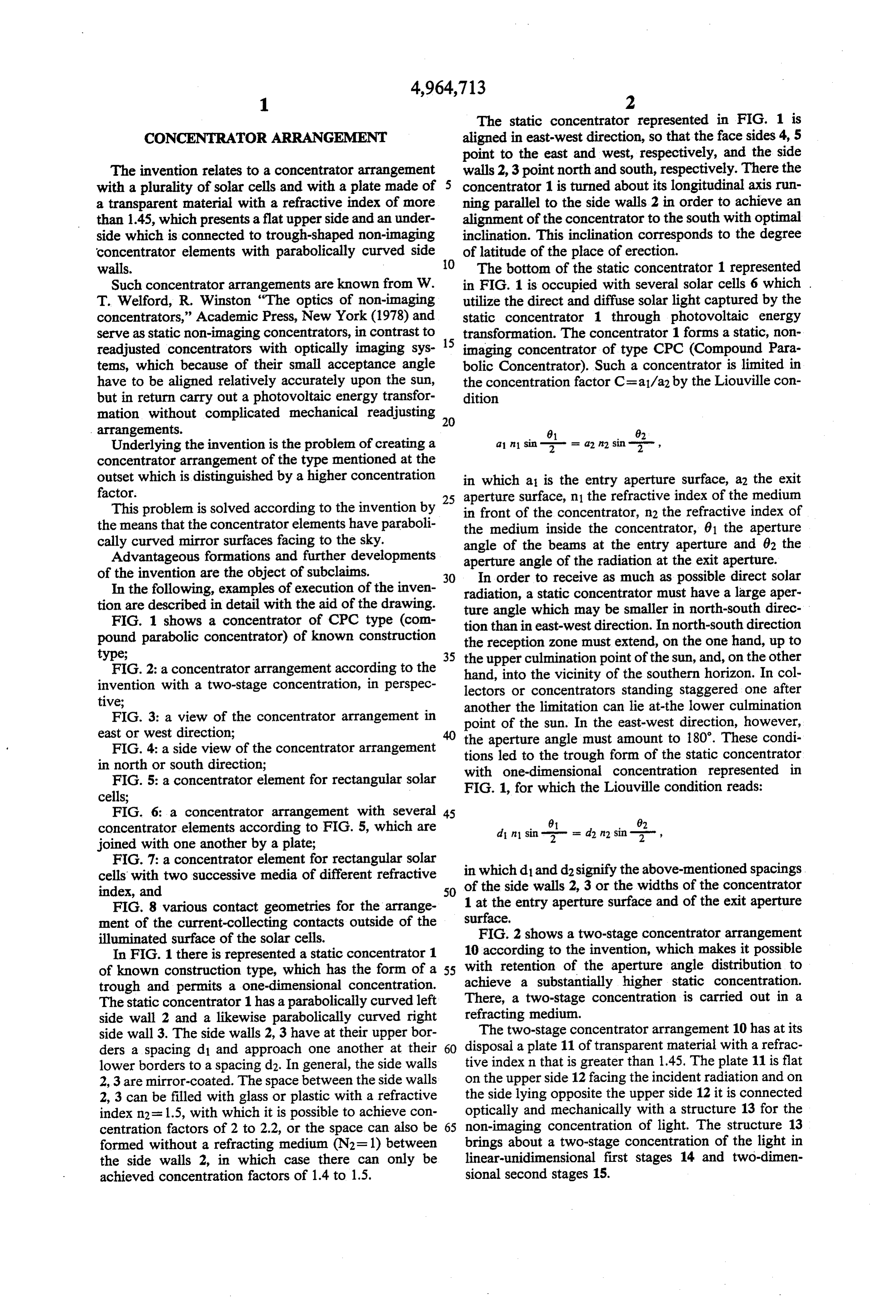
The first stages 14 have the form represented in FIG.
1 of a trough made of glass or plastic. To the exit aper - - -- - ture surfaces of the first stages there are optically and d2 sin 01/2 mechanically coupled in each case a large number of second stages 15, which present also parabolically bent one perceives that a factor n is gained. side walls 16 and 17 represented in FIG. 3 as well as The second stages 15 can consist of a transparent parabolic front walls 18 and rear walls 19 recognizable material with a refractive index n2 which is greater than in FIG. 4. The lower borders of the side walls 16, 17 and the refractive index n1 of the transparent material of the of the front walls 18 as well as of the rear walls 19 end 10 first stages 14. This is significant because for this little in each case on a bottom surface 20, which is optically material is consumed and materials with a relatively coupled with a solar cell 21. high refractive index are mostly expensive. In this case As is yielded from FIGS. 2 to 4, the first stages 14 the condition for the second stages 15 is have rectangular entry apertures and rectangular exit apertures, while the touching second stages 15 present 15 square entry and exit apertures. The second stages 15, A1 therefore, are not exactly radially symmetrical, which 42 = n.
leads to a slight loss in concentration. This, however, is expedient, since, on the one hand, the aperture surface can be filled only with square or rectangular structures, 20 as The
full concentration is then n22/(sin 0/2), therefore the entire concentrator arrangement 10 consisted of and, on the other hand, the solar cells 21 are square. the material with the refractive index n2. The Liouville condition is optimally exhausted when In the concentrator arrangement 10 described only 6= 180". In the linear trough concentrator with a re the relative dimensions enter into the concentration. fracting medium whose refractive index is greater than 25 For this reason very flat structures can be realized with 1 this is achieved only in the north-south direction, but relatively low consumption of material. This requires not in the east-west direction. According to the law of small solar cells 21 which must be correspondingly refraction in air horizontal beams after entry into the accurately positioned. This is possible with the aid of medium have a divergence 0", which is given by the processes developed in semiconductor technology. 30 In the following table there are cited quantitative sin 6/2=1/n. examples for 0/2=23.5".
By a two-dimensional concentration this divergence can be increased to 90'. In the two-stage concentrator arrangement 10 according to the invention this is Two-stage Linear trough concentrator in s 1.5 Cmax = 3.76
achieved by the means that in the linear first stages 14 35 Two-stage concentrator n = 1.5; n2 = 1.8 Cmax = 8.13 the north-south beams are brought to the same diver Two-stage concentrator n = 1.5; n2 = 2 Cmax = 10.03 gence as the east-west beams (by analysis into vertical components this observation holds also for all obliquely As compared with the execution according to FIG. 1 incident rays). with a concentration factor of 3.76 there are achieved The dimensions d1 and d2 of the first linear parabolic 40 with the concentrator arrangement 10, depending on stage 14 are give, therefore, by . the refractive index of the first stages 14 and second
stages 15, clearly higher concentration factors between
The aperture angle 61 of the first stages 14 is chosen in which 0 is the north-south entry angle determined by 45 in such a way that on alignment of the concentrator the above-indicated conditions. There is yielded, there arrangement 10 to the south with optimal inclination fore, the location of the sun at its highest altitude still falls in
the acceptance range, and the other limit of the aperture angle ps Since the radiation is now axially symmetrical, it is the sun.
50 contains at least the minimal culmination point of two-dimensionally further concentrated in the second stages 14The is linear concentration factor C of the first chosen in such a way aperture angle of the stages 15 to 0 = 180'. rays projected onto the north-south direction fulfills on There holds the following: the exit surface the condition C1 = 1/(sin 61/2). A n sin 8/2= A2 sin T/ 55 In a concentrator arrangement 10 that consists of a homogeneous medium with the refractive index n, the concentration factor C2 of the second two-dimensional stage 15 is chosen in such a way that there holds C2 = n2.
It is especially advantageous if the first stages 14 are made of a material with a refractive index n1 and the where A and A2 are the entry and exit aperture sur second stages 15 are made of another material with a faces(areas) allocated to the second stages 15. refractive index n2 that is greater than the refractive index n1. In such a case it is possible to achieve the n2 result that the concentration of the second stages is
In one example of execution of the invention the plate
If one compares this with the conventional one-stage 11 is rectangular and has a flat front side. On the back concentration of there are present many juxtaposed linear structures of
Page 9
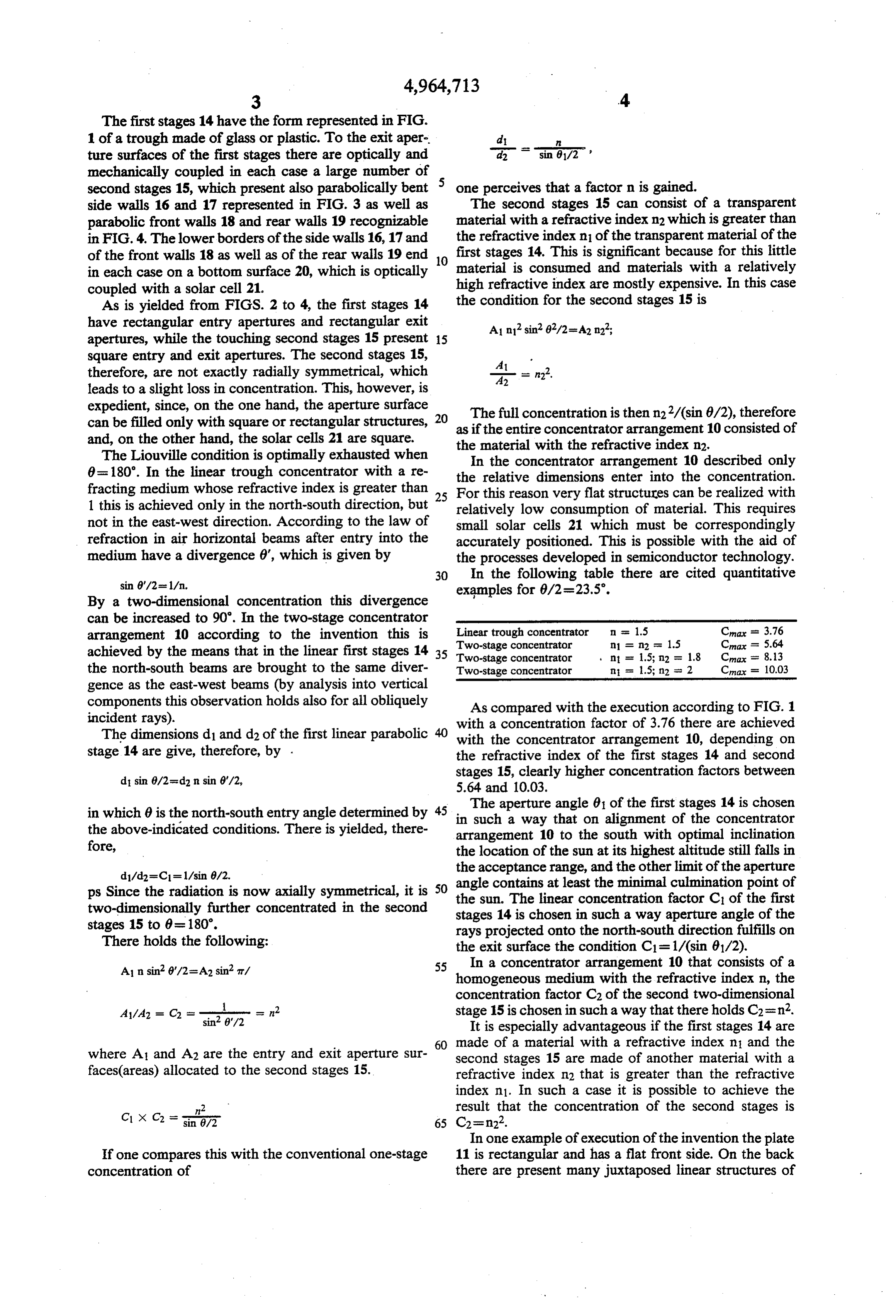
the first stage 14 on the exit openings of which there are on the entry aperture of the concentrator 22, at the present touching elements of the second stages 15. transition to the second material 24 and at the exit aper The plate 11, the first stages 14 and the second stages ture.
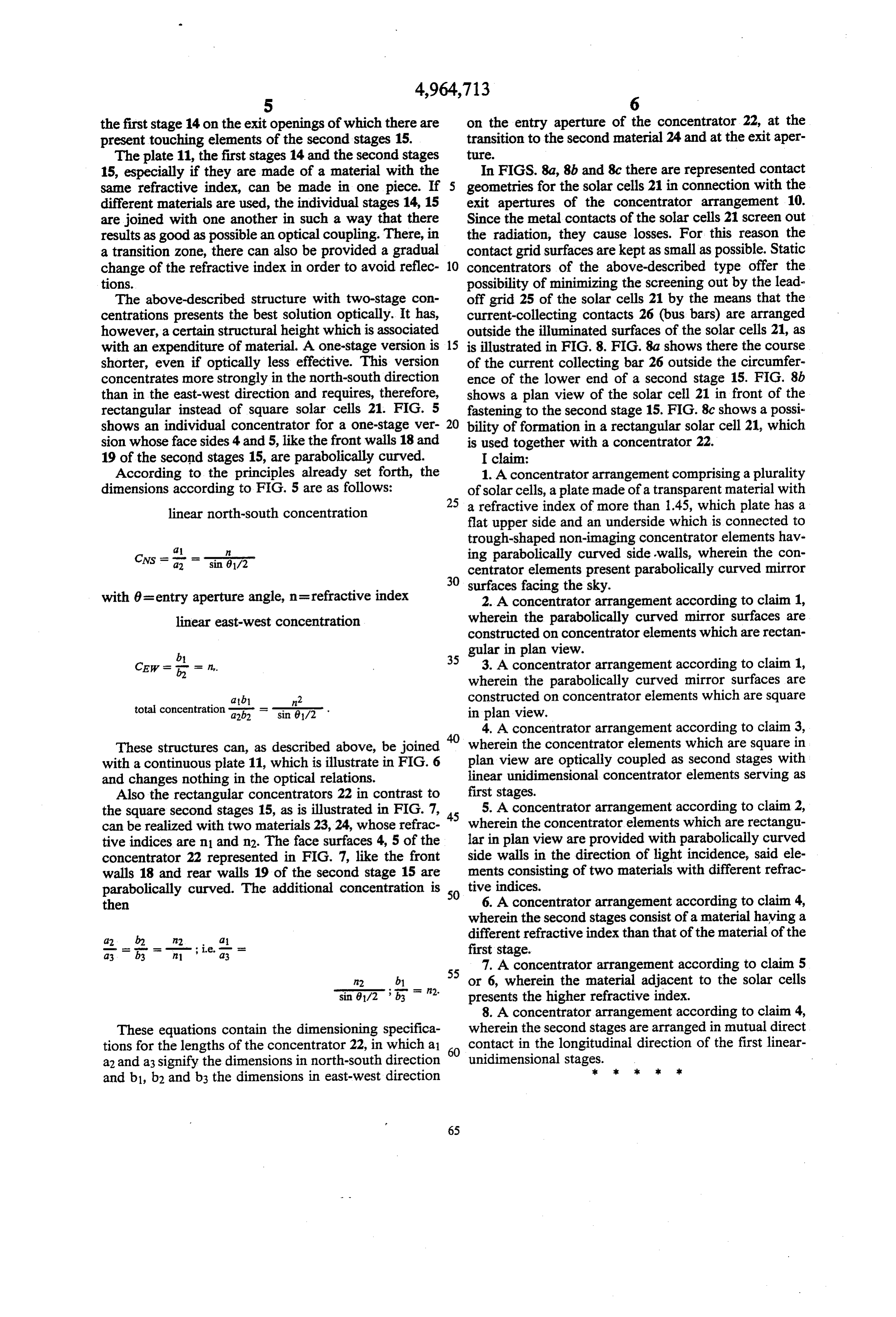
15, especially if they are made of a material with the In FIGS. 8a, 8b and 8c there are represented contact same refractive index, can be made in one piece. If 5 geometries for the solar cells 21 in connection with the different materials are used, the individual stages 14, 15 exit apertures of the concentrator arrangement 10. are joined with one another in such a way that there Since the metal contacts of the solar cells 21 screen out results as good as possible an optical coupling. There, in the radiation, they cause losses. For this reason the a transition zone, there can also be provided a gradual contact grid surfaces are kept as small as possible. Static change of the refractive index in order to avoid reflec 10 concentrators of the above-described type offer the tions. possibility of minimizing the screening out by the lead The above-described structure with two-stage con off grid 25 of the solar cells 21 by the means that the centrations presents the best solution optically. It has, current-collecting contacts 26 (bus bars) are arranged however, a certain structural height which is associated outside the illuminated surfaces of the solar cells 21, as with an expenditure of material. A one-stage version is 15 is illustrated in FIG. 8. FIG. 8a shows there the course shorter, even if optically less effective. This version of the current collecting bar 26 outside the circumfer concentrates more strongly in the north-south direction ence of the lower end of a second stage 15. FIG. 8b than in the east-west direction and requires, therefore, shows a plan view of the solar cell 21 in front of the rectangular instead of square solar cells 21. FIG. 5 fastening to the second stage 15. FIG. 8c shows a possi shows an individual concentrator for a one-stage ver 20 bility of formation in a rectangular solar cell 21, which sion whose face sides 4 and 5, like the front walls 18 and is used together with a concentrator 22. 19 of the second stages 15, are parabolically curved. I claim:
According to the principles already set forth, the 1. A concentrator arrangement comprising a plurality dimensions according to FIG. 5 are as follows: of solar cells, a plate made of a transparent material with 25 a refractive index of more than 1.45, which plate has a linear north-south concentration flat upper side and an underside which is connected to trough-shaped non-imaging concentrator elements hav
Cws
-a- ing parabolically curved sidewalls, wherein the con centrator elements present parabolically curved mirror 30 surfaces facing the sky.
with 0=entry aperture angle, n=refractive index 2. A concentrator arrangement according to claim 1, linear east-west concentration wherein the parabolically curved mirror surfaces are constructed on concentrator elements which are rectan gular in plan view.
35 3. A concentrator arrangement according to claim 1, wherein the parabolically curved mirror surfaces are tal at b1 n2 constructed on concentrator elements which are square to concentration a2b2 - sin 0. M2 in plan view.
4. A concentrator arrangement according to claim 3,
These structures can, as described above, be joined wherein the concentrator elements which are square in with a continuous plate 11, which is illustrate in FIG. 6 plan view are optically coupled as second stages with and changes nothing in the optical relations. linear unidimensional concentrator elements serving as Also the rectangular concentrators 22 in contrast to first stages.
the square second stages 15, as is illustrated in FIG. 7, 45 5. A concentrator arrangement according to claim 2, can be realized with two materials 23, 24, whose refrac wherein the concentrator elements which are rectangu tive indices are n1 and n2. The face surfaces 4, 5 of the lar in plan view are provided with parabolically curved concentrator 22 represented in FIG. 7, like the front side walls in the direction of light incidence, said ele walls 18 and rear walls 19 of the second stage 15 are ments consisting of two materials with different refrac parabolically curved. The additional concentration is 50 tive indices.
then 6. A concentrator arrangement according to claim 4, wherein the second stages consist of a material having a different refractive index than that of the material of the first stage.
7. A concentrator arrangement according to claim 5 n2 b or 6, wherein the material adjacent to the solar cells sin 9/2 ; B = n2. presents the higher refractive index.
8. A concentrator arrangement according to claim 4,
These equations contain the dimensioning specifica wherein the second stages are arranged in mutual direct tions for the lengths of the concentrator 22, in which a 60 contact in the longitudinal direction of the first linear a2 and a 3 signify the dimensions in north-south direction unidimensional stages.k sk sk xk k and b1, b2 and b3 the dimensions in east-west direction
Provenance
- Collection
- Cited prior art
- Original PDF
- patentimages.storage.googleapis.com →
- Filed
- 1988-11-07
- Pages
- 9
- Method
- pdftotext (the PDF's own text layer) + pdftoppm 300dpi page scans
- Source
- Google Patents bibliographic record
- Granted
- 1990-10-23
- Inventors
- Adolf Goetzberger; Fraunhofer Gesellschaft zur Foerderung der Angewandten Forschung eV
- Transcribed from
- patentimages.storage.googleapis.com →