patent · US4728981
Imaging lens array and optical print head
1 March 1988
Page 1 — bibliographic record
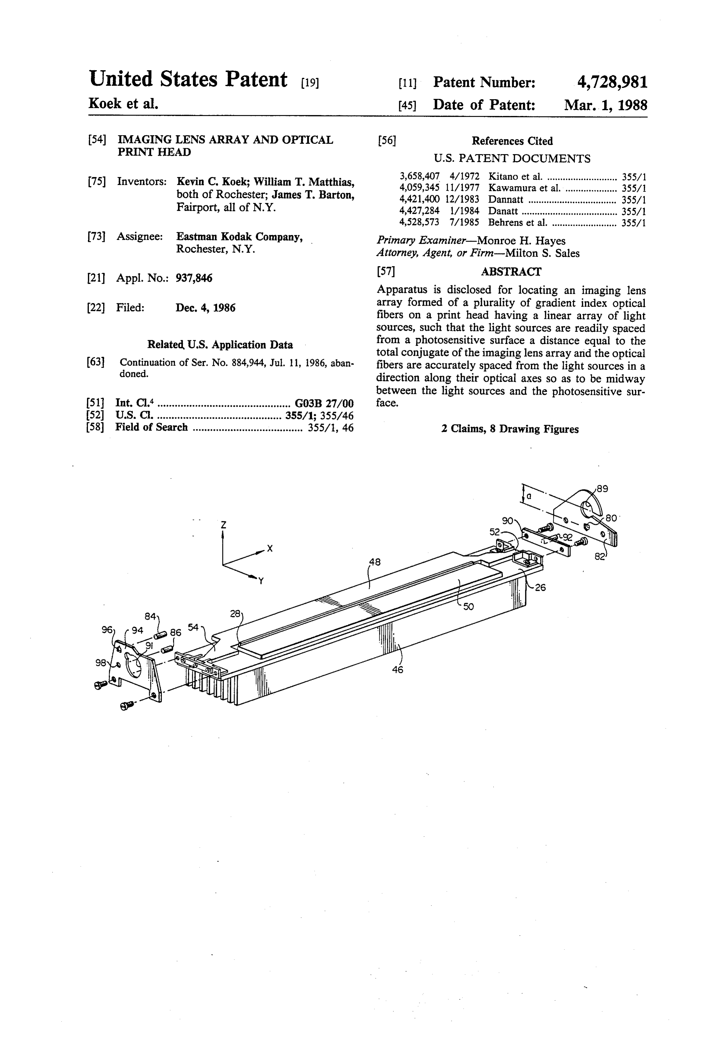
United States Patent (19) 11 Patent Number: 4,728,981 Koek et al. (45) Date of Patent: Mar. 1, 1988 (54) MAGING LENS ARRAY AND OPTICAL (56) References Cited
PRINT HEAD
(75) Inventors: Kevin C. Koek; William T. Matthias, 3,658,407 4/1972 Kitano et al. ......
both of Rochester; James T. Barton, 4,421,400 12/1983 Dannatt .................................. 355/1 Fairport, all of N.Y. 4,427,284 1/1984 Danatt ..................................... 355/1 4,528,573 7/1985 Behrens et al. ......................... 355/1 73 Assignee: Eastman Kodak Company, Primary Examiner-Monroe H. Hayes Rochester, N.Y. Attorney, Agent, or Firm-Milton S. Sales 21) Appl. No.: 937,846 (57) ABSTRACT Apparatus is disclosed for locating an imaging lens 22) Filed: Dec. 4, 1986 array formed of a plurality of gradient index optical fibers on a print head having a linear array of light sources, such that the light sources are readily spaced
Related U.S. Application Data from a photosensitive surface a distance equal to the total conjugate of the imaging lens array and the optical (63) Continuation of Ser. No. 384,944, Jul. 11, 1986, aban fibers are accurately spaced from the light sources in a doned. direction along their optical axes so as to be midway between the light sources and the photosensitive sur 51 Int. Cl............................................... G03B 27/00 face.
(52) U.S. C. ........................................... 355/1; 355/46 58) Field of Search ...................................... 355/1, 46 2 Claims, 8 Drawing Figures
Page 2
Drawing sheet — no readable text.
Page 3
Drawing sheet — no readable text.
Page 4
Drawing sheet — no readable text.
Page 5
Drawing sheet — no readable text.
Page 6
and LF vary considerably between manufacturers, and
IMAGING LENS ARRAY AND OFTICAL PRINT even between lenses of the same manufacturer. HEAD It is, therefore, an object of the present invention to provide means for locating an imaging lens array on a
CROSS REFERENCE TO RELATED 5 print head and for locating the print head relative to APPLICATION photosensitive means at the image plane in a way which This application is a continuation application of U.S. allows for convenient and accurate compensation for Ser. No. 884,944, filed on July 11, 1986, now aban variations in lens dimensions. Several significant bene doned, in the name of Kevin C. Koek et al. fits are provided by the locating means to be described. 10 These benefits stem from the precise locational and
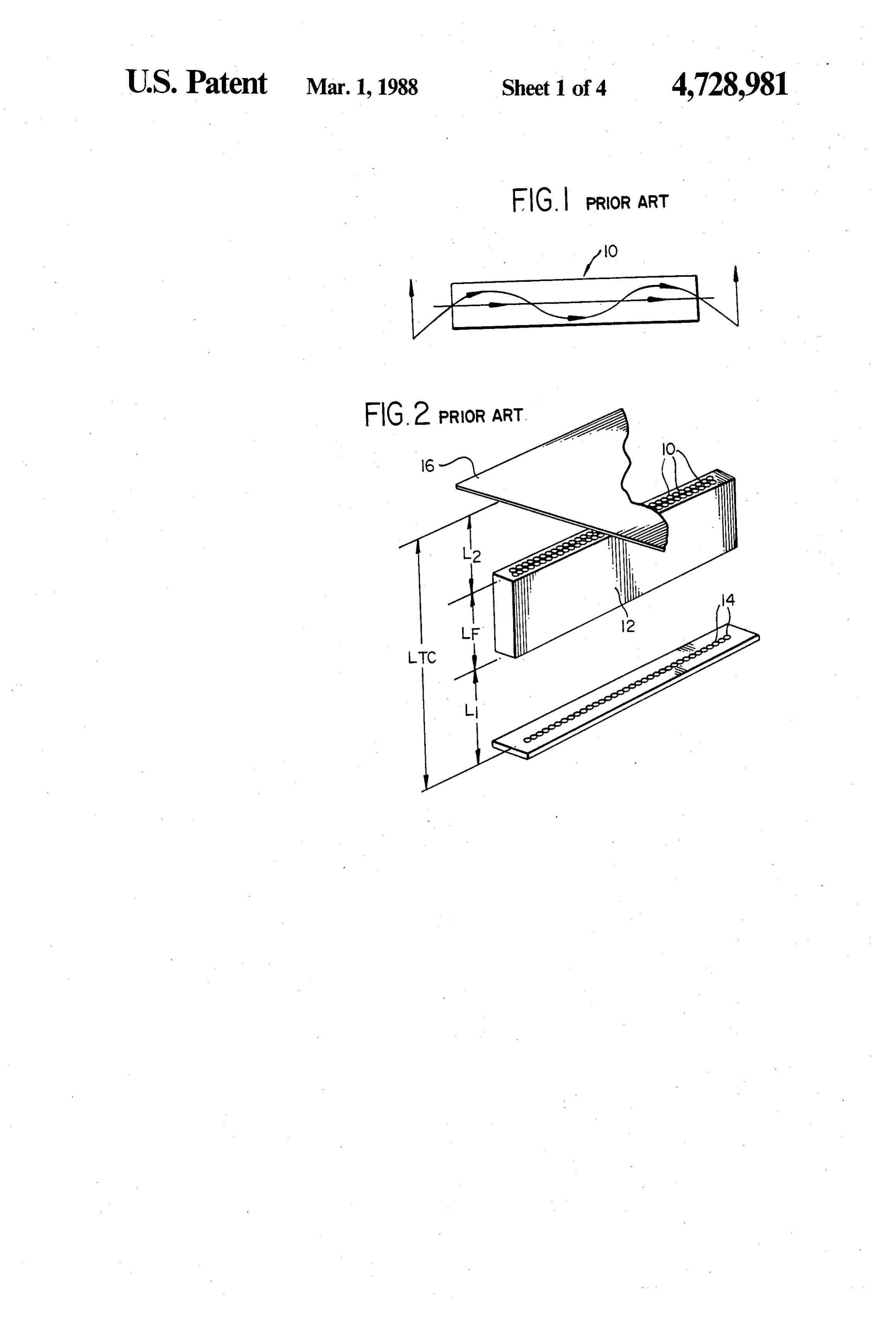
BACKGROUND OF THE INVENTION adjustment capabilities built into the locating means, 1. Field of the Invention and include (1) low parts cost due to relaxed tolerances, The present invention relates to optical print heads (2) elimination in most instances of adjustments of the and to means for transmitting light emitted from the 15 locating means at the machine level, both in final in print heads to a photosensitive surface, and more partic plant assembly and in the field because such adjustments ularly to means for accurately spacing (1) the print head have been affected during sub-assembly of the lens from the photosensitive surface and (2) the transmitting array to the print head, and (3) ability to perform direct, means from the print head to maintain high resolution in-the-field replacement due to the interchangeability of and good exposure uniformity. 20 print head and lens array sub-assemblies. 2. Description of the Prior Art SUMMARY OF THE INVENTION High speed optical printing devices used in data pro cessing systems are intended for converting electric In accordance with the present invention, novel ap input signals into printed form, and include photosensi paratus is provided for locating an imaging lens array tive means and light sources such as linear arrays of 25 formed of a plurality of gradient index optical fibers on light emitting diodes (LED's), photodiodes, or similar a print head having a linear array of light sources, such devices. Light from a source is often transmitted to the that (1) the light sources are readily spaced from a pho photosensitive means via a plurality of gradient index tosensitive surface a distance equal to the total conju optical fibers forming an imaging lens array. Such imag gate of the imaging lens array, and (2) the optical fibers ing lens arrays are commercially available as SELFOC 30 are accurately spaced from the light sources in a direc (a trademark of Nippon Sheet Glass Co., Ltd.) lenses in tion along their optical axes so as to be midway between a staggered, two-row bundle of optical fibers as de the light sources and the photosensitive surface. scribed in U.S. Pat. No. 3,658,407, patented on April 25, In a preferred embodiment of the present invention, 1972. Reference may be made to that patent for details locating means are provided for removably supporting of the lens arrays. - 35 the print head relative to the photosensitive surface A gradient index optical fiber 10 is illustrated in FIG. such that the light sources of the print head are spaced 1. The refractive index distribution of the optical fiber from the photosensitive surface by the total conjugate varies parabolically outwards from the longitudinal axis of the optical fibers. Mounting means support the lens of the optical fiber towards the peripheral portion array to the print head so as to center the lens array thereof. between the light sources and the photosensitive sur FIG. 2 shows an imaging lens array 12 formed of a face.
staggered, two-row bundle of optical fibers 10. If the The invention, and its objects and advantages, will distances L1 and L2 are properly selected and equal, become more apparent in the detailed description of the then there is obtained an erect image at a magnification preferred embodiment presented below. of one of an object. Distance LTC represents the total 45 BRIEF DESCRIPTION OF THE DRAWINGS conjugate of the lens (i.e., the distance between the object and image planes). Accordingly: In the detailed description of the preferred embodi ment of the invention presented below, reference is
Li=L-2, made to the accompanying drawings in which: 50 FIG. 1 is a representation of an optical fiber in accor and dance with the prior art and wherein the geometry of the fiber is illustrated;
LTC= LF--L--L2 FIG. 2 is a perspective view of an imaging lens array formed by a staggered, two-row bundle of optical fibers
Where LF is the length of optical fibers 10 of imaging 55 as shown in FIG. 1, and also shows a print head with an lens array 12. LED array at the object plane and photosensitive Imaging lens arrays such as shown in FIG. 2 have means at the image plane;
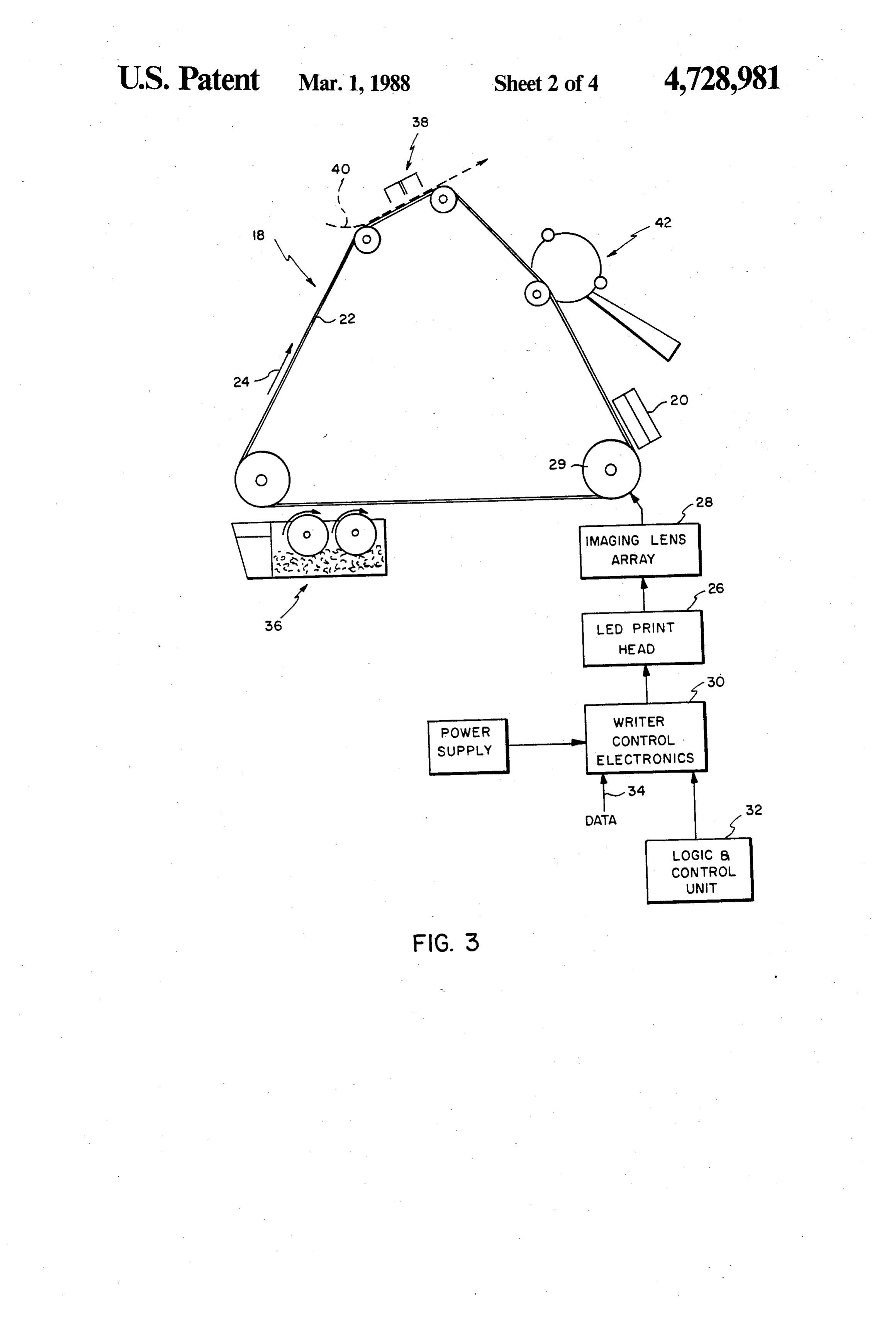
been proposed for transmitting light between an array FIG. 3 is a schematic vertical section of an electro of LED's 14 and photosensitive means such as a photo photographic apparatus including the image lens array conductive member 16. For optimum resolution, dimen and print head of FIG. 2;
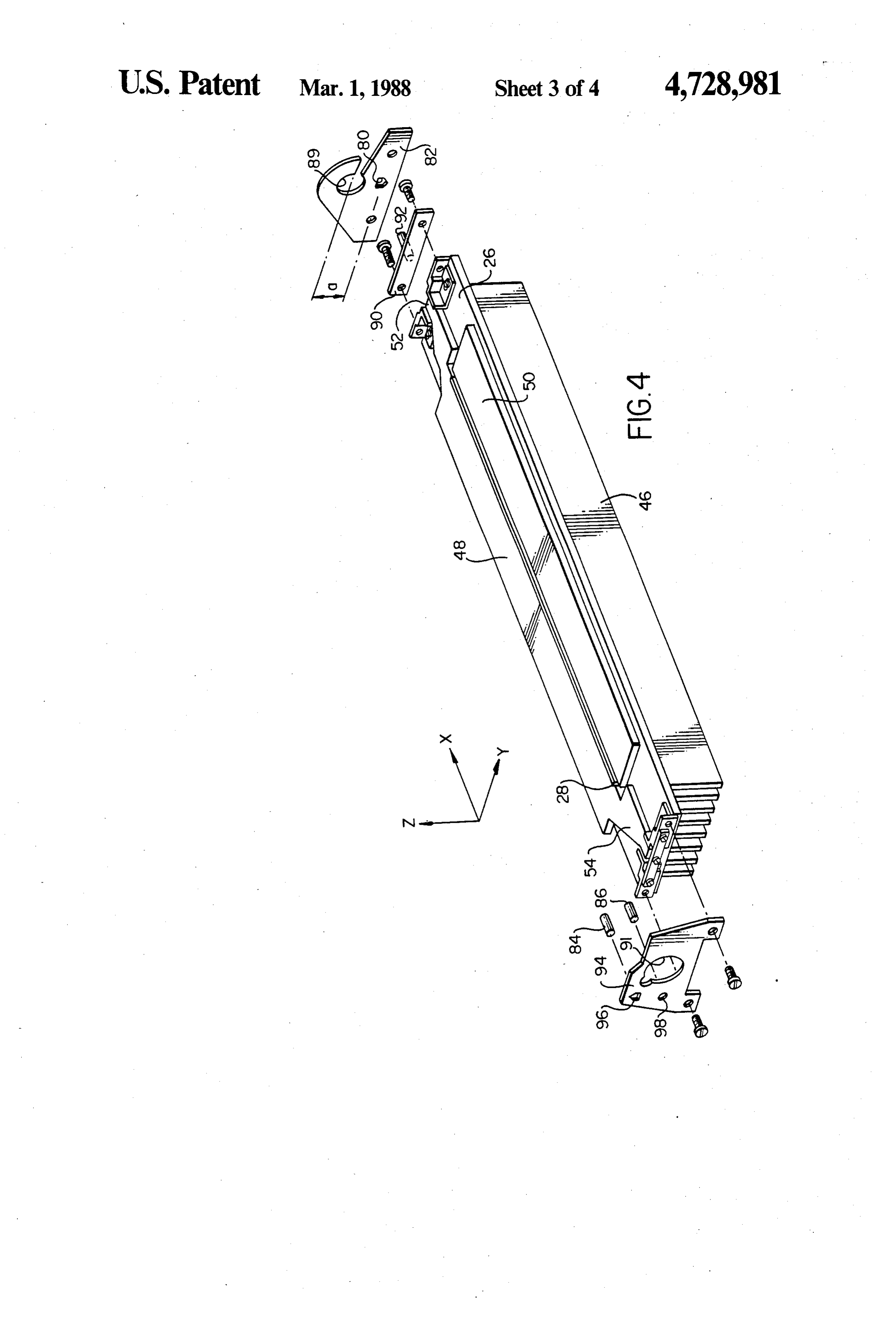
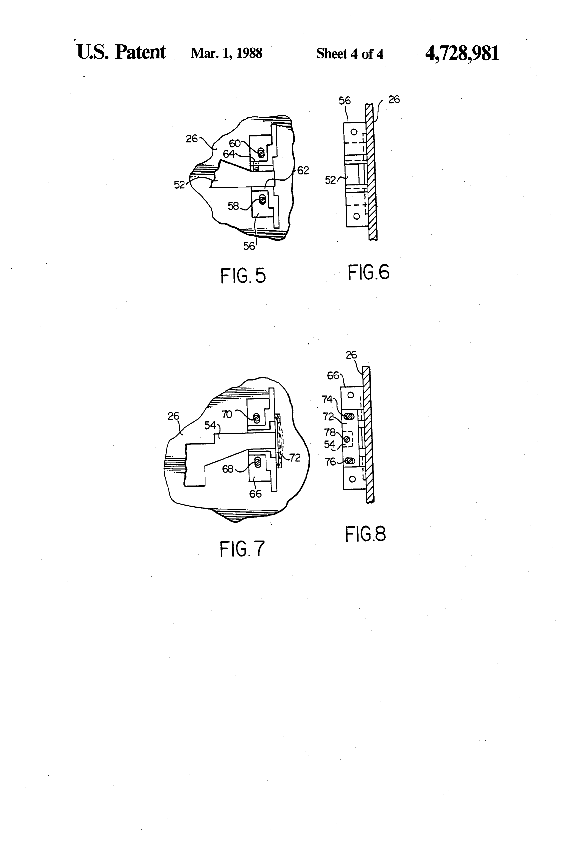
sions LTC, Li, and L2 must be accurately set and main FIG. 4 is a perspective view of a print head and imag tained. In the design of prior art devices such as shown ing lens array sub-assembly with locating means in ac in U.S. Pat. No. 4,147,412, it is assumed that the total cordance with the present invention; conjugate LTC does not vary from lens to lens and that, FIGS. 5 and 6 are top and side views, respectively, as such, the spacing between the object plane and the 65 showing details of a portion of the locating means; and image plane can be fixed at the total conjugate distance.
While this approximation is adequate for low resolution showing 7details
FIGS. and 8 are top and side views, respectively, of another portion of the locating applications, in fact however, the lens parameters LTC eaS.
Page 7
DETAILED DESCRIPTION OF THE
mounted on print head 26 by a pair of screws 58 and 60
PREFERRED EMBODIMENT
and elongated holes in the block through which the screws pass. After imaging lens array 28 has been prop
The present description will be directed in particular erly aligned laterally with the LED array (the Y-direc to elements forming part of, or cooperating more di tion of FIG. 4), block 56 is slid (the screws being loose) rectly with, apparatus in accordance with the present until an upstanding wing 62 abuts arm 52 of stiffener 48. invention. It is to be understood that elements, compo Screws 58 and 60 are tightened. When the imaging lens nents, and/or sub-components not specifically shown or array is properly spaced from the LED array (the Z described may take various forms well known to those direction of FIG. 4) by a distance L1 of FIG. 2, a set skilled in the art. O screw 64 is tightened to totally constrain arm 52 relative To assist in understanding the present invention, an to the print head.
electrophotographic copier/printer in which the inven The attachment means for arm 54 can best be seen in tion may be used will be briefly described. It will be FIGS. 7 and 8 (as well as FIG. 4. The coefficient of understood, however, that the apparatus of the present thermal expansion of the imaging lens array and stiffen invention can be used in other types of apparatus. 15 ers may differ from that of the print head, and must be Referring to FIG. 3, electrophotographic apparatus accounted for in the design of the mounting means. The generally designated 18 includes a charging station 20 attachment of arm 54 is not the same as that of arm 52 for applying a uniform charge to photosensitive means and provides for such thermal expansion. After imaging such as a photoconductor 22. The photoconductor illus lens array 28 has been properly aligned with and spaced trated is an endless belt trained about a plurality of 20 from the LED array, as described above, final attach rollers and driven in the direction of an arrow 24. Light ment of arm 54 can be effected. An interface block 66 is from selected LED's of a print head 26 is transmitted by slidably mounted in the Y-direction on print head 26 by an imaging lens array 28 onto the surface of photocon a pair of screws 68 and 70 which pass through respec ductor 22 as the photoconductor passes over a roller 29. tive elongated holes in block 66. A flexible steel plate 72 The light striking the charged photoconductor selec 25 is mounted at its ends to block 66 by a pair of screws 74 tively dissipates portions of the charge to form an elec and 76 which also pass through elongated holes to per trostatic latent image on the photoconductor. Selection mit vertical (Z-direction) movement of the plate rela of the specific LED's of the print head which are acti tive to the interface block.
vated at any given time is by means of writer control During assembly, interface block 66 and plate 72 electronics 30, a logic and control unit 32, and the data 30 thereon are moved relative to arm 54 until a screw hole entering along line 34. in the plate aligns with a predrilled and tapped hole in A magnetic brush development station 36 transfers the end of arm 54. A screw 78 is inserted into the tapped toner particles to the photoconductor for developing hole and screws 68, 70, 74, 76 and 78 are tightened to the latent image. The resulting toned image then travels secure the sub-assembly elements such that movement to a transfer and detack station 38 where the image is 35 of imaging lens array 28 in directions along its optical transferred to a copy sheet fed from a supply, not axis (Z-direction) and lateral to the LED array (Yshown, along path 40. After the photoconductor passes direction) is inhibited, while thermal expansion and through transfer and detack, it is cleaned at station 42 contraction of the imaging lens array and stiffeners and is available for another cycle of operation. along their lengths (X-direction) at a rate different than Referring to FIG. 4, a sub-assembly 44 includes the expansion of the print head is permitted. print head 26 and imaging lens array 28, both of which By the apparatus described, mounting means are pro are schematically shown in FIG. 3. The print head per vided for the imaging lens to maintain critical spacing se is a conventional, commercially-available unit with a between the print head LED array and the imaging lens linear array of LED's, a transparent faceplate covering array equal to distance L2. Critical adjustments can be the LED's, and heat-conducting cooling vanes 46. In 45 easily and rapidly made during assembly without the aging lens array 28 includes a staggered, two-row bun need for high precision parts. However, for optimum die of gradient index optical fibers disposed above the resolution and exposure uniformity, print head sub LED array of the print head. The ends of the optical assembly 44 must be mounted on electrophotographic fibers are accurately spaced in a Z-direction (along the apparatus 18 such that the LED array is spaced from optical axes of the fibers) from the LED's by a distance 50 the surface of photoconductor 22 by a distance LTC L1 as shown in FIG. 2 as well as being accurately posi equal to the total conjugate of imaging lens array 28, tioned in a Y-direction (lateral to the LED array) so as and the imaging lens array itself must be spaced by to align with the LED's along the length of the print distance L2 from the photoconductor. To that end, head. The lens array is preferably longer than the LED adjustable mounting means have been provided, array so that the position of the imaging lens array along 55 whereby the distance between the LED array of print the X-direction (along the length of the LED array) is head 26 and the surface of photoconductor 22 can be not as critical. adjusted to match the total conjugate distance LTC of Commercially available imaging lens arrays of the the specific imaging lens array attached to the print typed discussed herein are somewhat flexible and tend head.
to bend. It will be appreciated that very little bending 60 Three locating structures are provided on the electro would be needed to cause significant defocusing of the graphic apparatus. The locating structures include a image of the LED's on the photoconductor. Accord V-shaped opening 80 in a plate 82, and a pair of pins 84 ingly, imaging lens array 28 has been bonded between and 86 which extend from a mechanism plate (not two stiffeners 48 and 50. Stiffener 48 has a pair of arms shown) in the electrophotographic apparatus. Opening 52 and 54 for attaching the stiffener (and thereby the 65 80 and pins 84 and 86 are fixed in the electrographic imaging lens) to the print head. apparatus mainframe at accurately known positions Details of the attachment means for arm 52 are better relative to the bearings of roller 29. This spacial rela seen in FIGS. 5 and 6. An interface block 56 is slidably tionship is intended to be substantially invariant from
Page 8
machine to machine so that once set up, a print head ment of print head assemblies can be effected without assembly 44 can be mounted on any apparatus, in most adjustment. Interchangeability of print head assemblies instances, without further adjustment in the field. is assured.
A pair of mounting brackets 90 and 94 are adjustably There may exist applications of such critical focus fixable to print head 26 to attach print head assembly 44 requirements that final field adjustment of the distance to the apparatus mainframe. Bracket 90 includes a pin 92 of print head assembly 44 and the photosensitive surface and a pair of elongated slots through which the plate is desirable. Such final adjustment can be provided by can be screwed to interface block 56. Second bracket 94 means for effecting limited relative movement between has holes 96 and 98 and a pair of elongated slots through bracket 94 and pins 84 and 86, and between plate 82 and which the second plate can be screwed to interface 10 pin 92.
block 66. Holes 89 and 91 in plate 82 and bracket 94 are The invention has been described in detail with par provided for the bearings of roller 29. ticular reference to a preferred embodiment thereof, but Once fixed to the print head, the mounting brackets it will be understood that variations and modifications can be used to attach print head assembly 44 to the can be effected within the spirit and scope of the inven electrographic apparatus mainframe. Pin 92 extends 15 tion.
through V-shaped opening 80 in plate 82 and defines a We claim:
reference surface which rests against the bottom of the 1. In apparatus having (1) a photosensitive surface, (2) hole. Pin 84 of the electrophotographic apparatus main a print head having a linear array of light sources, and frame extends through hole 96, whose reference sur (3) a gradient faces rest on the pin. Thus, the distance between the plural optical index
optical fiber imaging lens array with print head and the photoconductor is determined solely conjugate but whichhaving fibers substantially the same total lens array is selectable from a by adjusting the positions of brackets 90 and 94 on the group of lens arrays whose total conjugates vary from print head. Pin 86 extends through hole 98 to inhibit rotation of bracket 94 about pin 84, thereby totally lens array to lens array within the group; the improve constraining the print head assembly. 25 ment comprising:
Before the screws holding brackets 90 and 94 to the locating means for removably supporting the print print head are tightened, the positions of the brackets head relative to the photosensitive surface such that are adjusted such that the stand-off of the LED array to the light source array is spaced from the photosen the photoconductor is equal to the total conjugate of sitive surface by the total conjugate of the selected the imaging lens array. The determination of the stand 30 lens array, said locating means including off dimension is not a part of the present invention, and A. means defining locating structure of predeter various methods are available. For example, a trial and mined fixed spacial relationship to the photosen error method can be used wherein test prints are made sitive surface, and until satisfactory print quality is obtained. On the other B. means defining reference surfaces adjustably hand, published Japanese Pat. application No. 35 attached to the print head and cooperatively 58-146832 describes a system wherein such test printing engageable with said locating structure to sup is made unnecessary by placing an array of photodetec port the print head relative to the photosensitive tors at the image plane and adjusting the position of the surface, optical system in accordance with the detected value. wherein the reference surfaces and the locating struc Whatever method is used for adjusting the positions ture comprise pins and apertures of substantially larger of the LED array and the imaging lens array relative to size than said pins to freely receive said pins, said pins reference pin 92 and reference holes 96 and 98, once automatically resting against locatings surfaces of said that adjustment is made, brackets 90 and 94 are tightly apertures upon mounting of said print head to provide screwed to print head 26. There is now precise loca the support for said print head and to accurately locate tional relationships between the holes in bracket 94, pin 45 said print head relative to said photosensitive surface; 92 on bracket 90, LED array 14, and imaging lens array and 12; and also precise locational relationships between mounting means for fixatively supporting the imaging V-shaped opening 80 in plate 82, pins 84 and 86 on the lens array to the print head such that the lens array apparatus mainframe, and the surface of roller 29. is centered between the light source array and the Therefore, print head assembly 44 is readily removable 50 photosensitive surface.
from the electrophotographic apparatus and will have 2. The improvement as defined in claim 1 wherein exact locational repeatability upon reinstallation. Since said reference surfaces defining means are fixed on the reference surfaces of V-shaped opening 80 and pins brackets, the brackets being adjustably positioned on 84 and 86 can be fixed accurately in every electrophoto the print head.
graphic apparatus at time of manufacture, field replace 55 k k is xk is
Provenance
- Collection
- Cited prior art
- Original PDF
- patentimages.storage.googleapis.com →
- Filed
- 1986-12-04
- Pages
- 8
- Method
- pdftotext (the PDF's own text layer) + pdftoppm 300dpi page scans
- Source
- Google Patents bibliographic record
- Granted
- 1988-03-01
- Inventors
- Kevin C. Koek; William T. Matthias; James T. Barton; Eastman Kodak Co
- Transcribed from
- patentimages.storage.googleapis.com →