patent · US4569571
Amplifier assembly for electromagnetic radiation, preferably in the actinic spectrum
11 February 1986
Page 1 — bibliographic record
... : ( - f. S. , 2. A 1 at 8 C. (R t; 6 57
United States Patent (19) 11 Patent Number: 4,569,571 Reidinger (45. Date of Patent: Feb. 11, 1986 (54) AMPLIFER ASSEMBLY FOR FOREIGN PATENT DOCUMENTS
ELECTROMAGNETIC RADIATION,
PREFERABLY IN THE ACTINICSPECTRUM 2523496 12/1976 Fed. Rep. of Germany ... 350/96.24 2488709 2/1982 France .............................. 350/96.24 (75) Inventor: Michael J. Reidinger, New York, 56-83705 7/1981 Japan ................................ 350/96.24
Primary Examiner-John Lee (73) Assignee: Tru-Lyte Systems, Inc. Attorney, Agent, or Firm-Louis E. Marn 21) Appl. No.: 538,797 57) ABSTRACT 22 Fied: Oct. 4, 1983 There is disclosed a novel light transmitting assembly (51) Int. Cl. .......................... G02B 6/04; H01J 29/10 comprised of a screen assembly having a plurality of (52) U.S. C. ................................. 350/96.24; 313/475; generally conically-shaped repeater orifices wherein an 350/96.10; 350/96.27; 350/96.28 optical fiber of an optical fiber bundle is disposed within (58) Field of Search ..................... 313/475; 350/96.10, each repeater orifice and wherein the repeater orifices 350/96.24, 96.25, 96.27, 96.28 are enclosed with an optical fiber array disc and
References Cited wherein the optical fiber bundle is positioned between (56) the screen assembly and a frame member for displaying
2,354,591 7/1944 Goldsmith ................... 350/96.27 X actinic range.
4,240,692 12/1980 Winston ........................... 350/96.10 4,307,936 12/1981 Ochiai .............................. 350/96.24 17 Claims, 7 Drawing Figures
Page 2
Drawing sheet — no readable text.
Page 3
Drawing sheet — no readable text.
Page 4
Drawing sheet — no readable text.
Page 5
electromagnetic radiation preferably in the actinic
ELECTROMAGNETIC RADIATION, BRIEF DESCRIPTION OF THE DRAWINGS
PREFERABLY IN THE ACTINIC SPECTRUM
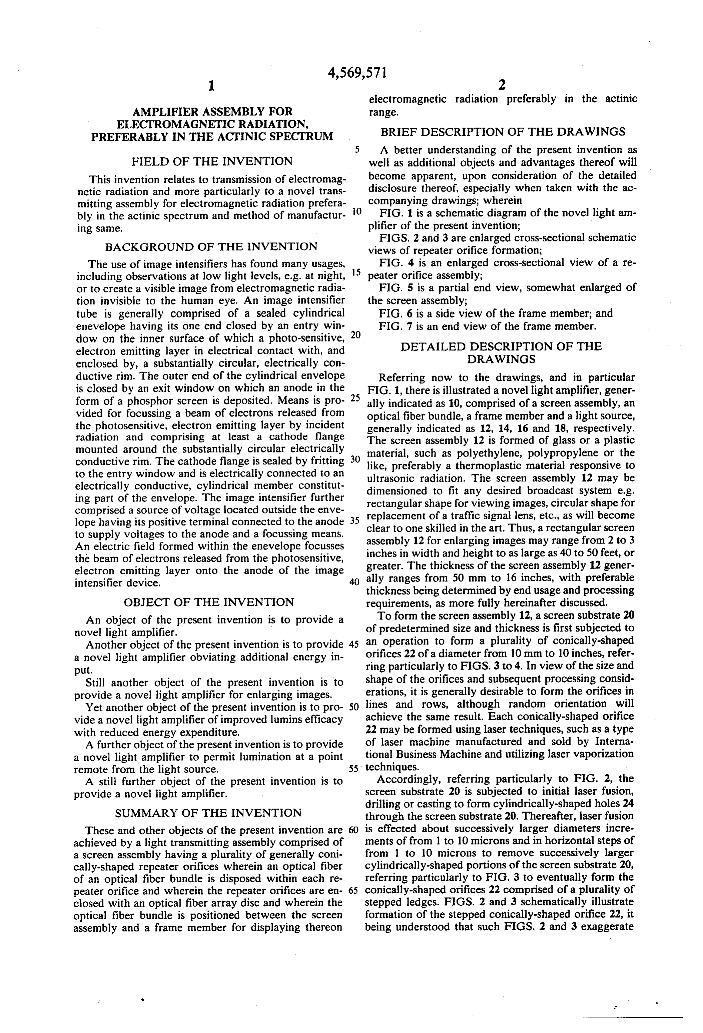
A better understanding of the present invention as
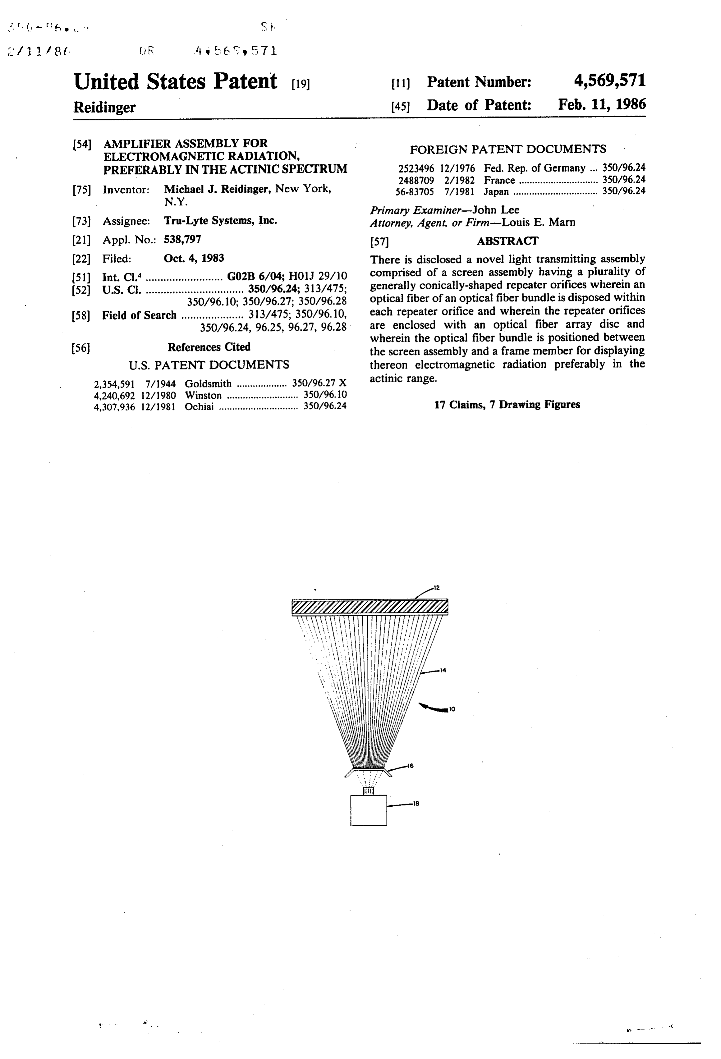
FIELD OF THE INVENTION well as additional objects and advantages thereof will This invention relates to transmission of electromag become apparent, upon consideration of the detailed netic radiation and more particularly to a novel trans disclosure thereof, especially when taken with the ac mitting assembly for electromagnetic radiation prefera O companying drawings; wherein bly in the actinic spectrum and method of manufactur FIG. 1 is a schematic diagram of the novel light am ing same. plifier of the present invention;
BACKGROUND OF THE INVENTION
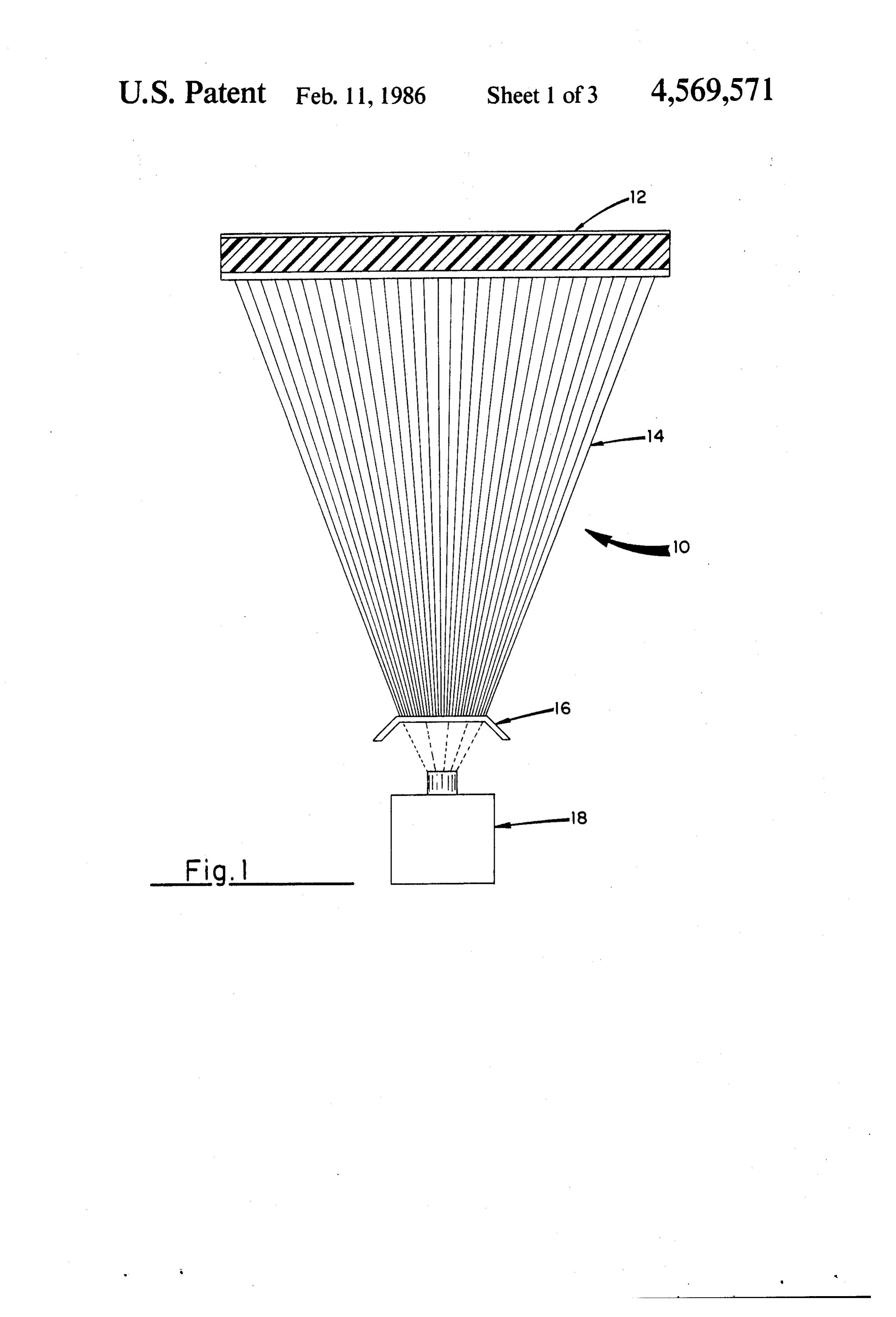
FIGS. 2 and 3 are enlarged cross-sectional schematic views of repeater orifice formation;
The use of image intensifiers has found many usages, FIG. 4 is an enlarged cross-sectional view of a re including observations at low light levels, e.g. at night, 15 peater orifice assembly;
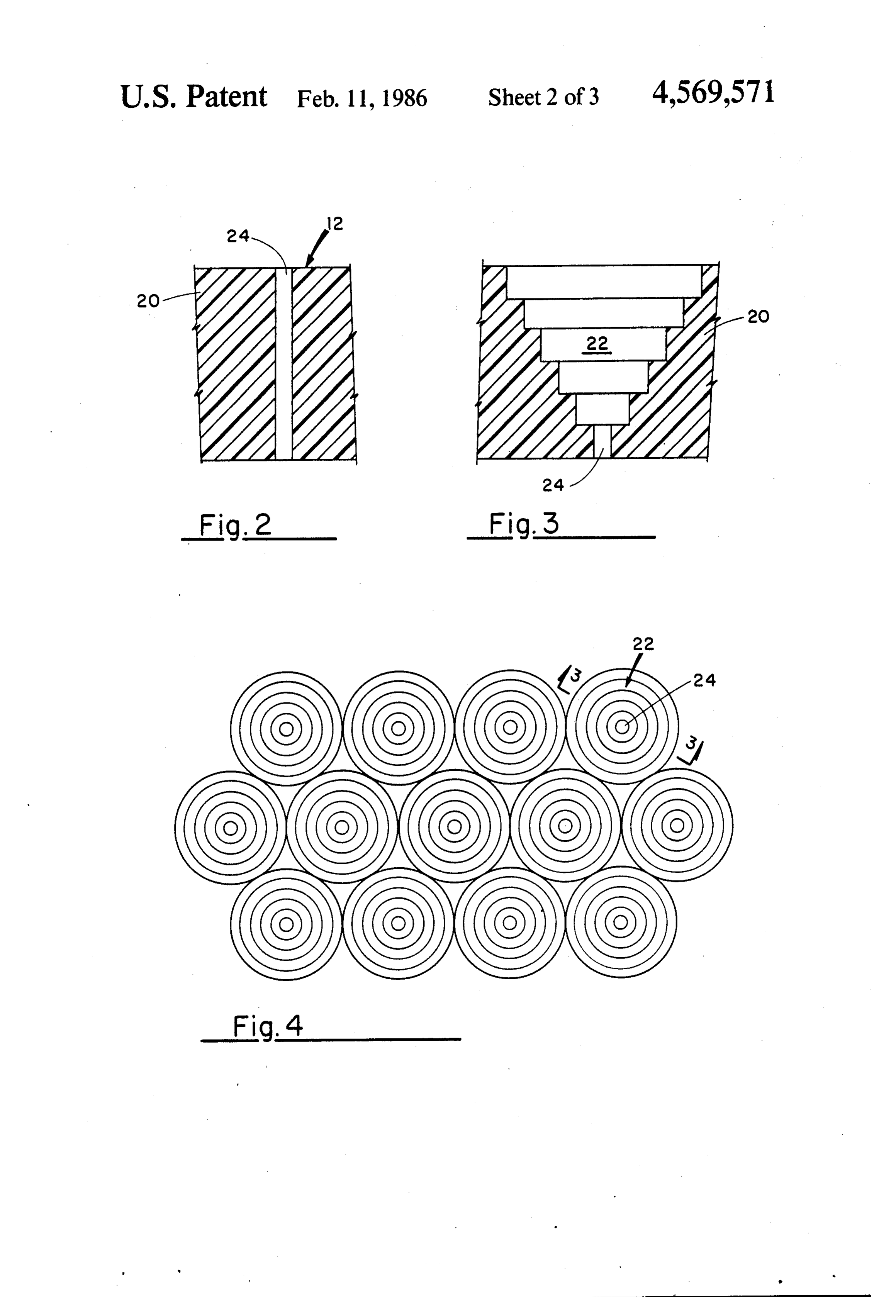
or to create a visible image from electromagnetic radia FIG. 5 is a partial end view, somewhat enlarged of tion invisible to the human eye. An image intensifier the screen assembly;
tube is generally comprised of a sealed cylindrical FIG. 6 is a side view of the frame member; and enevelope having its one end closed by an entry win 20 FIG. 7 is an end view of the frame member. dow on the inner surface of which a photo-sensitive, DETAILED DESCRIPTION OF THE electron emitting layer in electrical contact with, and DRAWINGS enclosed by, a substantially circular, electrically con ductive rim. The outer end of the cylindrical envelope Referring now to the drawings, and in particular is closed by an exit window on which an anode in the 25 FIG. 1, there is illustrated a novel light amplifier, gener form of a phosphor screen is deposited. Means is pro ally indicated as 10, comprised of a screen assembly, an vided for focussing a beam of electrons released from optical fiber bundle, a frame member and a light source, the photosensitive, electron emitting layer by incident generally indicated as 12, 14, 16 and 18, respectively. radiation and comprising at least a cathode flange The screen assembly 12 is formed of glass or a plastic mounted around the substantially circular electrically material, such as polyethylene, polypropylene or the conductive rim. The cathode flange is sealed by fritting 30 like, preferably a thermoplastic material responsive to to the entry window and is electrically connected to an ultrasonic radiation. The screen assembly 12 may be electrically conductive, cylindrical member constitut ing part of the envelope. The image intensifier further dimensioned to fit any desired broadcast system e.g. rectangular shape for viewing images, circular shape for comprised a source of voltage located outside the enve replacement of a traffic signal lens, etc., as will become lope having its positive terminal connected to the anode 35 clear to one skilled in the art. Thus, a rectangular screen to supply voltages to the anode and a focussing means. assembly
An electric field formed within the enevelope focusses inches in width and heightimages 12 for enlarging
may range from 2 to 3 large as 40 to 50 feet, or the beam of electrons released from the photosensitive, greater. The thickness of the screen assembly 12 gener electron emitting layer onto the anode of the image ally ranges from 50 mm to 16 inches, with preferable intensifier device. thickness being determined by end usage and processing OBJECT OF THE INVENTION requirements, as more fully hereinafter discussed. An object of the present invention is to provide a To form the screen assembly 12, a screen substrate 20 novel light amplifier. of predetermined size and thickness is first subjected to an operation to form a plurality of conically-shaped
Another object of the present invention is to provide 45 orifices a novel light amplifier obviating additional energy in 22 of a diameter from 10 mm to 10 inches, refer put. ring particularly to FIGS. 3 to 4. In view of the size and Still another object of the present invention is to shape of the orifices and subsequent processing consid provide a novel light amplifier for enlarging images. erations, it is generally desirable to form the orifices in Yet another object of the present invention is to pro 50 lines and rows, although random orientation will vide a novel light amplifier of improved lumins efficacy achieve the same result. Each conically-shaped orifice with reduced energy expenditure. 22 may be formed using laser techniques, such as a type A further object of the present invention is to provide of laser machine manufactured and sold by Interna a novel light amplifier to permit lumination at a point tional Business Machine and utilizing laser vaporization remote from the light source. 55 techniques.
A still further object of the present invention is to Accordingly, referring particularly to FIG. 2, the provide a novel light amplifier. screen substrate 20 is subjected to initial laser fusion, drilling or casting to form cylindrically-shaped holes 24
SUMMARY OF THE INVENTION through the screen substrate 20. Thereafter, laser fusion These and other objects of the present invention are 60 is effected about successively larger diameters incre achieved by a light transmitting assembly comprised of ments of from 1 to 10 microns and in horizontal steps of a screen assembly having a plurality of generally coni from 1 to 10 microns to remove successively larger cally-shaped repeater orifices wherein an optical fiber cylindrically-shaped portions of the screen substrate 20, of an optical fiber bundle is disposed within each re referring particularly to FIG. 3 to eventually form the peater orifice and wherein the repeater orifices are en 65 conically-shaped orifices 22 comprised of a plurality of closed with an optical fiber array disc and wherein the stepped ledges. FIGS. 2 and 3 schematically illustrate optical fiber bundle is positioned between the screen formation of the stepped conically-shaped orifice 22, it assembly and a frame member for displaying thereon being understood that such FIGS. 2 and 3 exaggerate
Page 6
stepping, and that in actuality successive laser radiation with ends thereof polished in a manner known to one is effected at as hereinabove described increasing diam skilled in the art.
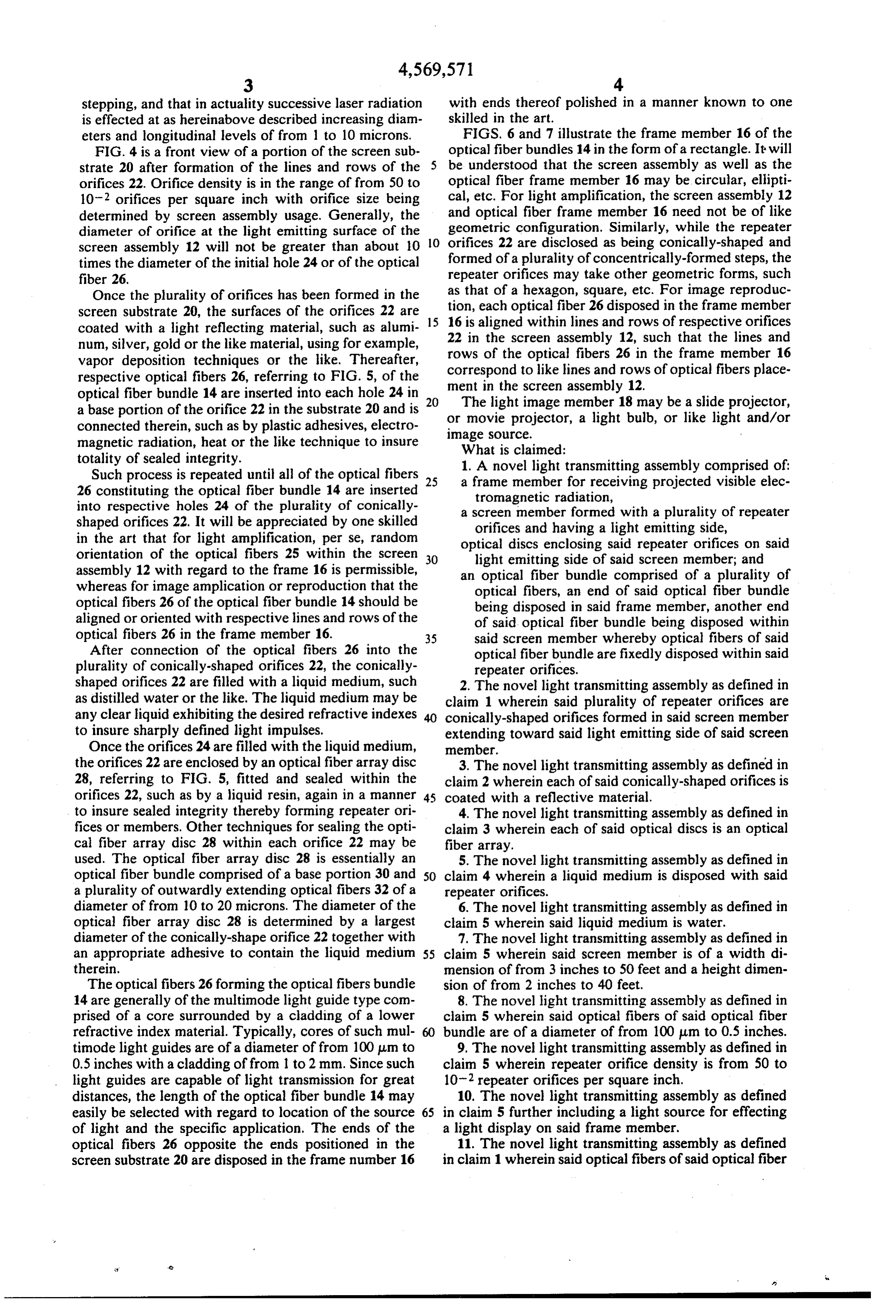
eters and longitudinal levels of from 1 to 10 microns. FIGS. 6 and 7 illustrate the frame member 16 of the FIG. 4 is a front view of a portion of the screen sub optical fiber bundles 14 in the form of a rectangle. It will strate 20 after formation of the lines and rows of the be understood that the screen assembly as well as the orifices 22. Orifice density is in the range of from 50 to optical fiber frame member 16 may be circular, ellipti 10-2 orifices per square inch with orifice size being cal, etc. For light amplification, the screen assembly 12 determined by screen assembly usage. Generally, the and optical fiber frame member 16 need not be of like diameter of orifice at the light emitting surface of the geometric configuration. Similarly, while the repeater screen assembly 12 will not be greater than about 10 O orifices 22 are disclosed as being conically-shaped and times the diameter of the initial hole 24 or of the optical formed of a plurality of concentrically-formed steps, the fiber 26, repeater orifices may take other geometric forms, such Once the plurality of orifices has been formed in the tion,thateach as of a hexagon, square, etc. For image reproduc optical fiber 26 disposed in the frame member screen substrate 20, the surfaces of the orifices 22 are coated with a light reflecting material, such as alumi 15 2216 is aligned within lines and rows of respective orifices num, silver, gold or the like material, using for example, in the screen assembly 12, such that the lines and vapor deposition techniques or the like. Thereafter, rows of the optical fibers 26 in the frame member 16 respective optical fibers 26, referring to FIG. 5, of the correspond ment in the to like lines and rows of optical fibers place screen assembly 12.
optical fiber bundle 14 are inserted into each hole 24 in a base portion of the orifice 22 in the substrate 20 and is or movie projector,member
The light image a light 18 may be a slide projector, bulb, or like light and/or connected therein, such as by plastic adhesives, electro image source.
magnetic radiation, heat or the like technique to insure What is claimed:
totality of sealed integrity.
Such process is repeated until all of the optical fibers 25 a1. frame
A novel light transmitting assembly comprised of:
member for receiving projected visible elec 26 constituting the optical fiber bundle 14 are inserted tromagnetic radiation, into respective holes 24 of the plurality of conically a screen member formed with a plurality of repeater shaped orifices 22. It will be appreciated by one skilled orifices and having a light emitting side, in the art that for light amplification, per se, random optical discs enclosing said repeater orifices on said orientation of the optical fibers 25 within the screen 30 light emitting side of said screen member; and assembly 12 with regard to the frame 16 is permissible, an optical fiber bundle comprised of a plurality of whereas for image amplication or reproduction that the optical fibers, an end of said optical fiber bundle optical fibers 26 of the optical fiber bundle 14 should be being disposed in said frame member, another end aligned or oriented with respective lines and rows of the of said optical fiber bundle being disposed within optical fibers 26 in the frame member 16. 35 said screen member whereby optical fibers of said After connection of the optical fibers 26 into the optical fiber bundle are fixedly disposed within said plurality of conically-shaped orifices 22, the conically repeater orifices.
shaped orifices 22 are filled with a liquid medium, such 2. The novel light transmitting assembly as defined in as distilled water or the like. The liquid medium may be claim 1 wherein said plurality of repeater orifices are any clear liquid exhibiting the desired refractive indexes conically-shaped orifices formed in said screen member to insure sharply defined light impulses. extending toward said light emitting side of said screen Once the orifices 24 are filled with the liquid medium, member.
the orifices 22 are enclosed by an optical fiber array disc 3. The novel light transmitting assembly as defined in 28, referring to FIG. 5, fitted and sealed within the claim 2 wherein each of said conically-shaped orifices is orifices 22, such as by a liquid resin, again in a manner 45 coated with a reflective material. to insure sealed integrity thereby forming repeater ori 4. The novel light transmitting assembly as defined in fices or members. Other techniques for sealing the opti claim 3 wherein each of said optical discs is an optical cal fiber array disc 28 within each orifice 22 may be fiber array.
used. The optical fiber array disc 28 is essentially an 5. The novel light transmitting assembly as defined in optical fiber bundle comprised of a base portion 30 and 50 claim 4 wherein a liquid medium is disposed with said a plurality of outwardly extending optical fibers 32 of a repeater orifices.
diameter of from 10 to 20 microns. The diameter of the 6. The novel light transmitting assembly as defined in optical fiber array disc 28 is determined by a largest claim 5 wherein said liquid medium is water. diameter of the conically-shape orifice 22 together with 7. The novel light transmitting assembly as defined in an appropriate adhesive to contain the liquid medium 55 claim 5 wherein said screen member is of a width di therein. mension of from 3 inches to 50 feet and a height dimen The optical fibers 26 forming the optical fibers bundle sion of from 2 inches to 40 feet.
14 are generally of the multimode light guide type com 8. The novel light transmitting assembly as defined in prised of a core surrounded by a cladding of a lower claim 5 wherein said optical fibers of said optical fiber refractive index material. Typically, cores of such mul bundle are of a diameter of from 100 um to 0.5 inches. timode light guides are of a diameter of from 100 m to 9. The novel light transmitting assembly as defined in 0.5 inches with a cladding of from 1 to 2 mm. Since such claim 5 wherein repeater orifice density is from 50 to light guides are capable of light transmission for great 10-2 repeater orifices per square inch. distances, the length of the optical fiber bundle 14 may 10. The novel light transmitting assembly as defined easily be selected with regard to location of the source 65 in claim 5 further including a light source for effecting of light and the specific application. The ends of the a light display on said frame member.
optical fibers 26 opposite the ends positioned in the 11. The novel light transmitting assembly as defined screen substrate 20 are disposed in the frame number 16 in claim 1 wherein said optical fibers of said optical fiber
Page 7
bundle are aligned in respective lines and rows in said 13. The method as defined in claim 12 wherein a frame member and said screen member. liquid medium is disposed within each of said conically 12. A method of forming a screen assembly, which shaped orifices before step (d). 14. The method as defined in claim 13 wherein said comprises: 5 screen substrate is of a thickness of from 50 mm to 16 (a) forming a plurality of conically-shaped orifices in inches.
a screen substrate; 15. The method as defined in claim 13 wherein said (b) coating said conically-shaped orifices with a light screen substrate is of a width dimension of from 3 inches reflective material; to 50 feet and a height dimension of from 2 inches to 40 O feet.
(c) affixing an optical fiber of an optical fiber bundle 16. The method as defined in claim 13 wherein orifice into a base portion of each of said conically-shaped density is of from 50 to 10-2 orifices per square inch. orifices; and 17. The method defined in claim 13 wherein said (d) affixing a fiber array disc into a top portion of liquid is water. k each of said conically-shaped orifices. 5
Provenance
- Collection
- Cited prior art
- Original PDF
- patentimages.storage.googleapis.com →
- Filed
- 1983-10-04
- Pages
- 7
- Method
- pdftotext (the PDF's own text layer) + pdftoppm 300dpi page scans
- Source
- Google Patents bibliographic record
- Granted
- 1986-02-11
- Inventors
- Michael J. Reidinger; TRU LYTE SYSTEMS Inc
- Transcribed from
- patentimages.storage.googleapis.com →