patent · US4088121
Solar energy concentrator
9 May 1978
Page 1 — bibliographic record
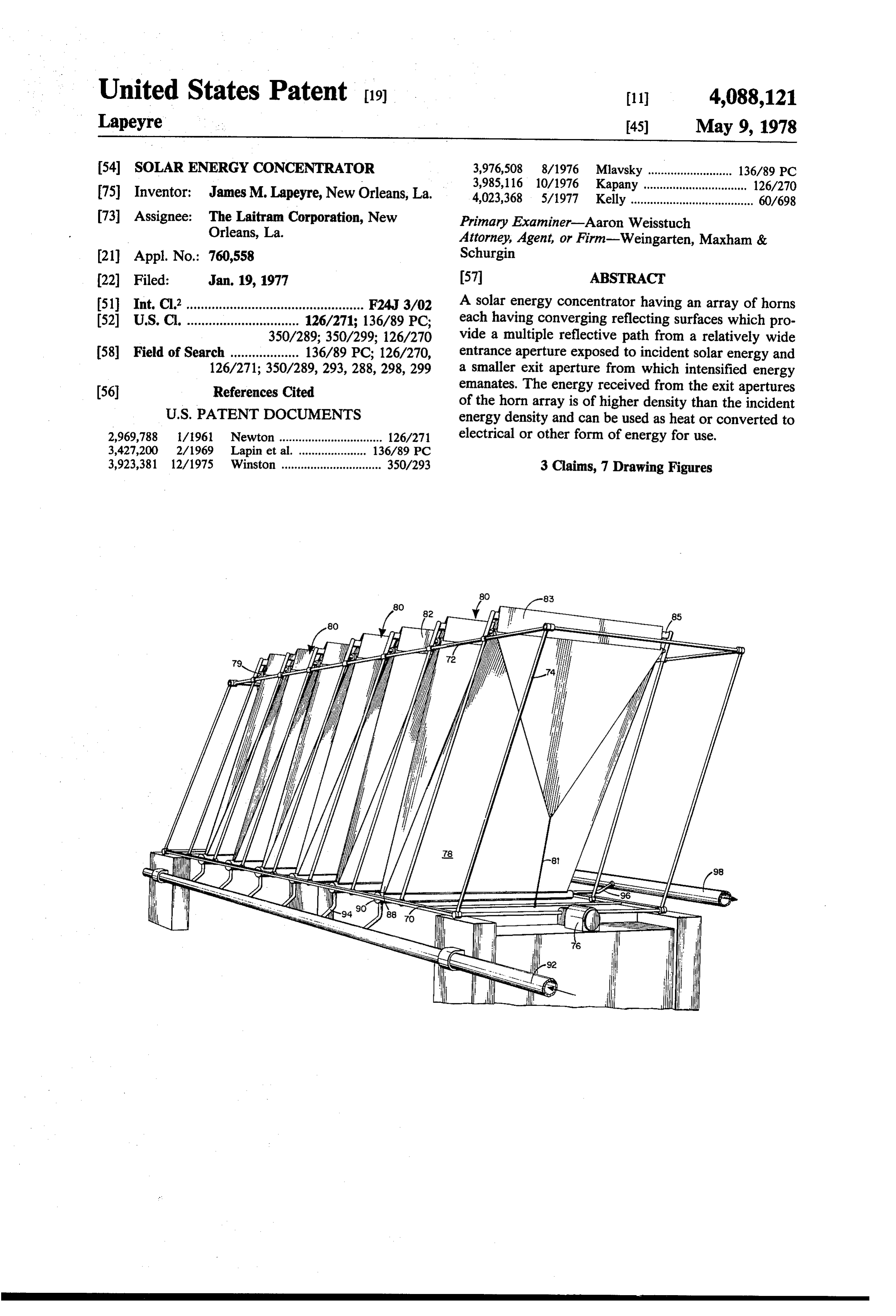
United States Patent (19) 11 4,088,121 Lapeyre 45) May 9, 1978 54 SOLAR ENERGY CONCENTRATOR 3,976,508 8/1976 Mlavsky .......................... 136/89 PC (75) Inventor: James M. Lapeyre, New Orleans, La. 3,985,116 10/1976 Kapany ................................ 126/270 4,023,368 5/1977 Kelly...................................... 60/698 (73) Assignee: The Laitram Corporation, New Primary Examiner-Aaron Weisstuch Orleans, La. Attorney, Agent, or Firm-Weingarten, Maxham & (21) Appl. No.: 760,558 Schurgin 22) Filed: Jan. 19, 1977 57 ABSTRACT 51 Int. Cl’................................................. F24J 3/02 A solar energy concentrator having an array of horns (52) U.S. C. ............................... 126/271; 136/89 PC; each having converging reflecting surfaces which pro 350/289; 350/299; 126/270 vide a multiple reflective path from a relatively wide (58) Field of Search ................... 136/89 PC; 126/270, entrance aperture exposed to incident solar energy and 126/271; 350/289, 293,288, 298, 299 a smaller exit aperture from which intensified energy (56) References Cited emanates. The energy received from the exit apertures of the horn array is of higher density than the incident
2,969,788 iM1961 Newton ................................ 126/271 electrical or other form of energy for use. 3,427,200 2/1969 Lapin et al. .. ... 136/89 PC 3,923,381 12/1975 Winston ............................... 350/293 3 Claims, 7 Drawing Figures
Page 2
Drawing sheet — no readable text.
Page 3
Drawing sheet — no readable text.
Page 4
Drawing sheet — no readable text.
Page 5
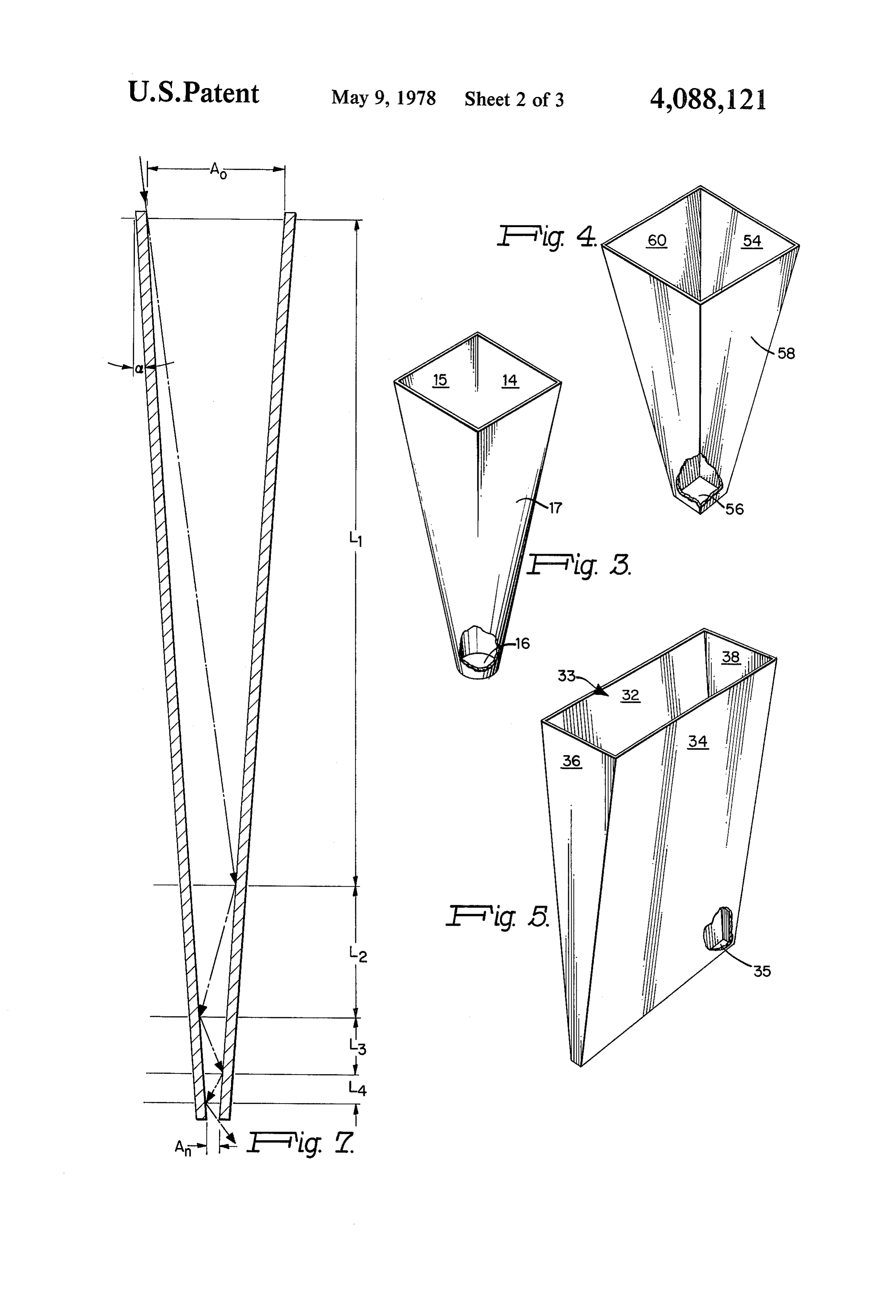
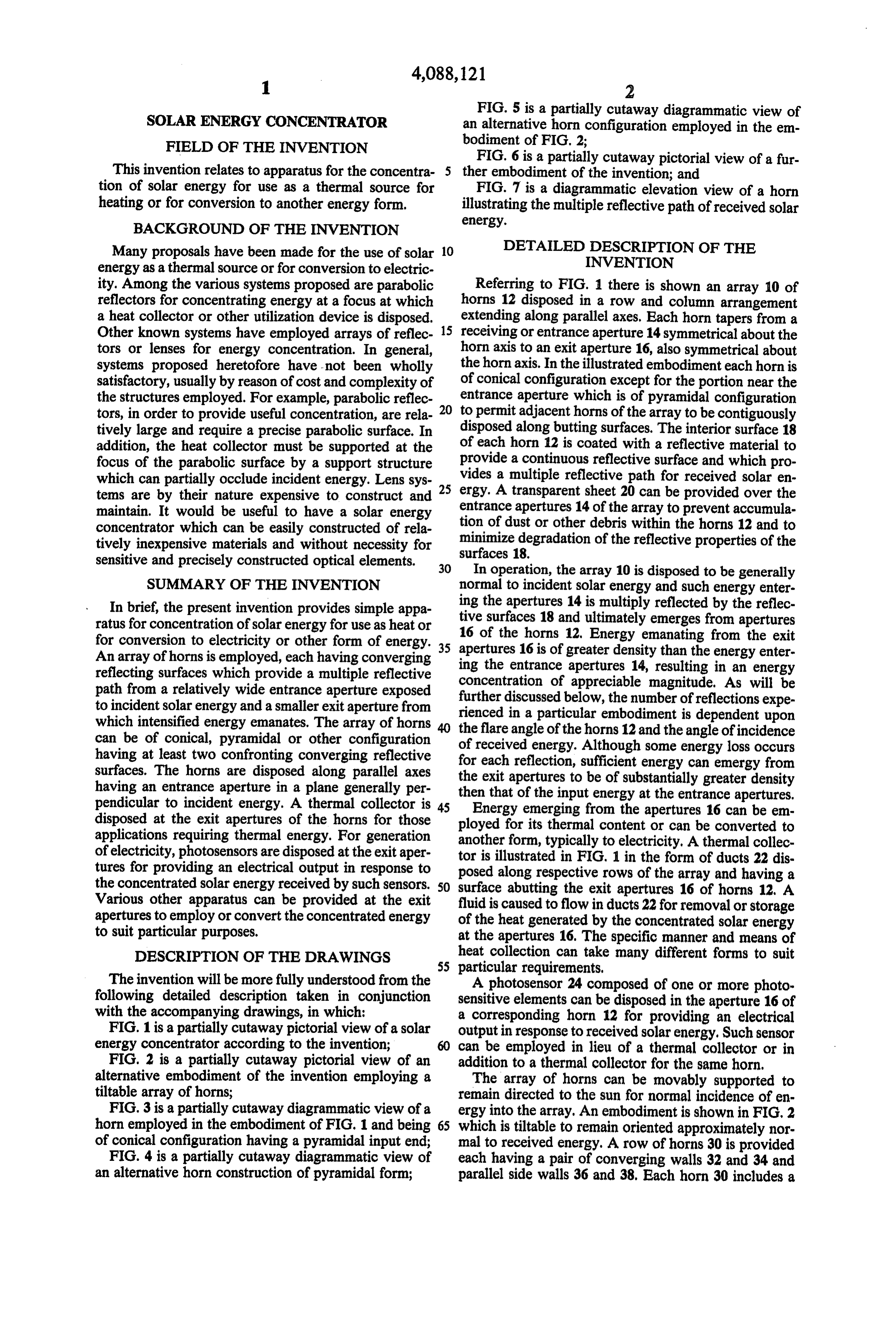
FIG. 5 is a partially cutaway diagrammatic view of
SOLAR ENERGY CONCENTRATOR an alternative horn configuration employed in the em FIELD OF THE INVENTION bodiment of FIG. 2;
FIG. 6 is a partially cutaway pictorial view of a fur
This invention relates to apparatus for the concentra ther embodiment of the invention; and tion of solar energy for use as a thermal source for FIG. 7 is a diagrammatic elevation view of a horn heating or for conversion to another energy form. illustrating the multiple reflective path of received solar energy.
BACKGROUND OF THE INVENTION
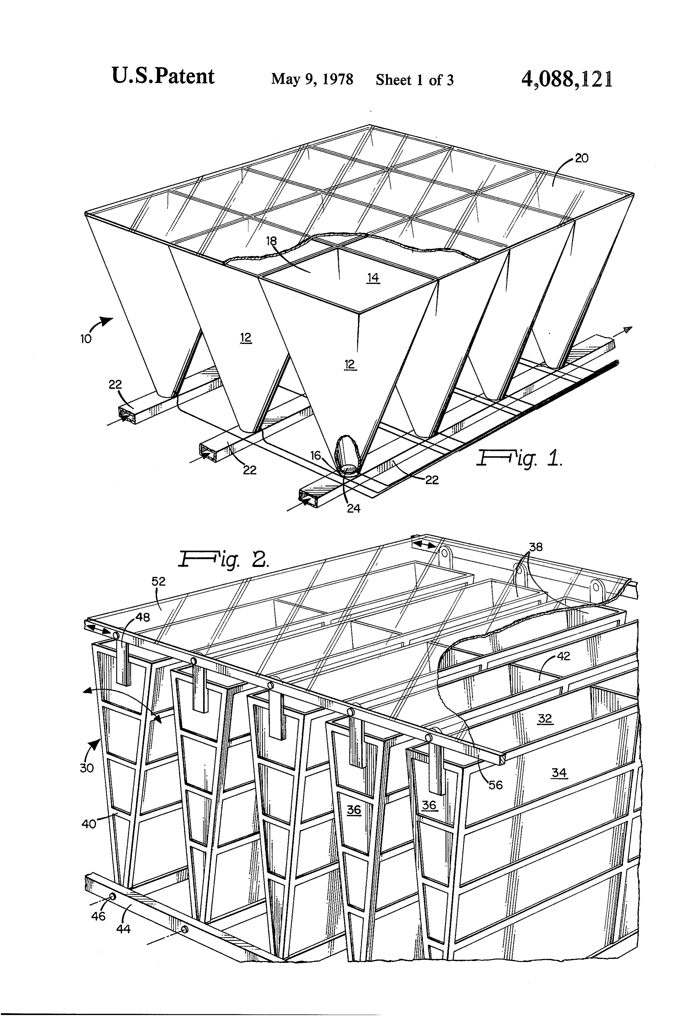
Many proposals have been made for the use of solar 10 DETAILED DESCRIPTION OF THE energy as a thermal source or for conversion to electric INVENTION ity. Among the various systems proposed are parabolic Referring to FIG. 1 there is shown an array 10 of reflectors for concentrating energy at a focus at which horns 12 disposed in a row and column arrangement a heat collector or other utilization device is disposed. extending along parallel axes. Each horn tapers from a Other known systems have employed arrays of reflec 15 receiving or entrance aperture 14 symmetrical about the tors or lenses for energy concentration. In general, horn axis to an exit aperture 16, also symmetrical about systems proposed heretofore have not been wholly the horn axis. In the illustrated embodiment each horn is satisfactory, usually by reason of cost and complexity of of conical configuration except for the portion near the the structures employed. For example, parabolic reflec entrance aperture which is of pyramidal configuration tors, in order to provide useful concentration, are rela 20 to permit adjacent horns of the array to be contiguously tively large and require a precise parabolic surface. In disposed along butting surfaces. The interior surface 18 addition, the heat collector must be supported at the of each horn 12 is coated with a reflective material to focus of the parabolic surface by a support structure provide a continuous reflective surface and which pro which can partially occlude incident energy. Lens sys 25 vides a multiple reflective path for received solar en tems are by their nature expensive to construct and ergy. A transparent sheet 20 can be provided over the maintain. It would be useful to have a solar energy entrance apertures 14 of the array to prevent accumula tion of dust or other debris within the horns 12 and to concentrator which can be easily constructed of rela minimize degradation of the reflective properties of the tively inexpensive materials and without necessity for surfaces 18.
sensitive and precisely constructed optical elements. 30 In operation, the array 10 is disposed to be generally SUMMARY OF THE INVENTION normal to incident solar energy and such energy enter In brief, the present invention provides simple appa tive ing the apertures 14 is multiply reflected by the reflec ratus for concentration of solar energy for use as heat or 16 ofsurfaces 18 and ultimately emerges from apertures for conversion to electricity or other form of energy. 35 apertures 16 is of 12.
the horns Energy emanating from the exit greater density than the energy enter
An array of horns is employed, each having converging ing the entrance apertures reflecting surfaces which provide a multiple reflective concentration of appreciable14, magnitude.resulting in an energy As will be path from a relatively wide entrance aperture exposed further discussed below, the number of reflections to incident solar energy and a smaller exit aperture from rienced in a particular embodiment is dependent expe upon which intensified energy emanates. The array of horns the flare angle of the horns 12 and the angle of incidence can be of conical, pyramidal or other configuration of received energy. Although some energy loss occurs having at least two confronting converging reflective for each reflection, sufficient energy can emergy from surfaces. The horns are disposed along parallel axes the having an entrance aperture in a plane generally per thenexit apertures to be of substantially greater density that of the input energy at the entrance apertures.
pendicular to incident energy. A thermal collector is 45 Energy emerging from the apertures 16 can be em disposed at the exit apertures of the horns for those ployed applications requiring thermal energy. For generation anotherfor its thermal content or can be converted to of electricity, photosensors are disposed at the exit aper tor is illustratedtypically form, to electricity, Athermal collec in FIG. 1 in the form of ducts 22 dis tures for providing an electrical output in response to posed along respective rows of the array and having a the concentrated solar energy received by such sensors. SO surface abutting the exit apertures 16 of horns 12, A Various other apparatus can be provided at the exit fluid is caused to flow inducts 22 for removal or storage apertures to employ or convert the concentrated energy of the heat generated by the concentrated solar energy to suit particular purposes. at the apertures 16. The specific manner and means of DESCRIPTION OF THE DRAWINGS heat collection can take many different forms to suit 55 particular requirements,
The invention will be more fully understood from the A photosensor 24 composed of one or more photo following detailed description taken in conjunction sensitive elements can be disposed in the aperture 16 of with the accompanying drawings, in which: a corresponding horn 12 for providing an electrical FIG. 1 is a partially cutaway pictorial view of a solar output in response to received solar energy. Such sensor energy concentrator according to the invention; 60
FIG. 2 is a partially cutaway pictorial view of an can be employed in lieu of a thermal collector or in addition to a thermal collector for the same horn.
alternative embodiment of the invention employing a The array of horns can be movably supported to tiltable array of horns; remain directed to the sun for normal incidence of en FIG. 3 is a partially cutaway diagrammatic view of a ergy into the array. An embodiment is shown in FIG.2 horn employed in the embodiment of FIG. 1 and being 65 which is tiltable to remain oriented approximately nor of conical configuration having a pyramidal input end; mal to received energy. A row of horns 30 is provided FIG. 4 is a partially cutaway diagrammatic view of each having a pair of converging walls 32 and 34 and an alternative horn construction of pyramidal form; parallel side walls 36 and 38. Each horn 30 includes a
Page 6
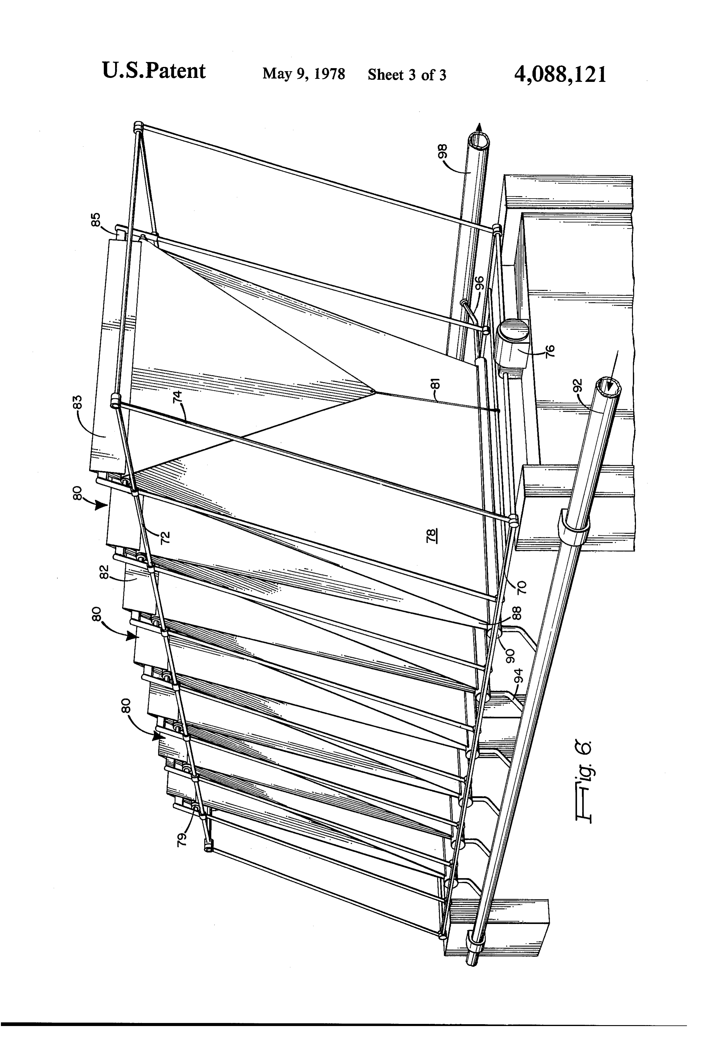
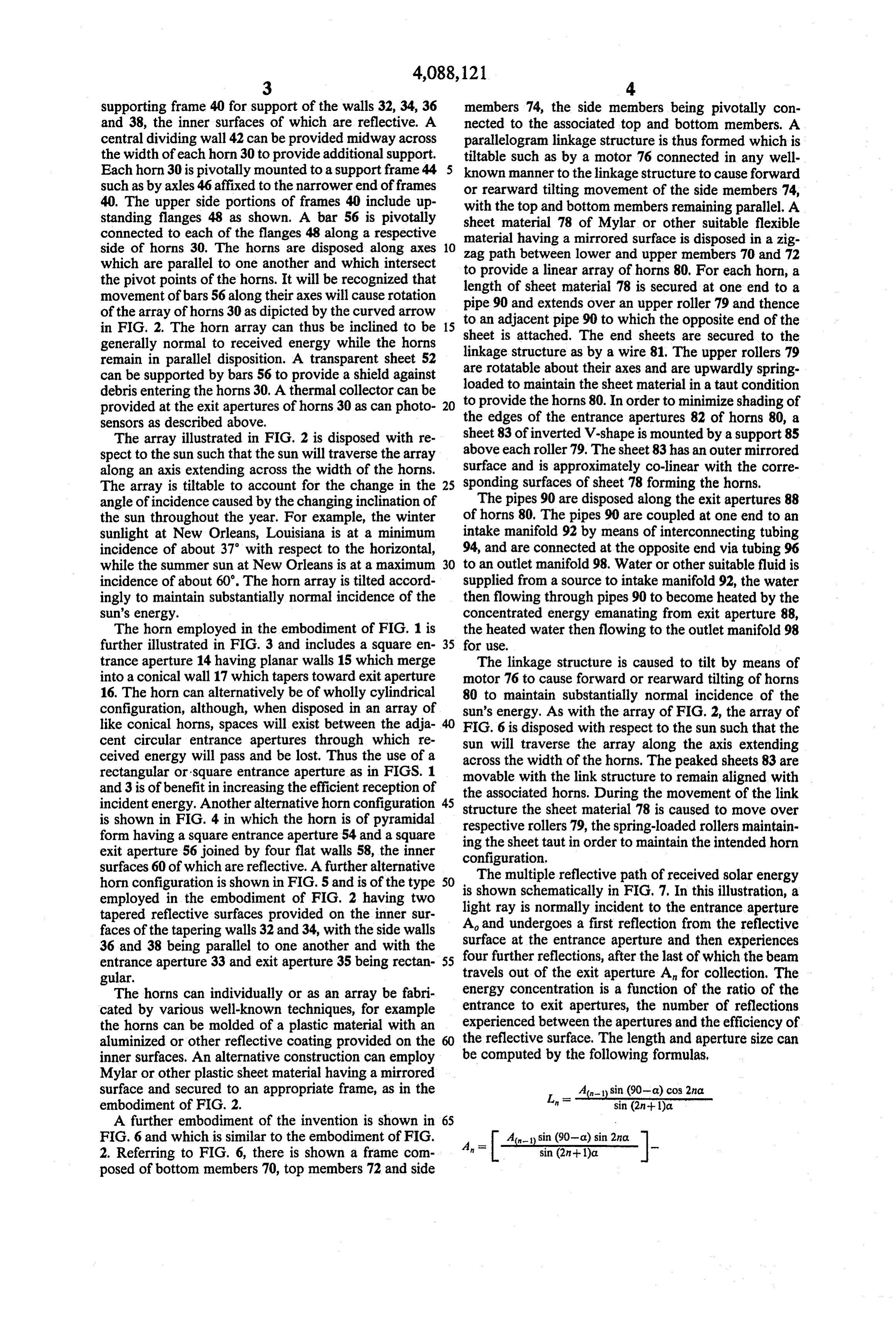
supporting frame 40 for support of the walls 32, 34, 36 members 74, the side members being pivotally con and 38, the inner surfaces of which are reflective. A nected to the associated top and bottom members. A central dividing wall 42 can be provided midway across parallelogram linkage structure is thus formed which is the width of each horn 30 to provide additional support. tiltable such as by a motor 76 connected in any well Each horn 30 is pivotally mounted to a support frame 44 5 known manner to the linkage structure to cause forward such as by axles 46 affixed to the narrower end of frames or rearward tilting movement of the side members 74, 40. The upper side portions of frames 40 include up with the top and bottom members remaining parallel. A standing flanges 48 as shown. A bar 56 is pivotally sheet material 78 of Mylar or other suitable flexible connected to each of the flanges 48 along a respective material side of horns 30. The horns are disposed along axes 10 zag path having a mirrored surface is disposed in a zig which are parallel to one another and which intersect to provide a linearlower between array and upper members 70 and 72 of horns 80. For each horn, a the pivot points of the horns. It will be recognized that length of sheet material 78 movement of bars 56 along their axes will cause rotation pipe 90 and extends over an isupper secured at one end to a of the array of horns 30 as dipicted by the curved arrow to an adjacent pipe 90 to which theroller 79 and thence opposite end of the in FIG. 2. The horn array can thus be inclined to be 15 sheet generally normal to received energy while the horns linkageis structure attached. The end sheets are secured to the as by a wire 81. The upper rollers 79 remain in parallel disposition. A transparent sheet 52 can be supported by bars 56 to provide a shield against are rotatable about their axes and are upwardly spring loaded to maintain the sheet material in a taut condition debris entering the horns 30. A thermal collector can be to provided at the exit apertures of horns 30 as can photo 20 theprovide the horns 80. In order to minimize shading of edges of the entrance apertures 82 of horns 80, a sensors as described above.
The array illustrated in FIG. 2 is disposed with re sheet 83 of inverted V-shape is mounted by a support 85 spect to the sun such that the sun will traverse the array above surface each roller 79. The sheet 83 has an outer mirrored and is approximately co-linear with the corre along an axis extending across the width of the horns.
The array is tiltable to account for the change in the 25 sponding surfaces of sheet 78 forming the horns, angle of incidence caused by the changing inclination of The pipes 90 are disposed along the exit apertures 88 the sun throughout the year. For example, the winter of horns 80, The pipes 90 are coupled at one end to an sunlight at New Orleans, Louisiana is at a minimum intake manifold 92 by means of interconnecting tubing incidence of about 37 with respect to the horizontal, 94, and are connected at the opposite end via tubing 96 while the summer sun at New Orleans is at a maximum 30 to an outlet manifold 98. Water or other suitable fluid is incidence of about 60'. The horn array is tilted accord supplied from a source to intake manifold 92, the water ingly to maintain substantially normal incidence of the then flowing through pipes 90 to become heated by the Sun's energy. concentrated energy emanating from exit aperture 88, The horn employed in the embodiment of FIG. 1 is the heated water then flowing to the outlet manifold 98 further illustrated in FIG. 3 and includes a square en 35 for use.
trance aperture 14 having planar walls 15 which merge The linkage structure is caused to tilt by means of into a conical wall 17 which tapers toward exit aperture motor 76 to cause forward or rearward tilting of horns 16. The horn can alternatively be of wholly cylindrical 80 to maintain substantially normal incidence of the configuration, although, when disposed in an array of sun's energy. As with the array of FIG. 2, the array of like conical horns, spaces will exist between the adja 40 FIG. 6 is disposed with respect to the sun such that the cent circular entrance apertures through which re sun will traverse the array along the axis extending ceived energy will pass and be lost. Thus the use of a across the width of the horns. The peaked sheets 83 are rectangular or square entrance aperture as in FIGS. 1 and 3 is of benefit in increasing the efficient reception of movable the with the link structure to remain aligned with associated horns. During the movement of the link incident energy. Another alternative horn configuration 45 structure the sheet material 78 is caused to move over is shown in FIG. 4 in which the horn is of pyramidal respective rollers 79, the spring-loaded rollers maintain form having a square entrance aperture 54 and a square ing the sheet taut in order to maintain the intended horn exit aperture 56 joined by four flat walls 58, the inner configuration.
surfaces 60 of which are reflective. A further alternative
The multiple reflective path of received solar energy horn configuration is shown in FIG. 5 and is of the type SO is shown employed in the embodiment of FIG. 2 having two light ray isschematically normally in FIG, 7. In this illustration, a incident to the entrance aperture tapered reflective surfaces provided on the inner sur A and undergoes a first reflection faces of the tapering walls 32 and 34, with the side walls surface at the entrance aperture andfrom then the reflective experiences 36 and 38 being parallel to one another and with the four further reflections, after the last of which the beam entrance aperture 33 and exit aperture 35 being rectan 55 gular. travels out of the exit aperture A for collection. The The horns can individually or as an array be fabri energy concentration is a function of the ratio of the cated by various well-known techniques, for example entrance to exit apertures, the number of reflections the horns can be molded of a plastic material with an experienced between the apertures and the efficiency of aluminized or other reflective coating provided on the 60 the reflective surface. The length and aperture size can inner surfaces. An alternative construction can employ be computed by the following formulas, Mylar or other plastic sheet material having a mirrored surface and secured to an appropriate frame, as in the In
A-sin (90-a) cos 2nd embodiment of FIG. 2. sin (2n+1)a A further embodiment of the invention is shown in 65
FIG. 6 and which is similar to the embodiment of FIG. sin (90-d) sin 2na. 2. Referring to FIG. 6, there is shown a frame com posed of bottom members 70, top members 72 and side
Page 7
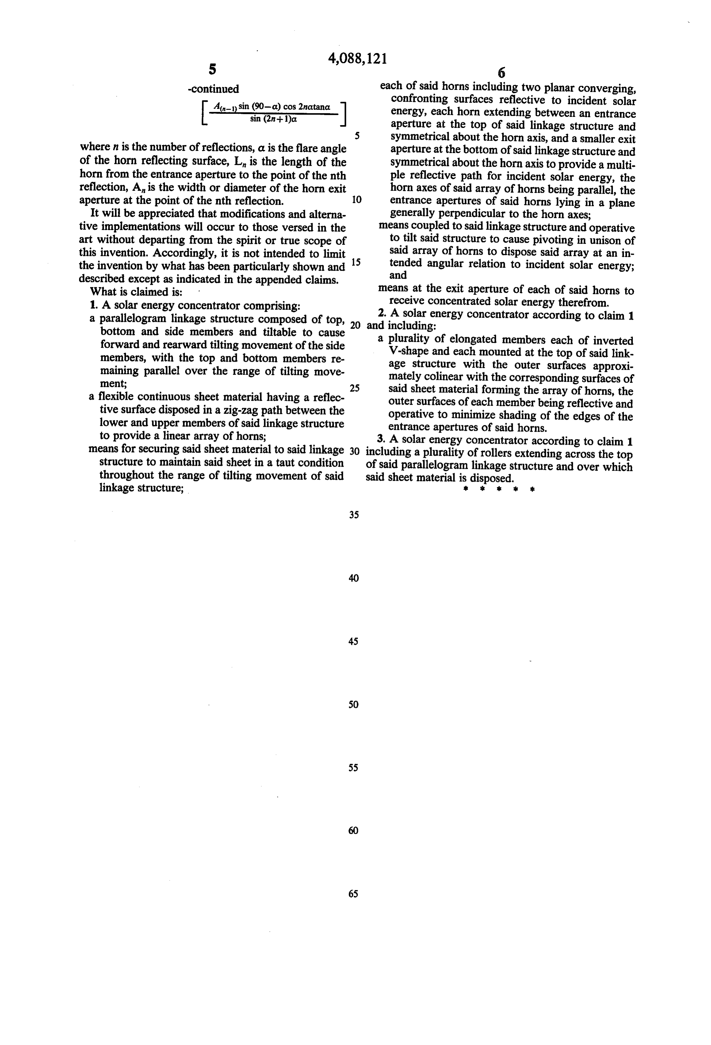
-continued each of said horns including two planar converging, 4-D sin (90-a) cos 2natana.
confronting surfaces reflective to incident solar sin (2n+1)a energy, each horn extending between an entrance aperture at the top of said linkage structure and symmetrical about the horn axis, and a smaller exit where n is the number of reflections, a is the flare angle aperture at the bottom of said linkage structure and of the horn reflecting surface, L is the length of the symmetrical about the horn axis to provide a multi horn from the entrance aperture to the point of the nth ple reflective path for incident solar energy, the reflection, A is the width or diameter of the horn exit horn axes of said array of horns being parallel, the aperture at the point of the nth reflection. 10 entrance apertures of said horns lying in a plane It will be appreciated that modifications and alterna generally perpendicular to the horn axes; tive implementations will occur to those versed in the means coupled to said linkage structure and operative art without departing from the spirit or true scope of to tilt said structure to cause pivoting in unison of this invention. Accordingly, it is not intended to limit 15 said array of horns to dispose said array at an in the invention by what has been particularly shown and tended angular relation to incident solar energy; described except as indicated in the appended claims. and
What is claimed is: means at the exit aperture of each of said horns to 1. A solar energy concentrator comprising: receive concentrated solar energy therefrom. a parallelogram linkage structure composed of top, 20 and2. including:
A solar energy concentrator according to claim 1 bottom and side members and tiltable to cause forward and rearward tilting movement of the side a plurality of elongated members each of inverted members, with the top and bottom members re V-shape and each mounted at the top of said link maining parallel over the range of tilting move age structure with the outer surfaces approxi ment; mately colinear with the corresponding surfaces of 25 said sheet material forming the array of horns, the a flexible continuous sheet material having a reflec outer surfaces of each member being reflective and tive surface disposed in a zig-zag path between the operative to minimize shading of the edges of the lower and upper members of said linkage structure entrance apertures of said horns. to provide a linear array of horns; 3. A solar energy concentrator according to claim 1 means for securing said sheet material to said linkage 30 including a plurality of rollers extending across the top structure to maintain said sheet in a taut condition of said parallelogram linkage structure and over which throughout the range of tilting movement of said said sheet material is disposed.
linkage structure; k . . . .
Provenance
- Collection
- Cited prior art
- Original PDF
- patentimages.storage.googleapis.com →
- Filed
- 1977-01-19
- Pages
- 7
- Method
- pdftotext (the PDF's own text layer) + pdftoppm 300dpi page scans
- Source
- Google Patents bibliographic record
- Granted
- 1978-05-09
- Inventors
- James M. Lapeyre; Laitram LLC
- Transcribed from
- patentimages.storage.googleapis.com →