patent · US4240692
Energy transmission
23 December 1980
Page 1 — bibliographic record
- - v st V
United States Patent (19) (11) 4,240,692 Winston
(54) ENERGY TRANSMISSION
FOREIGN PATENT DOCUMENTS
75 Inventor: Roland Winston, Chicago, Ill.
(73) Assignee: The University of Chicago, Chicago, 1472267 12/1969 Fed. Rep. of Germany ........ 350/96 R II. OTHER PUBLICATIONS (21) Appl. No.: 641,557 Light Guide Arrangement with Strong Concentrating 22 Filed: Dec. 17, 1975 Effect by M. Ploke in Optik, No. 1, pp. 31-43, (1967). Primary Examiner-Stewart J. Levy
Related U.S. Application Data Attorney, Agent, or Firm-Merriam, Marshall & Bicknell 63 Continuation-in-part of Ser. No. 628,383, Nov. 3, 1975, (57) ABSTRACT abandoned.
Disclosed are radiant energy transmitting devices oper (51 Int. Cl. ............................ G02B 5/14; F24J 3/02 ative selectively in concentrative and emissive modes, 52 U.S. Cl. ................................. 350/96.10; 126/438: having transmitting elements including radiant energy 126/441; 350/293; 350/294 transmitting and guiding surfaces at the interface of 58) Field of Search ..................... 350/96 R, 293, 294, media of differing indices of refraction for radiant en 350/258, 263-265; 126/270, 271, 438, 441; ergy. Surfaces generally are of a concavely sloping 136/89 PC, 206; 237/1 A configuration consistent with reflecting, for example, 56 References Cited extremal energy rays entering the element from within a defined field of acceptance at an energy inlet onto an
3,437,804 4/1969 Schaefer et al. ................... 350/96 R energy source through an energy outlet within a de 3,467,840 9/1969 Weiner ............ ... 350/96 R fined field of emission. The energy source or trap is 3,883,731 5/1975 Morton et al ... 350/96 R preferably an energy transducer such as a photoelectric 3,899,672 8/1975 Levi-Setti ............................ 350/294 device.
3,923,381 12/1975 Winston ...... ... 350/294 3,995,935 12/1976 McCartney .......................... 350/293 24 Claims, 13 Drawing Figures
Page 2
Drawing sheet — no readable text.
Page 3
Drawing sheet — no readable text.
Page 4
Drawing sheet — no readable text.
Page 5
Drawing sheet — no readable text.
Page 6
ENERGY TRANSMISSION like and conical configurations have met with substan tial success, especially in applications involving collec
CROSS-REFERENCE TO RELATED tion and concentration of solar energy. Thus, for exam APPLICATION ple, my U.S. Pat. No. 3,923,381 discloses, inter alia, non-imaging radiant energy collecting and concentrat
This is a continuation-in-part of my co-pending appli ing devices generally including opposed reflective sur cation Ser. No. 628,383 now abandoned, filed Nov. 3, faces sloped to reflect the maximum angle energy rays 1975. within the device's field of acceptance on an energy BACKGROUND OF THE INVENTION 10 trap-allowing concentration by substantial factors, avoidance of transient energy source tracking and gen
The present invention relates generally to transmis eral minimization of absorptive losses due to multiple sion of radiant energy and more particularly to devices reflections. In a similar manner, U.S. Pat. No. 3,899,672 which may be constructed to collect radiant energy of Levi-Setti discloses, inter alia, non-imaging conical from within a field of selected angular characteristics or ly-shaped energy collectors and concentrators having alternatively to emit radiant energy throughout a field 15 similarly advantageous energy transmission characteris of selected angular characteristics or both. As such, the tics. Complimentary disclosures relative to this subject invention relates to radiant energy concentrative and matter are contained in my publications, "Principles Of emissive functions and combinations thereof useful for such purposes as energy display, energy transformation Solar Concentrators Of A Novel Design," Solar Energy, and coupling other energy transmission devices. De 20 Vol. 16, pp. 89-95 (1974) and Solar Energy Concentra vices according to the present invention include radiant tions, Progress Report NSF/RANN AER 75-01065 energy reflecting and guiding walls developed at the (February, 1975), the latter of which specifically relates interface of media of differing indices of refraction for to principles for maximally concentrating radiant en radiant energy and optimally operative to substantially ergy onto a tube receiver through use of cylindrical provide total internal reflection of such radiant energy. 25 trough-like reflecting wall light channels of specific The prior art has proposed and includes numerous shape which concentrate radiant energy by the maxi structures and devices for electromagnetic or radiant mum amount allowed by phase space conservation. energy detection, collection, concentration, transmis To the extent that my said U.S. Pat. Nos. 3,923,381, sion, transformation, propagation and emission of 3,899,672, my recent publications, "Principles Of Solar widely differing forms, including those naturally occur 30 Concentrators Of A Novel Design, 'Solar Energy, Vol. ring (e.g., photosensitive "optical' elements in animals 16, pp. 89-95 (1974) and Solar Energy Concentration, as described in J. Opt. Soc. Am..., Vol. 61, No. 8, pp. Progress Reports NSF/RANN AER 75-01065 (Febru 120-21 (1971); image-forming lenses, fibers and the ary and July, 1975) contain "essential material' neces like; reflective layers and coatings for focusing and sary to support the claims hereof or provide statutorily scattering; as well as uncoated transparent fibers, light 35 adequate disclosure or "non-essential subject matter' pipes and the like. indicating the background of the invention and/or illus Quite frequently devices and systems useful in one trating the state of the art, the disclosures thereof are mode of energy transmission have for the most part expressly incorporated by reference herein. been ineffective or inefficient when operation in an Also specifically incorporated by reference herein for alternative mode has been attempted. Further, techno purposes of indicating the background of the invention logical advances in certain fields of radiant energy and/or the state of the art are the following patents and transmission have not been matched in advances in necessarily complementary fields. Examples for this publications: Tabor, Solar Energy, Vol. II, No. 3-4, pp. state of events are abundant. Photoelectric cells have 27 et seq. (1958); Sleeper, U.S. Pat. No. 3,125,091; Meinel been produced which have a capacity for converting 45 etFallbel, al., Physics Today, Vol. 25, pp. 684 et seq. (1972); U.S. Pat. No. 3,179, 105; Hintenberger and Win radiant energy into electrical energy beyond the ordi nary capacity of transmission devices to supply opera ston, Rev. Scientific Instruments, Vol. 37, No. 8, pp. tive surfaces of such cells with radiant energy in a man 1094-95 (1966); Hintenberger and Winston, Rev. Scien ner to make the "trade-off involved in the energy tific Instruments, Vol. 39, No. 8, pp. 1217-18 (1968); conversion economically feasible. Similarly, use of re 50 Winston, J. Opt, Soc. Am., Vol. 60, No. 2, pp. 245-47 flective (e.g., silvered) layers and mirrored surfaces to (1070); Winston, J. Opt. Soc. Am..., Vol. 61, No. 8, pp. focus and/or scatter radiant energy quite often fail in 1120-21 (1971); Williamson, J. Opt. Soc. Am..., Vol. 42, applications involving multiple reflections wherein the No. 10, pp. 712-15 (1952); Witte, Infrared Physics, Vol. relatively "minor' absorptive characteristics of such 5, pp. 179-85 (1965); Emmett, U.S. Pat. No. 980,505; layers and surfaces are a significant deterent to efficient 55 Baranov, et al., Soviet Journal of Optical Technology, transmission. As another example, imaging systems Vol. 33, No. 5, pp. 408-11 (1966); Baranov, Soviet Jour such as lenses and the like which are generally quite nal of Optical Technology, Vol. 34, No. 1, pp. 67-70 efficient in transmitting energy eminating from a fixed (1967); Baranov, Applied Solar Energy, Vol. 2, No. 3, pp. source, require a "trade-off" in terms of tracking when 9-12 (1968); Newton, U.S. Pat. No. 2,969,788; Phillips, the energy source is transient and/or diffused. Energy et al., U.S. Pat. No. 2,971,083; Florence, U.S. Pat. No. transmission systems of an internally reflective variety 3,591,798; U.S.S.R. Certificate of Authorship No. such as light fibers and light pipes quite adequately 167,327 to V. K. Baranov, published on Jan. 4 and Mar. function in transmission of rays of certain angular origin 18, 1965; U.S.S.R. Certificate of Authorship No. but may be quite inefficient and "leak' when called into 200,530 to V. K. Baranov, published on Aug. 15 and operation for transmission of energy of differing angu 65 Oct. 31, 1967; Perlmutter, et al., U.S. Pat. No. 3,229,682; larity. Perlmutter, et al., Journal of Heat Transfer, August, Recent proposals for the use of "ideal' radiant energy 1963, pp. 282-83; Winston, et al., Solar Energy, Vol. 17, reflective surfaces developed in substantially trough No. 4, pp. 255-58 (1975).
Page 7
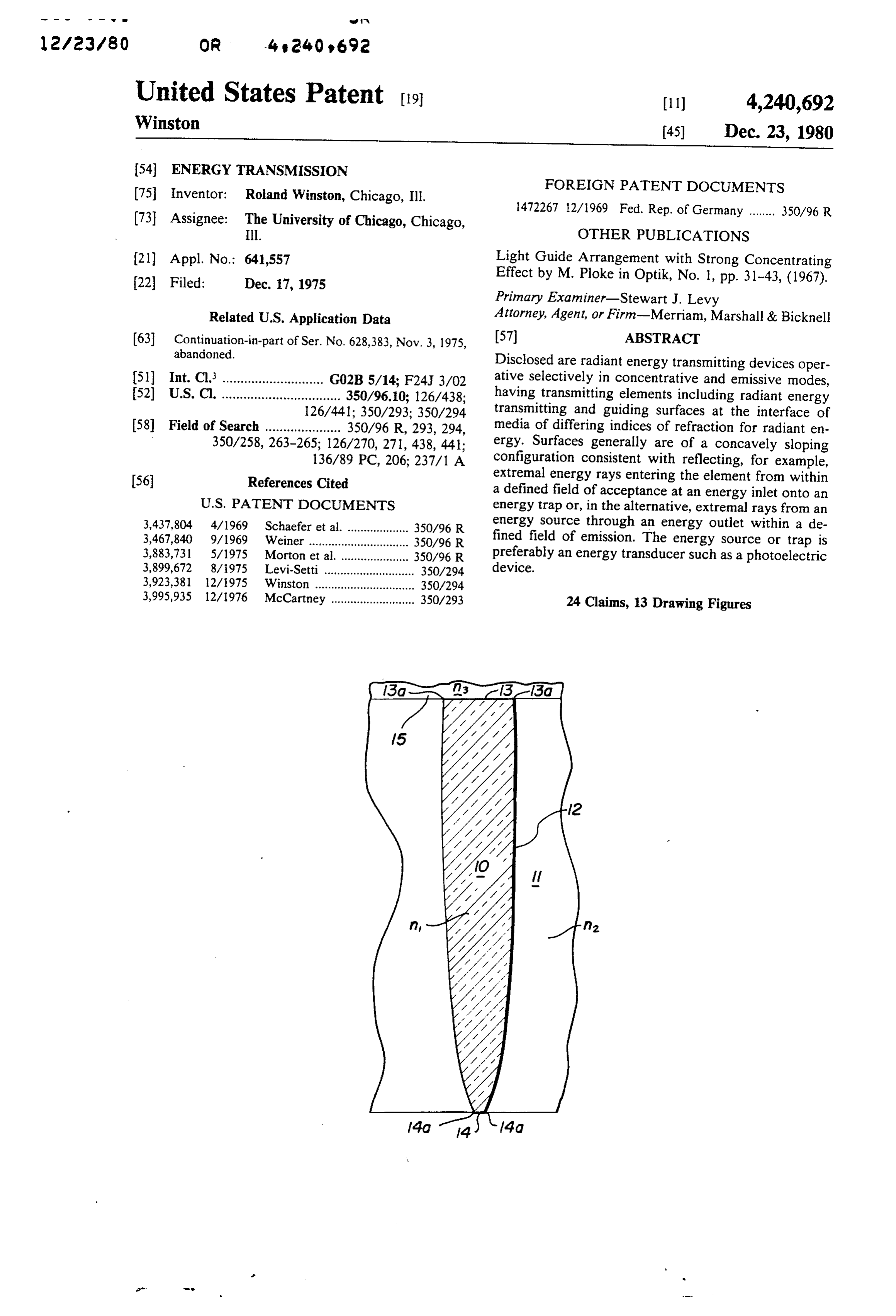
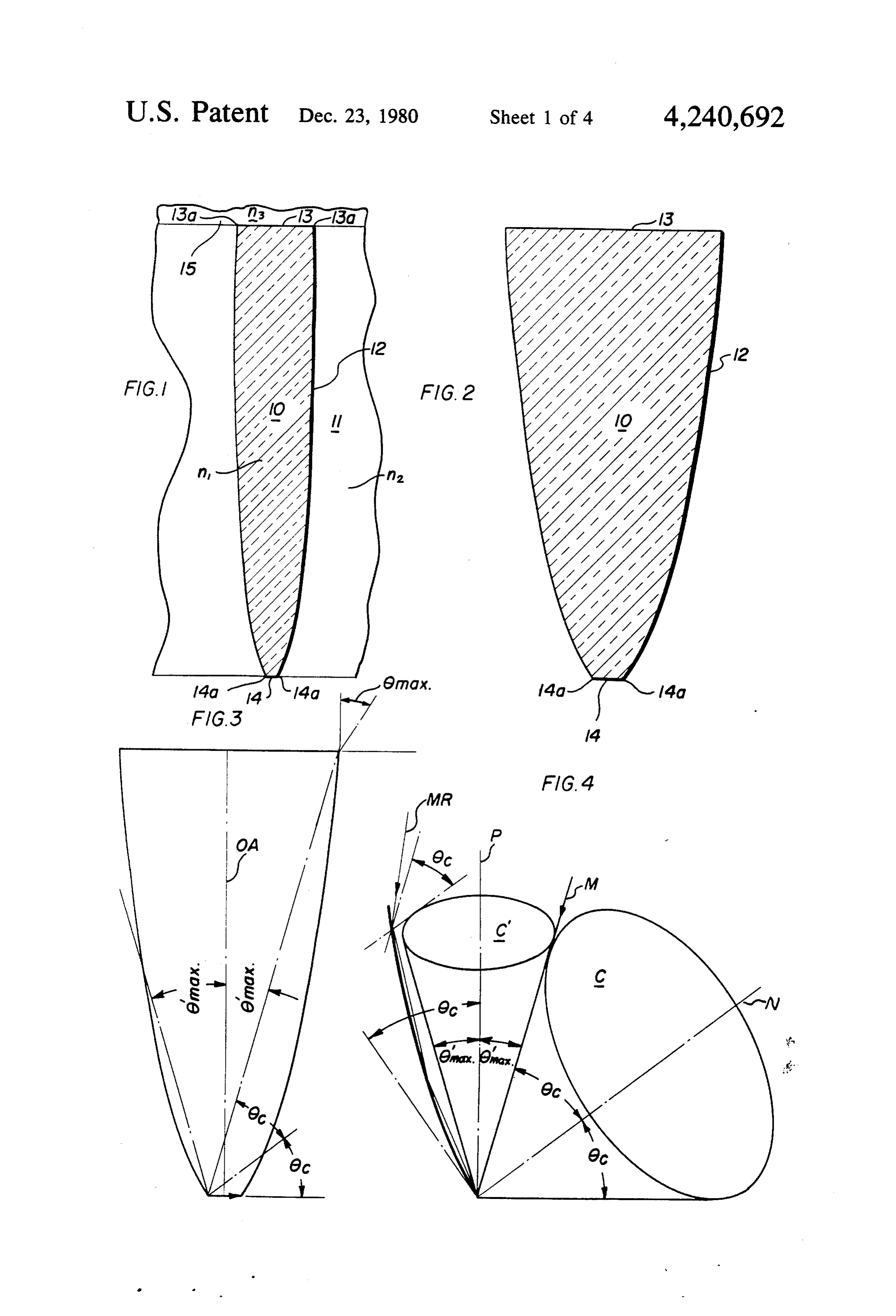
BRIEF DESCRIPTION FIG. 2 illustrates the lower one quarter portion of the According to the present invention apparatus is pro radiant energy transmitting element of FIG. 1; FIG. 3 is a schematic cross-sectional view of another vided for use in an external radiant energy transmitting embodiment of a radiant energy transmitting element of medium and selectively constructed for operation in 5 the invention;
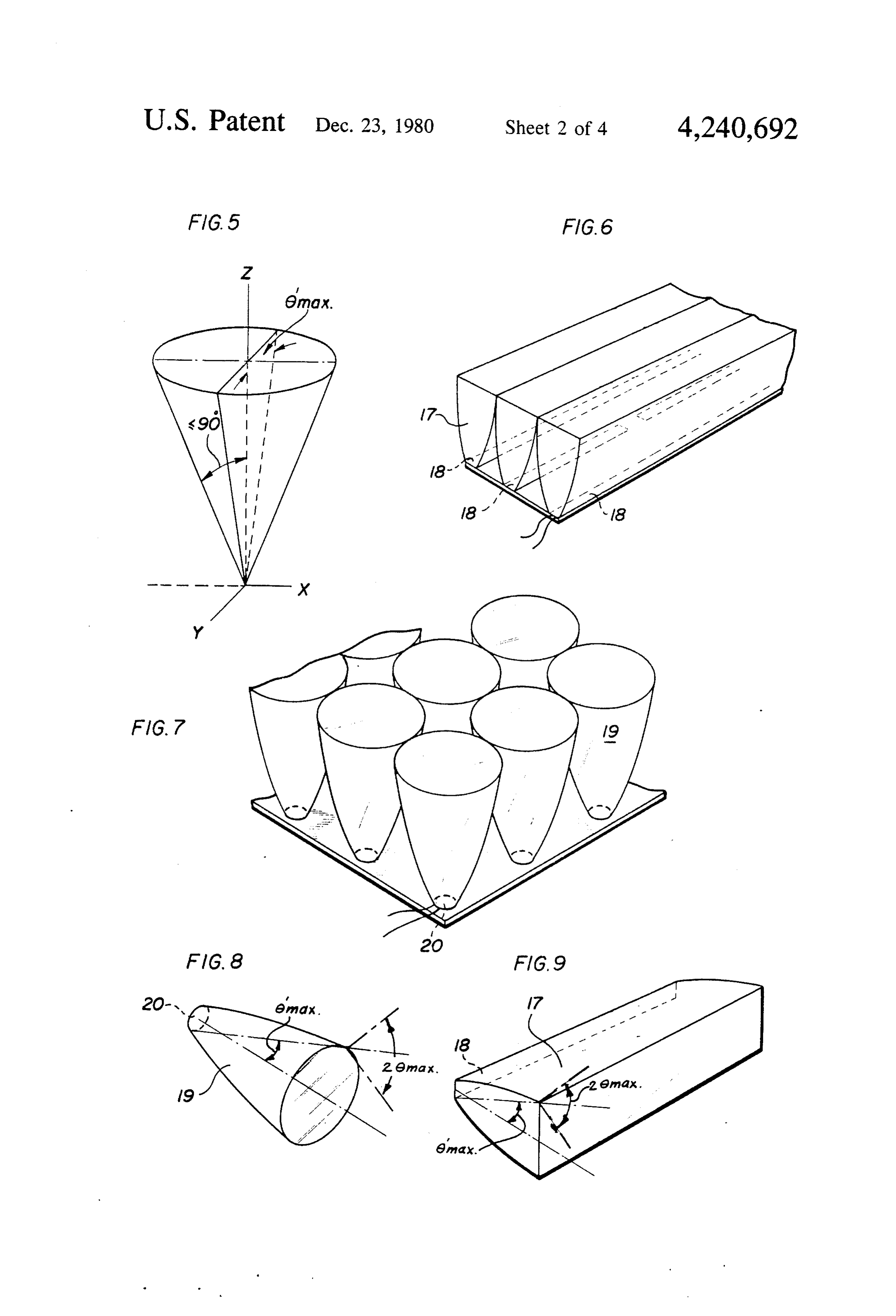
concentrative and emissive modes. The structures are of FIG. 4 is a graphic representation of certain operative a configuration generally corresponding to those dis characteristics closed for use in energy concentration and now com as in FIG. 3; of a radiant energy transmitting element monly referred to as Compound Parabolic Concentra FIG. 5 is a further graphic representation of certain tor (CPC) structures See, e.g., "Solar Heating and O operative characteristics illustrated in FIG. 4; Cooling: Engineering, Practical Design and Econom FIG. 6 is an illustrative array of radiant energy trans ics', J. F. Kreider and F. Kreith, McGraw-Hill, New mitting elements of the invention operable in either York (1975) pp. 98-101). concentrative or emissive modes;
For CPC-type devices "filled' with energy transmit FIG. 7 is an illustrative array of alternative embodi ting media one would a priori expect that, due to the 15 ments of radiant energy transmitting elements of the wide variation of internal angles of energy ray inci invention dence with the reflective wall, only a fraction of all rays modes; operable in either concentrative or emissive would be totally reflected in the absence of an exter FIG. 8 is a perspective view of a single radiant energy nally applied reflective coating. The present invention transmitting element of the invention illustrating opera demonstrates the unexpected circumstance that the 20 tion in a emissive and/or concentrative modes; conditions requisite for total internal reflectivity and for construction of CPC-type devices co-exist for cases of ment of a radiant energy view
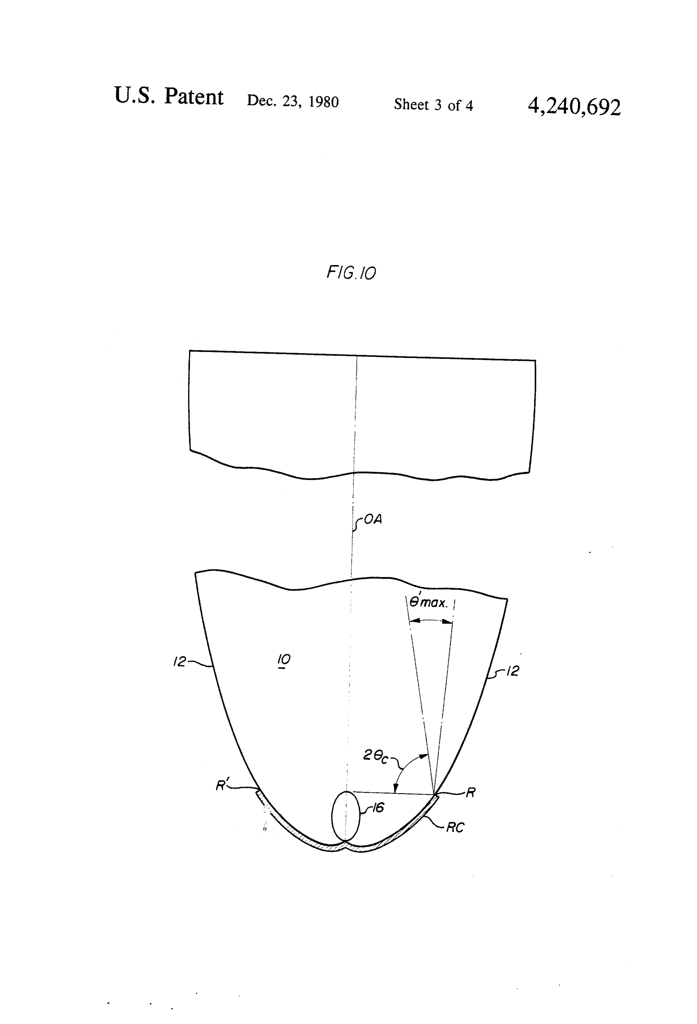
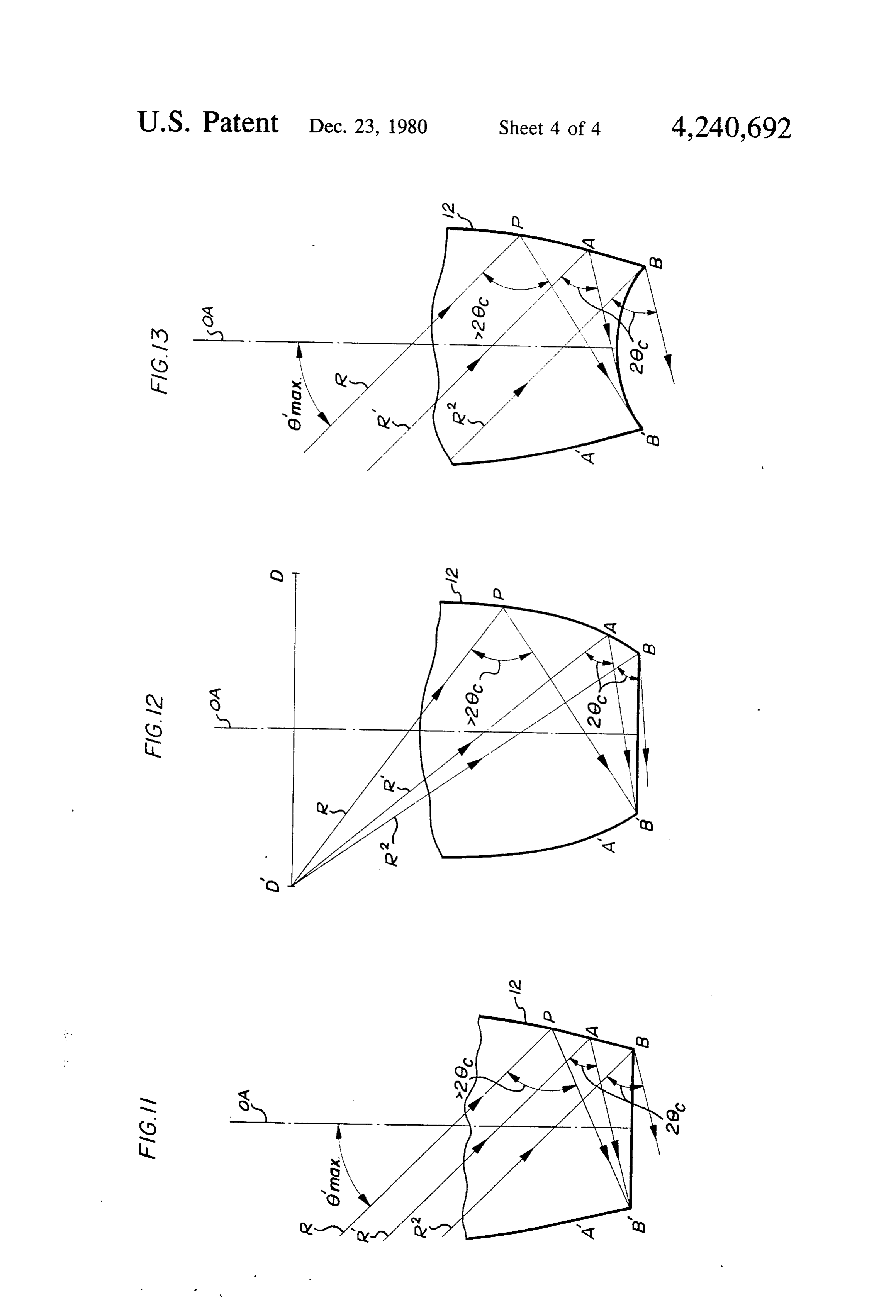
FIG. 9 is a perspective of an alternative embodi transmitting element illustrat considerable practical importance. Apparatus of the ing operation in a emissive and/or concentrative modes; invention includes, in broad aspect, radiant energy FIG. 10 is a sectional view of a cylindrical trough transmitting structures of generally trough-like (cylin 25 like channel of the invention constructed for maximal drical) or conical shape. The structures include a radi concentration of radiant energy onto a tubular energy ant energy inlet (or outlet) which participates in estab receiver or trap and illustrating remedial reflective lishing a field of acceptance (or emission) and energy coating;
reflecting and guiding walls generated at and/or by the FIG. 11 is a schematic cross-sectional view of an interface between the external medium and a medium 30 embodiment of the invention illustrating remedial shap internal of or to the structures. The structures are uti lized in combination with a radiant energy trap (or centration ing of reflective surfaces consistent with maximal con and total internal reflection;
source). The energy reflective walls of the structures FIG. 12 is a schematic cross-sectional view of an are generally concavely sloping in a manner optimally consistent with permitting certain extremal rays, char 35 embodiment ing of of the invention illustrating remedial shap reflective surfaces consistent with maximal con acterized by reference to the field of acceptance (or centration and total internal reflection as particularly emission) to reach or emanate from the energy trap or applicable in concentrative operation for a fixed-dis SOCe.
tance source of radiant energy;
As employed herein, the terms "extremal" has the FIG. 13 is a schematic cross-sectional view of an meaning ordinarily attributable to the term "extreme' embodiment of the invention illustrating remedial shap but also includes the meaning given to the term in the ing of reflective surfaces consistent with maximal con art of the calculus of variations wherein a function is centration and total internal reflection as particularly called an "extremal' when it is a solution to the varia applicable to use of a tubular radiant energy source or tional problem under consideration. trap.
Comprehended by the invention are symmetric and 45 asymmetric transmitting structures combined with en DETAILED DESCRIPTION ergy traps or sources both disposed internally and exter In view of bimodal operative capabilities of apparatus nally of the reflective walls. according to the present invention, the following de Structures of particular interest according to the tailed description shall refer for convenience of under present invention include those wherein the ratio of 50 standing to operational characteristics applicable to use refractive indices of internal to external media is in in radiant energy collection and concentration modes excess of the square root of 2. Also comprehended are although these same operational characteristics, gener transmitting structures substantially totally internally ally directionally reversed, are applicable to use in emis reflective with respect to energy rays of angular interest sive modes. Thus, reference to radiant energy "concen as well as structures with respect to which "remedial' 55 trators' shall include reference to "emitters' and bimo features (such as optical coupling with reflective coat dally operative (e.g., retroreflective) devices unless ings or remedial sloping of reflective wall portions) are otherwise expressly indicated. In keeping with this for provided to assist in the functional approximation of mat, for example, reference to an "inlet' in the course of substantial total internal reflectivity.
Further aspects and advantages of the presnt inven 60 description of concentrative apparatus shall include reference to an "outlet' for emissive structures.
tion will become apparent upon consideration of the As used herein and in the claims, the term "energy following description thereof, reference being made to trap' shall mean and include any apparatus or material the drawing. having the capacity for detection, utilization and/or BRIEF DESCRIPTION OF THE DRAWING 65 term further transmission of radiant energy. As such, the FIG. 1 is a transverse sectional view of a radiant includes, but is not limited to, such radiant energy energy transmitting element of the invention within a cells. As useddevices conversion herein or transducers as photoelectric and in the claims, the term "energy radiant energy transmitting medium; source' shall mean and include any apparatus or mate
Page 8
rial having the capacity to emit or re-emit (e.g., by For clarity, all indices of refraction have been assumed reflection) radiant energy. As such, the term includes, to be identical in the immediately preceding discussion. but is not limited to, such devices as light emitting di The geometric relationships illustrated in FIG. 1 are odes and mirrors. exposed with somewhat greater clarity in FIG. 2 FIG. 1 illustrates in cross-section an embodiment of a wherein only the lower one quarter portion of the 6' concentrative radiant energy transmission element 10 0nax CPC-type structure has been shown. for use in an external radiant energy transmitting me Clearly, relationships shown in the cross-sectional dium 11. As shown, element 10 consists at least in perti views represented by FIGS. 1 and 2 are equally applica nent part of a material which itself is an energy transmit ble to trough-shaped concentrators (see, e.g. FIGS. 6 ting medium having an index of refraction, n, and ex O and 9) as well as to conically-shaped concentrators (see, ternal medium 11 consists of a substance having an e.g. FIGS. 7 and 8).
index of refraction, n2. According to well-known prin It should be additionally noted that the following ciples of fiber optics, in those situations wherein n and description of operative characteristics of trough n2 are unequal, there is formed or generated at the inter shaped CPC-like structures of the variety illustrated in face of these media an optically reflective wall or sur 15 FIGS. 1 through 6 and 9 are equally applicable to vari face 12. In the embodiment illustrated, where n is ant embodiments of ideal cylindrical collectors of greater than n2, the surface 12 is consequently reflective trough-like configuration (e.g. FIGS. 10 and 13) for energy impinging thereon from within element 10. wherein, for example, radiant energy is maximally con Alternatively stated, wall or surface 12 provides inter centrated onto a receiver 16 tubular in general shape nal reflectivity for and within transmission element 10. 20 (including inter alia, those having an elliptical, circular The particular embodiment of FIG. 1 illustrates an or oval cross-section) and wherein the receiver is gener energy transmitting element of a configuration gener ally ally conforming to (CPC) structures useful in energy tweendisposed within the concentrator 10 and/or be reflective wall elements 12, 12 of the concentra concentration. Viewed in consideration of known CPC to.
construction formulations, surface 12 is seen to "origi 25 The CPC-type structures in both trough-like and nate' at, and at least in part define, a radiant energy inlet cone geometries generally can achieve a concentration 13 and also to "terminate' at and similarly define a ratio, x, according to the following.
radiant energy outlet 14 (optimally co-planar with inlet 13). Energy inlet 13 is in optical contact with radiant x = n/sin 6 max (trough), (l) energy transmitting medium 15 having an index of re 30 fraction (n3) which may be the same or different as n x = n/sin,nax (cone), (2) and/or n2. The profile curve reveals a pair of opposed reflective walls or surfaces 12 generally parabolically where 6max is the angular acceptance (half angle) and in concavely sloped to assume the maximum possible slope is the index of refraction of the collector relative to the consistent with reflecting through or onto the energy 35 medium at the energy inlet. Where the trough or cone is outlet 14 (having an energy trap operatively associated air-filled and the inlet is in contact with air, n = 1. This therewith) the extremal energy rays which enter the concentration ratio is believed to be the maximum per energy inlet from within the field of acceptance of the missible by physical principles.
CPC structure. According to the present invention it has-been deter Other general characteristics of CPC configurations mined that for certain values of parameters of consider are equally applicable to the embodiment of FIG. 1. able practical importance, the interface between a me Structures of this type, for example, generally have a dium internal to a CPC-type structure's walls and that well defined field of acceptance for radiant energy, an surrounding (and optically coupled to) the structure's angular acceptance, 6,nax, for such energy within such walls provides a substantially perfect total internally field determinable with respect to the energy inlet, and, 45 reflective surface which prevents or minimizes leakage depending upon the particular embodiment employed, of radiation, thereby obviating the need for e.g., a me an optical axis determinable by reference to distances tallic reflective coating to provide for energy guiding separating opposed "edge' portions of the energy inlet and reflecting.
13 and outlet 14 (designated 13a, 13a and 14a, 14a re Where the internal medium of element 10 has a re spectively). Similarly, the ratio of transverse dimensions 50 fractive index (n1) in excess of the refractive index (n2) of the outlet 14 and inlet 13 of the embodiment is prefer of the external media 11 and 13 (i.e., n2 = n3) in contact ably not less than the sine of the angular acceptance of therewith, incident rays which lie within the angular the CPC structure. The parabolic curvature of the re acceptance (6ma) of a trough-shaped CPC-type struc flective wall 12 has as its focus the opposing "edge' of ture are refracted into an elliptic cone of semi-minor the energy outlet 14 and as its axis a line forming an 55 angle 6'na and semi-major angle 6 where angle with the optical axis equal to the angular accpe tance, gnar. The overall height of the embodiment is n = n/n2 = relative refractive index (3) preferably equal to half the product of the sum of the sin 6"max= (l/n) sin 6max, and (4) transverse dimensions of inlet 13 and outlet 14 multi plied by the cotangent of the angular acceptance, 6max. 0=arcsin (l/n), the critical angle. (5) Clearly some substantial truncation of the concentrator may be made for practical (i.e., ease of fabrication) For the cone-shaped CPC-type structures the angular purposes with corresponding loss of concentrative ca range is simply a cone of half angle 6'max. pacity though without diminution of angular accep These rays are funnelled to the exit aperture after tance. Similarly, the effective energy inlet may be "ex 65 perhaps one or more reflections. In order for a ray to tended' or "relocated' by linearly extending wall 12 undergo total internal reflection at the wall, it must lie parallely to the optic axis without substantial alteration outside the critical cone of half angle 6. For the trough of the angular acceptance of the concentrator element. and perhaps also the cone, the severest test of this con
Page 9
dition occurs for the extreme meridional ray incident on number of reflections are substantially internally re the exit edge of the reflecting wall (see FIG. 4). Then, flected.
the condition becomes According to the relationships above-described, if the sin 8'nars (1-2/n') (6) 6"max = 17.94 structure of FIG. 3 were of a trough shaped CPC-type, filled with a uniform medium so that wherein n1 = 1.7, and in optical contact with air (n2 = 1) both at wall 12 and at inlet 13 (i.e., n3 = n.2), then 8a.
sin 9muren (1-2/n) (7) (the angular acceptance of the concentrator element) would be equal to 31.57 and the concentration capabil xmax = 1/(1-2/n) (trough) (8) O ity would be up to 3.25.
Table 1, following, graphically provides certain rela
Ana = 1/(1-2/n)' (cone) (9) tionships for trough-shaped CPC-type concentrators of varying parameters.
Notice that at sine 6,na = 1, equation 7 has the solution 5 TABLE 1 22, so that n=2 achieves a full 180° field of view. n 6"max 6max Concentration'" Alternatively where n = V2 a field of view approaching -O -O - 0 is achieved.
These relationships will be better understood through 5 6.38 9.59 9.00 consideration of FIGS. 3, 4 and 5. FIG. 3 illustrates a 20 1.6
cross-sectional view of a CPC-type structure (of either 8 22.50 43.54 2.61 trough-like or conical geometry) according to the in 9 26.49 57.93 2.24 vention wherein 6'na, the angular acceptance within 20 30.00 90.00 2.00 the medium filling the concentrator, is approximately **Concentration n = n/n3 = relative refractive index
17.941. (Note that for ease of illustration and demon 25 stration the following are assumed: that the medium The concentration capability of CPC-type conical filling the concentrator element 10 is uniform through concentrators will, of course, approach 1/(sin 8'na) as out; and that the medium 11 external to wall or surface opposed to 1/sin 6'nax for troughs. 12 is of identical refractive index to that medium 15 in optical contact with energy inlet 13, i.e., that n2 = n3). 30 is When an index of refraction ration). 2 is available, it possible to increase the concentration by lowering
Line OA designates the optical axis of the element. 0 is 6"na below at 30 while maintaining the 6na = 90° the critical angle, measured with respect to the normal acceptance
N to the interface surface. Radiation impinging at an transmittingcondition. materials
(In infrared applications energy commonly have indices of refrac gles greater than or equal to 6 is consequently totally tion in excess of 2.)
internally reflected. 35
The relationships set out in Table 1 represent the
Application of this property is illustrated in FIG. 4 largest angular acceptances obtainable for particular wherein M represents the extreme meridional ray values of the variable in when the range of its values is above-discussed. For either trough-shaped or conical from V2 to 2, which varies almost serendipitously cor CPC-type concentrators, radiant energy impinging respond quite well to the indices of refraction of most upon point 14a outside of the cone C defined by axis N "transparent' solids relative to the refractivity of air. and half angle 8 is totally internally reflected. It is Clearly, configurations employing smaller values of therefore seen that any ray impinging from within the 6'nax may be constructed with resultant enhancement of field of acceptacne (within cone C') is reflected toward concentrative capability and, of course, without loss of or through outlet 14. For a CPC-type concentrator of the total internal reflective capability. Thus, for exam conical geometry, cone C' is a right circular cone hav 5 ple, a trough-shaped CPC-type concentrator filled with ing as its axis line P, parallel to the optic axis and a half an acrylic plastic medium having n ~ 1.5 (where me angle equal to 6'na. For a CPC-type concentrator of dium 11 is air) may be constructed to assume a value of trough-like geometry, cone C' is as represented in FIG. 6'na of 3, in which case 6max= 4.5 and the maximum 5, i.e., an elliptic cone having as its semi-minor angle concentrative capability approaches 19.00. In a like 6"na and as its semi-major angle 6. Note, for example, 50 manner, through use of a glass-filled (n - 1.6) a concen that if inlet 13 is in optical contact with a medium 15 trator with 6' = 6.00 will result in 6 = 9.63 and differing in refractive index from that in contact with provide a maximum concentrative capability of about surface 12, (i.e., n3-7-n2) the semi-major angle of cone C 9.57. Note that these values indicate an exceptional may vary and approach 90. 55 flexibility in constructing transmission elements for
Having satisfied the total internal reflection condition solar energy concentration without diurnal tracking. at point 14a, it is apparent that this condition is also met For the case wherein the medium 15 in optical at points along wall 12 closer to the inlet. Multiple contact with the energy inlet 13 has a different index of reflections in CPC-type trough-shaped concentrators, refraction from that in contact with and surrounding including those of skew rays, will occur only off the 60 wall 12 (n3 /-n2), all previous statements of relationships same wall and obviously satisfy the condition (see, e.g., apply, with the modifivation that 6max should be com rays illustrated along line MR). Multiple reflections of puted in accordance with the following: meridional rays in a CPC-type conical concentrator sin 8max = (n1/n3) sin 8"max (10) also occur only off the same wall profile and similarly satisfy the condition. Skew rays in a CPC-type conical 65 For those cases wherein the medium filling concen collector are obviously seen to satisfy the total internal trator 10 is non-uniform, adjustments in angular proper reflection condition up to and including two reflections. ties consistent with known theories of fiber optics will A ray trace reveals that all skew rays, irrespective of the apply.
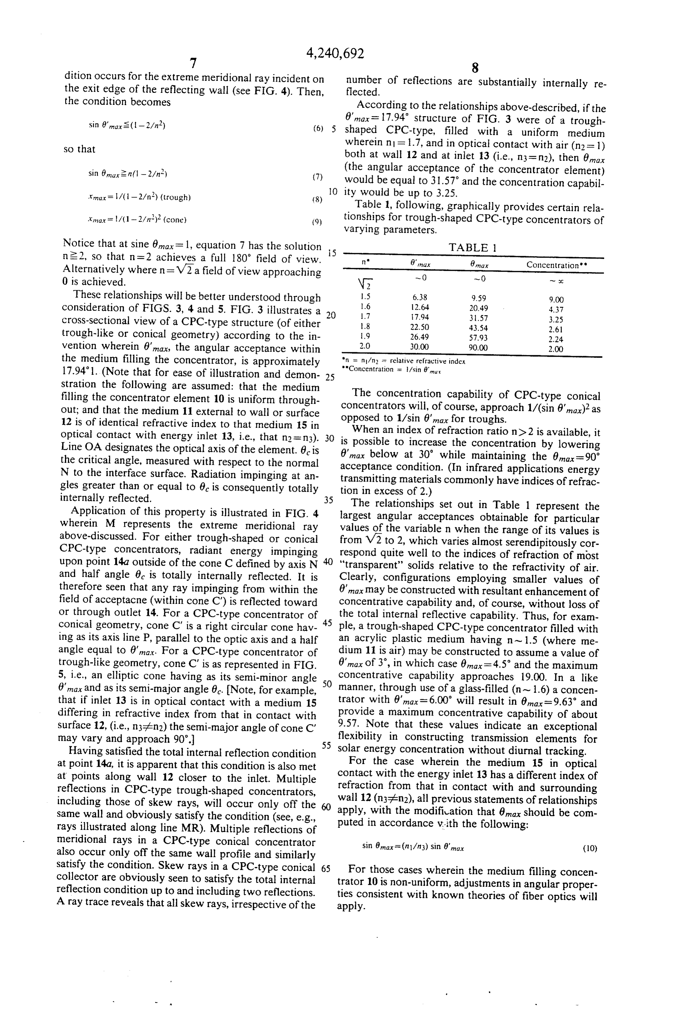
Page 10
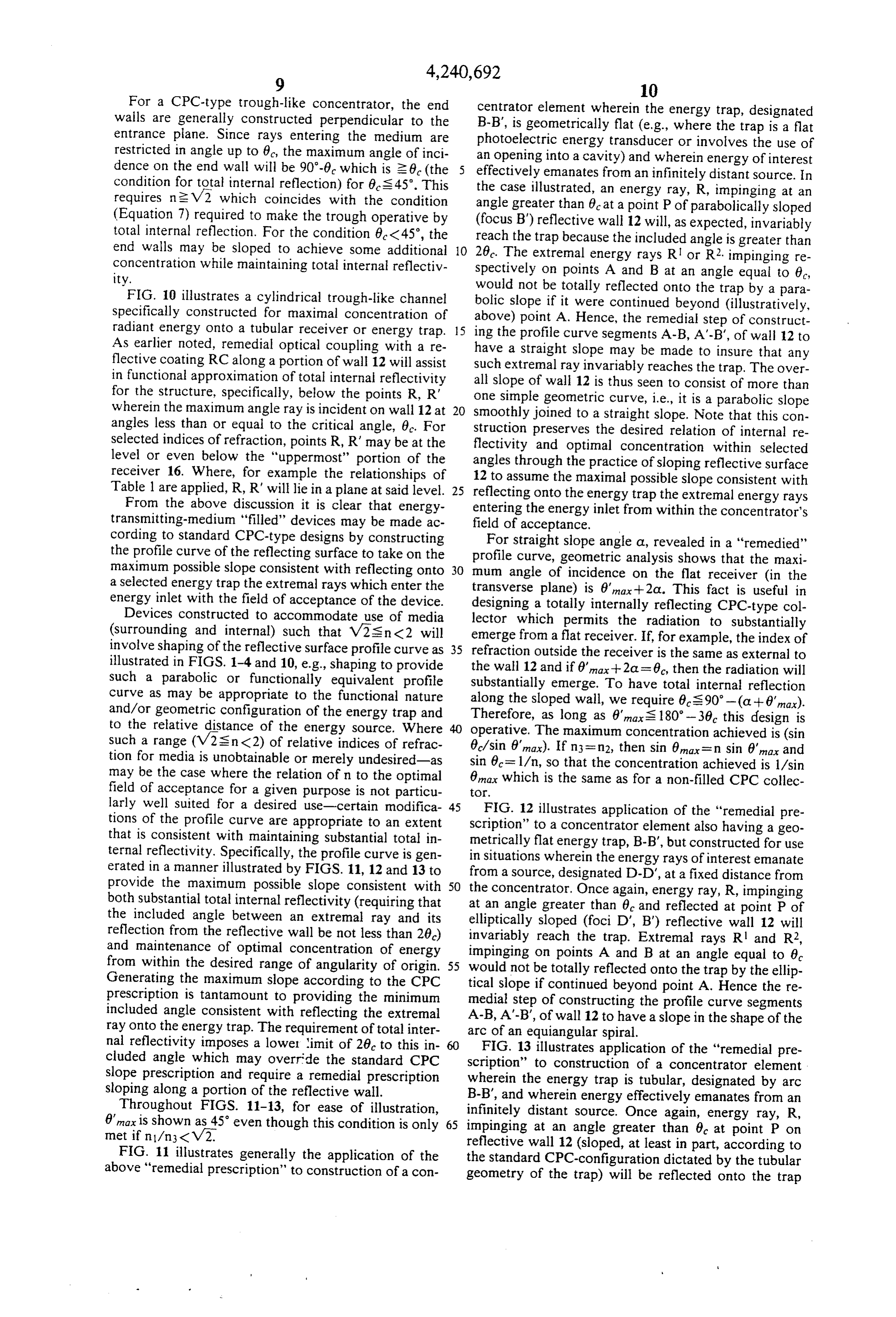
For a CPC-type trough-like concentrator, the end centrator element wherein the energy trap, designated walls are generally constructed perpendicular to the B-B', is geometrically flat (e.g., where the trap is a flat entrance plane. Since rays entering the medium are photoelectric energy transducer or involves the use of restricted in angle up to 6c, the maximum angle of inci an opening into a cavity) and wherein energy of interest dence on the end wall will be 90'-0 which is 26 (the effectively emanates from an infinitely distant source. In condition for total internal reflection) for 6's 45. This the case illustrated, an energy ray, R, impinging at an requires neV2 which coincides with the condition angle greater than 6e at a point P of parabolically sloped (Equation 7) required to make the trough operative by (focus B") reflective wall 12 will, as expected, invariably total internal reflection. For the condition 0 <45, the reach the trap because the included angle is greater than end walls may be sloped to achieve some additional O 26. The extremal energy rays R or R2, impinging re concentration while maintaining total internal reflectiv spectively on points A and B at an angle equal to 0,
FIG. 10 illustrates a cylindrical trough-like channel bolic would not be totally reflected onto the trap by a para slope if it were continued beyond (illustratively, specifically constructed for maximal concentration of above) point A. Hence, the remedial step of construct radiant energy onto a tubular receiver or energy trap. 15 ing the profile curve segments A-B, A'-B', of wall 12 to As earlier noted, remedial optical coupling with a re have a straight slope may be made to insure that any flective coating RC along a portion of wall 12 will assist such extremal ray invariably reaches the trap. The over in functional approximation of total internal reflectivity all slope of wall 12 is thus seen to consist of more than for the structure, specifically, below the points R, R' one simple geometric curve, i.e., it is a parabolic slope wherein the maximum angle ray is incident on wall 12 at 20 smoothly joined to a straight slope. Note that this con angles less than or equal to the critical angle, 6c. For struction preserves the desired relation of internal re selected indices of refraction, points R, R' may be at the flectivity and optimal concentration within selected level or even below the "uppermost' portion of the angles through the practice of sloping reflective surface receiver 16. Where, for example the relationships of 12 to assume the maximal possible slope consistent with Table 1 are applied, R, R' will lie in a plane at said level. 25 reflecting onto the energy trap the extremal energy rays From the above discussion it is clear that energy entering the energy inlet from within the concentrator's transmitting-medium "filled" devices may be made ac field of acceptance.
cording to standard CPC-type designs by constructing the profile curve of the reflecting surface to take on the profile straight
For slope angle a, revealed in a "remedied" curve, geometric analysis shows that the maxi maximum possible slope consistent with reflecting onto 30 mum angle of incidence on the flat receiver (in the a selected energy trap the extremal rays which enter the transverse energy inlet with the field of acceptance of the device. designing aplane) is 6'max+2a. This fact is useful in totally internally reflecting CPC-type col
Devices constructed to accommodate use of media lector which permits the radiation to substantially (surrounding and internal) such that V2s n <2 will emerge from a flat receiver. If, for example, the index of involve shaping of the reflective surface profile curve as 35 refraction outside the receiver is the same as external to illustrated in FIGS. 1-4 and 10, e.g., shaping to provide the wall 12 and if 6'na. --2a = 6c, then the radiation will such a parabolic or functionally equivalent profile substantially emerge. To have total internal reflection curve as may be appropriate to the functional nature along the sloped wall, we require 6S 90-(a + 6'na). and/or geometric configuration of the energy trap and Therefore, as long as 8"mas 180°-36 this design is to the relative distance of the energy source. Where operative. The maximum concentration achieved is (sin such a range (V2s n < 2) of relative indices of refrac 6/sin 8"max). If n3 = n2, then sin 6max = n sin 6'max and tion for media is unobtainable or merely undesired-as sin 6 = 1/n, so that the concentration achieved is 1/sin may be the case where the relation of n to the optimal 8m which is the same as for a non-filled CPC collec field of acceptance for a given purpose is not particu tor.
larly well suited for a desired use-certain modifica 45 FIG. 12 illustrates application of the "remedial pre tions of the profile curve are appropriate to an extent scription' to a concentrator element also having a geo that is consistent with maintaining substantial total in ternal reflectivity. Specifically, the profile curve is gen metrically flat energy trap, B-B', but constructed for use in situations wherein the energy rays of interest emanate erated in a manner illustrated by FIGS. 11, 12 and 13 to from a source, designated D-D', at a fixed distance from provide the maximum possible slope consistent with 50 the concentrator. Once again, energy ray, R, impinging both substantial total internal reflectivity (requiring that at an angle greater than 6 and reflected at point P of the included angle between an extremal ray and its elliptically sloped (foci D', B) reflective wall 12 will reflection from the reflective wall be not less than 20) invariably reach the trap. Extremal rays R and R2, and maintenance of optimal concentration of energy impinging on points A and B at an angle equal to 6 from within the desired range of angularity of origin. 55 would not be totally reflected onto the trap by the ellip Generating the maximum slope according to the CPC tical slope if continued beyond point A. Hence the re prescription is tantamount to providing the minimum medial step of constructing the profile curve segments included angle consistent with reflecting the extremal A-B, A'-B', of wall 12 to have a slope in the shape of the ray onto the energy trap. The requirement of total inter arc of an equiangular spiral.
nal reflectivity imposes a lower limit of 26c to this in FIG. 13 illustrates application of the "remedial pre cluded angle which may override the standard CPC scription' slope prescription and require a remedial prescription wherein thetoenergy construction of a concentrator element trap is tubular, designated by arc sloping along a portion of the reflective wall. B-B', and wherein energy effectively emanates from an Throughout FIGS. 11-13, for ease of illustration, infinitely distant source. Once again, energy ray, R, 6"max is shown as 45 even though this condition is only 65 impinging at an angle greater than 6 at point P on met if n/n3 <V2. reflective wall 12 (sloped, at least in part, according to FIG. 11 illustrates generally the application of the the standard CPC-configuration dictated by the tubular above "remedial prescription' to construction of a con geometry of the trap) will be reflected onto the trap
Page 11
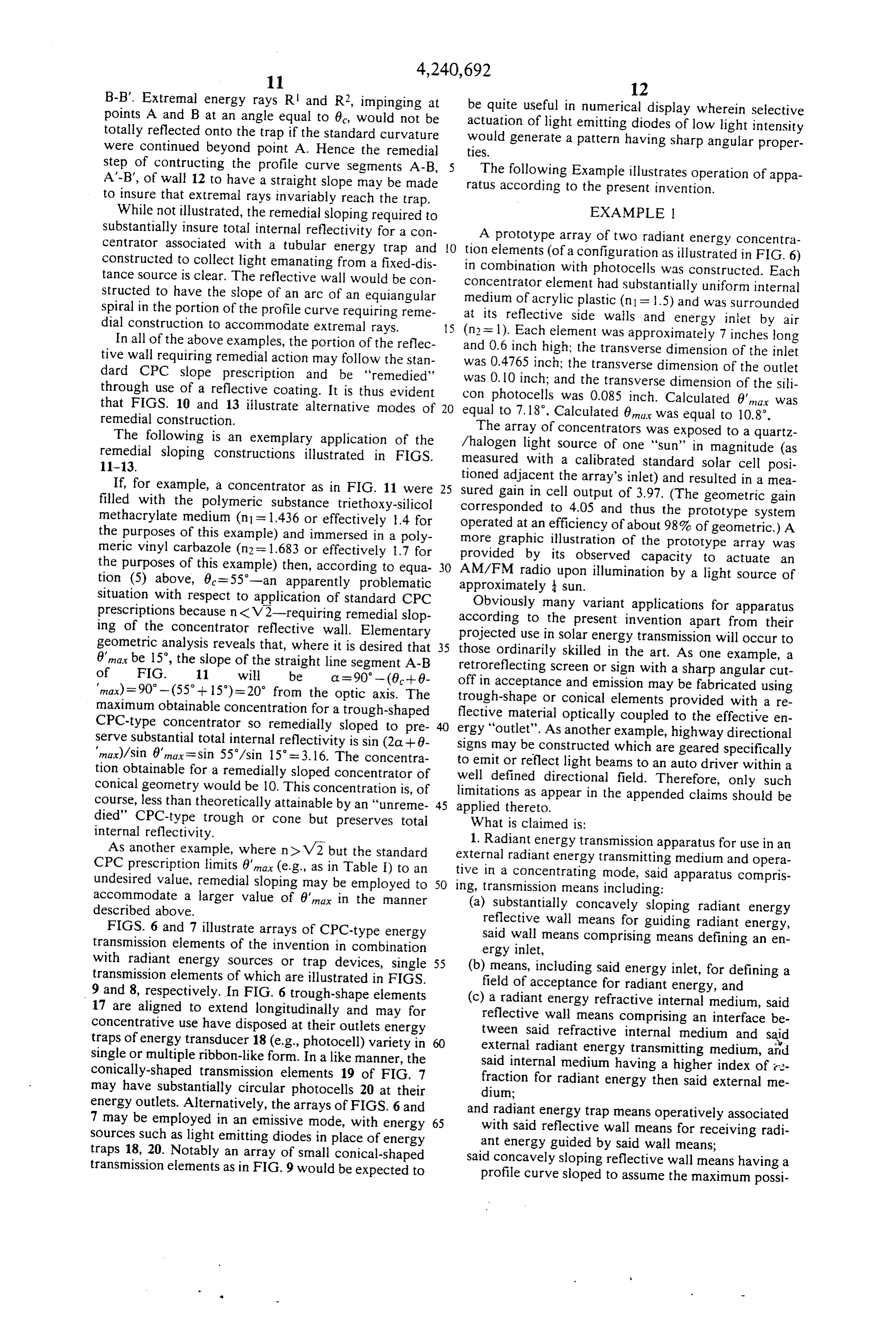
B-B'. Extremal energy rays R and R2, impinging at 12 points A and B at an angle equal to 6c, would not be be quite useful in numerical display wherein selective totally reflected onto the trap if the standard curvature actuation of light emitting diodes of low light intensity were continued beyond point A. Hence the remedial ties. would generate a pattern having sharp angular proper step of contructing the profile curve segments A-B, The following Example illustrates operation of appa A'-B', of wall 12 to have a straight slope may be made ratus according to the present invention. to insure that extremal rays invariably reach the trap.
While not illustrated, the remedial sloping required to EXAMPLE 1 substantially insure total internal reflectivity for a con A prototype array of two radiant energy concentra centrator associated with a tubular energy trap and O tion elements (of a configuration as illustrated in FIG. 6) constructed to collect light emanating from a fixed-dis in combination with photocells was constructed. Each tance source is clear. The reflective wall would be con structed to have the slope of an arc of an equiangular medium of acrylic plastic (n = 1.5) and uniform concentrator element had substantially was internal surrounded spiral in the portion of the profile curve requiring reme at its reflective side walls and energy inlet by air dial construction to accommodate extremal rays. S (n2 = 1). Each element was approximately 7 inches long In all of the above examples, the portion of the reflec and tive wall requiring remedial action may follow the stan was 0.6 inch high; the transverse dimension of the inlet 0.4765 inch; the transverse dimension of the outlet dard CPC slope prescription and be "remedied' was 0.10 inch;
through use of a reflective coating. It is thus evident con photocellsand the transverse dimension of the sili was 0.085 inch. Calculated 6', a was that FIGS. 10 and 13 illustrate alternative modes of equal to 7. 18. Calculated 6,na was equal to 10.8. remedial construction.
The following is an exemplary application of the /halogen The array of concentrators was exposed to a quartz remedial
sloping constructions illustrated in FIGS. measured light source of one 'sun' in magnitude (as with a calibrated standard solar cell posi
If, for example, a concentrator as in FIG. 11 were 25 suredtioned adjacent the array's inlet) and resulted in a nea filled with the polymeric substance triethoxy-silicol corresponded gain in cell output of 3.97. (The geometric gain methacrylate medium (n1 = 1.436 or effectively 1.4 for operated at an efficiency to 4.05 and thus the prototype system the purposes of this example) and immersed in a poly more graphic illustrationofofabout the 98% of geometric.) A prototype array was meric vinyl carbazole (n2 = 1.683 or effectively 1.7 for provided by its observed capacity the purposes of this example) then, according to equa 30 AM/FM radio upon illumination by a to actuate an light source of tion (5) above, 6 c = 55'-an apparently problematic approximately sun.
situation with respect to application of standard CPC Obviously many variant applications for apparatus prescriptions because n <V2-requiring remedial slop according to the present invention apart from their ing of the concentrator reflective wall. Elementary projected use in solar energy transmission will occur to geometric analysis reveals that, where it is desired that 35 those ordinarily skilled in the art. As one example, a 6"may be 15, the slope of the straight line segment A-B retroreflecting screen or sign with a sharp angular cut of FIG. 11 will be a = 90 - (0--0- off in acceptance and emission may be fabricated using "ma)=90-(55-15)=20 from the optic axis. The trough-shape or conical elements maximum obtainable concentration for a trough-shaped flective material optically coupledprovided to the with a re effective en
CPC-type concentrator so remedially sloped to pre ergy "outlet'. As another example, highway directional serve substantial total internal reflectivity is sin (2a-6- signs na)/sin 6"max=sin 55/sin 15 = 3.16. The concentra to emitmay or be constructed which are geared specifically reflect light beams to an auto driver within a tion obtainable for a remedially sloped concentrator of well defined directional field. Therefore, only such conical geometry would be 10. This concentration is, of limitations as appear in the appended claims should be course, less than theoretically attainable by an "unreme 45 applied thereto.
died" CPC-type trough or cone but preserves total What is claimed is:
internal reflectivity.
As another example, where n> V2 but the standard external 1. Radiant energy transmission apparatus for use in an CPC prescription limits 6'nax (e.g., as in Table I) to an tive in aradiant energy transmitting medium and opera concentrating mode, said apparatus compris undesired value, remedial sloping may be employed to 50 ing, transmission means including: accommodate a larger value of 6"max in the manner (a) substantially concavely sloping radiant energy described above.
FIGS. 6 and 7 illustrate arrays of CPC-type energy reflective wall means for guiding radiant energy, transmission elements of the invention in combination said wall means comprising means defining an en ergy inlet, with radiant energy sources or trap devices, single 55 (b) means, including said energy inlet, for defining a transmission elements of which are illustrated in FIGS. field of acceptance for radiant energy, and 9 and 8, respectively. In FIG. 6 trough-shape elements (c) a radiant energy refractive internal medium, said 17 are aligned to extend longitudinally and may for reflective wall means comprising an interface be concentrative use have disposed at their outlets energy tween said refractive internal medium and said traps of energy transducer 18 (e.g., photocell) variety in external radiant energy transmitting medium, and single or multiple ribbon-like form. In a like manner, the said internal medium having a higher index of re conically-shaped transmission elements 19 of FIG. 7 fraction for radiant energy then said external me may have substantially circular photocells 20 at their dium;
energy outlets. Alternatively, the arrays of FIGS. 6 and and radiant energy trap means operatively associated 7 may be employed in an emissive mode, with energy 65 with said reflective wall means for receiving radi sources such as light emitting diodes in place of energy ant energy guided by said wall means; traps 18, 20. Notably an array of small conical-shaped said concavely sloping reflective wall means having a transmission elements as in FIG.9 would be expected to profile curve sloped to assume the maximum possi
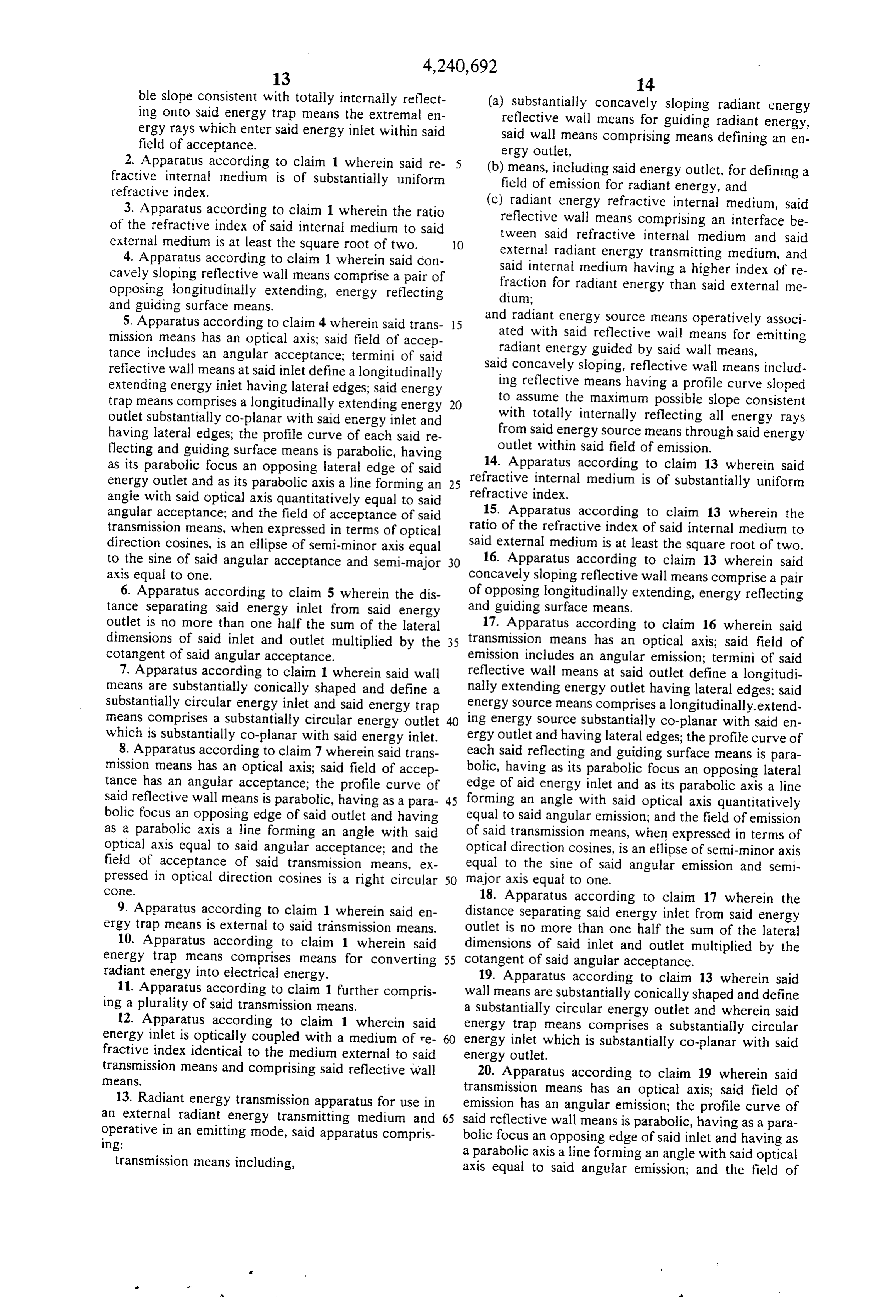
Page 12
ble slope consistent with totally internally reflect (a) substantially concavely sloping radiant energy ing onto said energy trap means the extremal en reflective wall means for guiding radiant energy, ergy rays which enter said energy inlet within said said wall means comprising means defining an en field of acceptance. ergy outlet, 2. Apparatus according to claim 1 wherein said re (b) means, including said energy outlet, for defining a fractive internal medium is of substantially uniform field of emission for radiant energy, and refractive index.
3. Apparatus according to claim 1 wherein the ratio (c) radiant energy refractive internal medium, said of the refractive index of said internal medium to said reflective wall means comprising an interface be external medium is at least the square root of two. tween said refractive internal medium and said
4. Apparatus according to claim 1 wherein said con external radiant energy transmitting medium, and cavely sloping reflective wall means comprise a pair of said internal medium having a higher index of re opposing longitudinally extending, energy reflecting fraction for radiant energy than said external me and guiding surface means. dium;
5. Apparatus according to claim 4 wherein said trans 15 and radiant energy source means operatively associ mission means has an optical axis; said field of accep ated with said reflective wall means for emitting tance includes an angular acceptance; termini of said radiant energy guided by said wall means, reflective wall means at said inlet define a longitudinally said concavely sloping, reflective wall means includ extending energy inlet having lateral edges; said energy ing reflective means having a profile curve sloped trap means comprises a longitudinally extending energy 20 to assume the maximum possible slope consistent outlet substantially co-planar with said energy inlet and with totally internally reflecting all energy rays having lateral edges; the profile curve of each said re from said energy source means through said energy flecting and guiding surface means is parabolic, having outlet within said field of emission. as its parabolic focus an opposing lateral edge of said 14. Apparatus according to claim 13 wherein said energy outlet and as its parabolic axis a line forming an 25 refractive internal medium is of substantially uniform angle with said optical axis quantitatively equal to said refractive index.
angular acceptance; and the field of acceptance of said 15. Apparatus according to claim 13 wherein the transmission means, when expressed in terms of optical ratio of the refractive index of said internal medium to direction cosines, is an ellipse of semi-minor axis equal said external medium is at least the square root of two. to the sine of said angular acceptance and semi-major 30 16. Apparatus according to claim 13 wherein said axis equal to one. concavely sloping reflective wall means comprise a pair 6. Apparatus according to claim 5 wherein the dis of opposing longitudinally extending, energy reflecting tance separating said energy inlet from said energy and guiding surface means.
outlet is no more than one half the sum of the lateral 17. Apparatus according to claim 16 wherein said dimensions of said inlet and outlet multiplied by the 35 transmission means has an optical axis; said field of cotangent of Said angular acceptance. emission includes an angular emission; termini of said 7. Apparatus according to claim 1 wherein said wall reflective wall means at said outlet define a longitudi means are substantially conically shaped and define a nally extending energy outlet having lateral edges; said Substantially circular energy inlet and said energy trap energy source means comprises a longitudinally-extend means comprises a substantially circular energy outlet ing energy source substantially co-planar with said en which is substantially co-planar with said energy inlet. ergy outlet and having lateral edges; the profile curve of 8. Apparatus according to claim 7 wherein said trans each said reflecting and guiding surface means is para mission means has an optical axis; said field of accep bolic, having as its parabolic focus an opposing lateral tance has an angular acceptance; the profile curve of edge of aid energy inlet and as its parabolic axis a line said reflective wall means is parabolic, having as a para 45 forming an angle with said optical axis quantitatively bolic focus an opposing edge of said outlet and having equal to said angular emission; and the field of emission as a parabolic axis a line forming an angle with said of said transmission means, when expressed in terms of optical axis equal to said angular acceptance; and the optical direction cosines, is an ellipse of semi-minor axis field of acceptance of said transmission means, ex equal to the sine of said angular emission and semi pressed in optical direction cosines is a right circular 50 major axis equal to one.
COe.
18. Apparatus according to claim 17 wherein the 9. Apparatus according to claim 1 wherein said en distance separating said energy inlet from said energy ergy trap means is external to said transmission means. outlet is no more than one half the sum of the lateral 10. Apparatus according to claim 1 wherein said dimensions of said inlet and outlet multiplied by the energy trap means comprises means for converting 55 cotangent of said angular acceptance.
radiant energy into electrical energy. 19. Apparatus according to claim 13 wherein said 11. Apparatus according to claim 1 further compris wall means are substantially conically shaped and define ing a plurality of said transmission means. a substantially circular energy outlet and wherein said 12. Apparatus according to claim 1 wherein said energy trap means comprises a substantially circular energy inlet is optically coupled with a medium of re energy inlet which is substantially co-planar with said fractive index identical to the medium external to said energy outlet.
transmission eaS.
means and comprising said reflective wall 20. Apparatus according to claim 19 wherein said transmission 13. Radiant energy transmission apparatus for use in emission has an means has an optical axis; said field of an external radiant energy transmitting medium and 65 said reflective wall angular emission; the profile curve of operative in an emitting mode, said apparatus compris bolic focus an opposing means is parabolic, having as a para ing: edge of said inlet and having as transmission means including, a parabolic axis a line forming an angle with said optical axis equal to said angular emission; and the field of
Page 13
emission of said transmission means, expressed in optical 23. Apparatus according to claim 13 further compris direction cosines is a right circular cone. ing a plurality of said transmission means. 21. Apparatus according to claim 13 wherein said 24. Apparatus according to claim 13 wherein said energy source means is external to said transmission energy outlet is optically coupled with a medium of leaS. refractive index identical to the medium external to said 22. Apparatus according to claim 13 wherein said transmission means and comprising said reflective wall energy source means comprises means for converting leanS.
electrical energy into radiant energy. k xx k is

Provenance
- Collection
- Cited prior art
- Original PDF
- patentimages.storage.googleapis.com →
- Filed
- 1975-12-17
- Pages
- 13
- Method
- pdftotext (the PDF's own text layer) + pdftoppm 300dpi page scans
- Source
- Google Patents bibliographic record
- Granted
- 1980-12-23
- Inventors
- Roland Winston; University of Chicago
- Transcribed from
- patentimages.storage.googleapis.com →