patent · US4697867
Multi-directional non-imaging radiations concentrator and/or deconcentrator device
6 October 1987
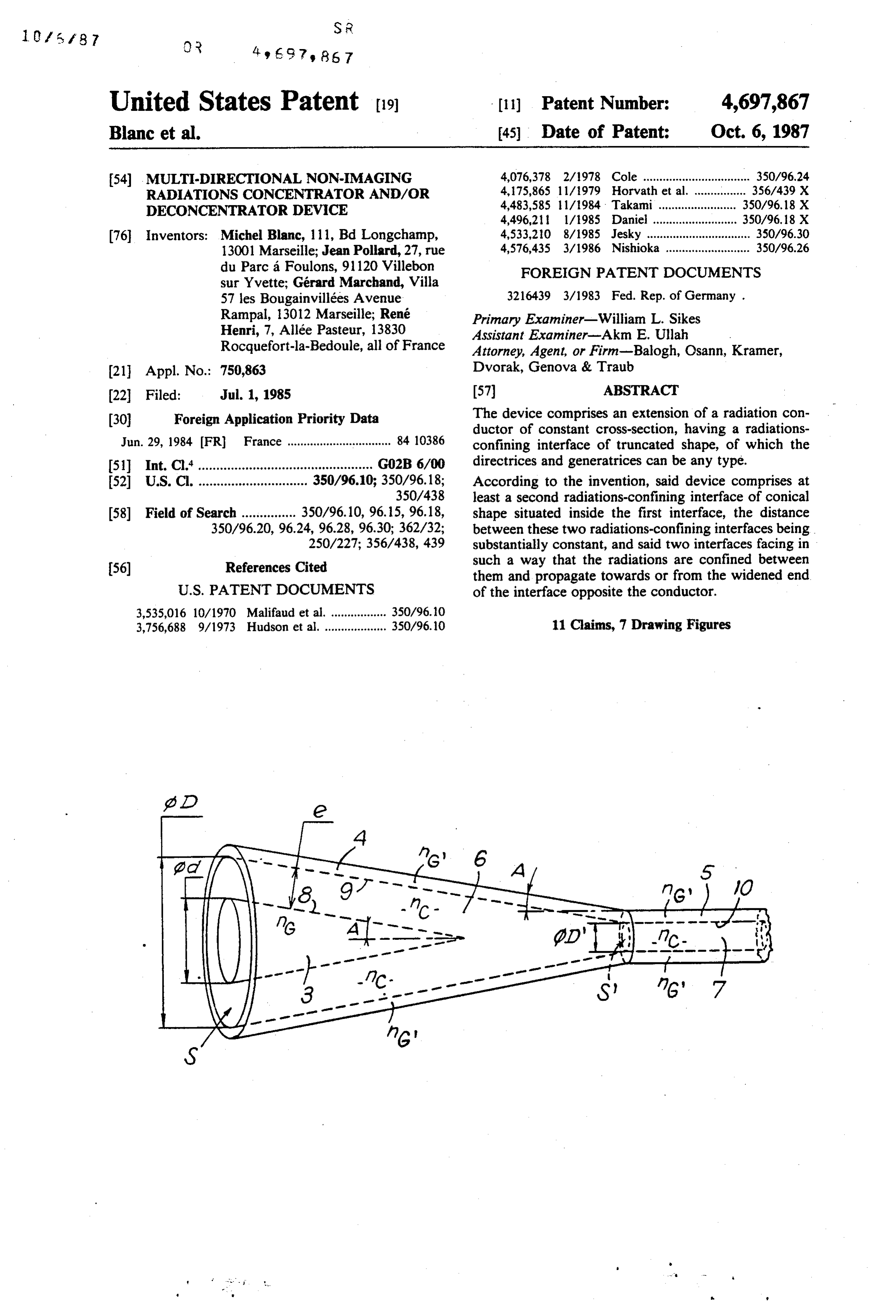
Page 1 — bibliographic record
United States Patent (19) (11) Patent Number: 4,697,867 Blanc et al. 45) Date of Patent: Oct. 6, 1987 54 MULTI-DIRECTIONAL NON-IMAGING 4,076,378 2/1978 Cole ................................. 350/96.24 RADATIONS CONCENTRATOR AND/OR 4, 75,865 1 1/979 Horvath et al. ................ 356/439 X DECONCENTRATOR DEVICE 4,483,585 l/1984 Takami........................ 350/96.18 X 4,496,21 1/1985 Daniel .......................... 350/96.18 X 76 Inventors: Michel Blanc, 111, Bd Longchamp, 4,533,210 8/1985 Jesky ................................ 350/96.30 13001 Marseille; Jean Pollard, 27, rue 4,576,435 3/1986 Nishioka .......................... 350/96.26 du Parc à Foulons, 91 120 Villebon FOREIGN PATENT DOCUMENTS sur Yvette; Gérard Marchand, Villa 57 les Bougainvillées Avenue 3216439 3/1983 Fed. Rep. of Germany .
Rampal, 13012 Marseille; René Primary Examiner-William L. Sikes
Henri, 7, Allée Pasteur, 13830 Assistant Examiner-Akm E. Ullah
Rocquefort-la-Bedoule, all of France Attorney, Agent, or Firm-Balogh, Osann, Kramer, (21) Appl. No.: 750,863 Dvorak, Genova & Traub 22 Filed: Jul. 1, 1985 57 ABSTRACT 30 Foreign Application Priority Data The device comprises an extension of a radiation con ductor of constant cross-section, having a radiations
Jun. 29, 1984 (FR) France ................................ 84 10386 confining interface of truncated shape, of which the 51) Int. Cl."................................................ GO2B 6/00 directrices and generatrices can be any type. 52 U.S. Cl. .............................. 350/96.10; 350/96.18; According to the invention, said device comprises at 350/438 least a second radiations-confining interface of conical 58 Field of Search ............... 350/96.10, 96.15, 96.18, shape situated inside the first interface, the distance 350/96.20, 96.24, 96.28, 96.30; 362/32; between these two radiations-confining interfaces being 250/227; 356/438,439 substantially constant, and said two interfaces facing in 56) References Cited such a way that the radiations are confined between them and propagate towards or from the widened end
3,535,016 10/1970 Malifaud et al. ................. 350/96.10 3,756,688 9/1973 Hudson et al. ................... 350/96.10 11 Claims, 7 Drawing Figures
Page 2
Drawing sheet — no readable text.
Page 3
Drawing sheet — no readable text.
Page 4
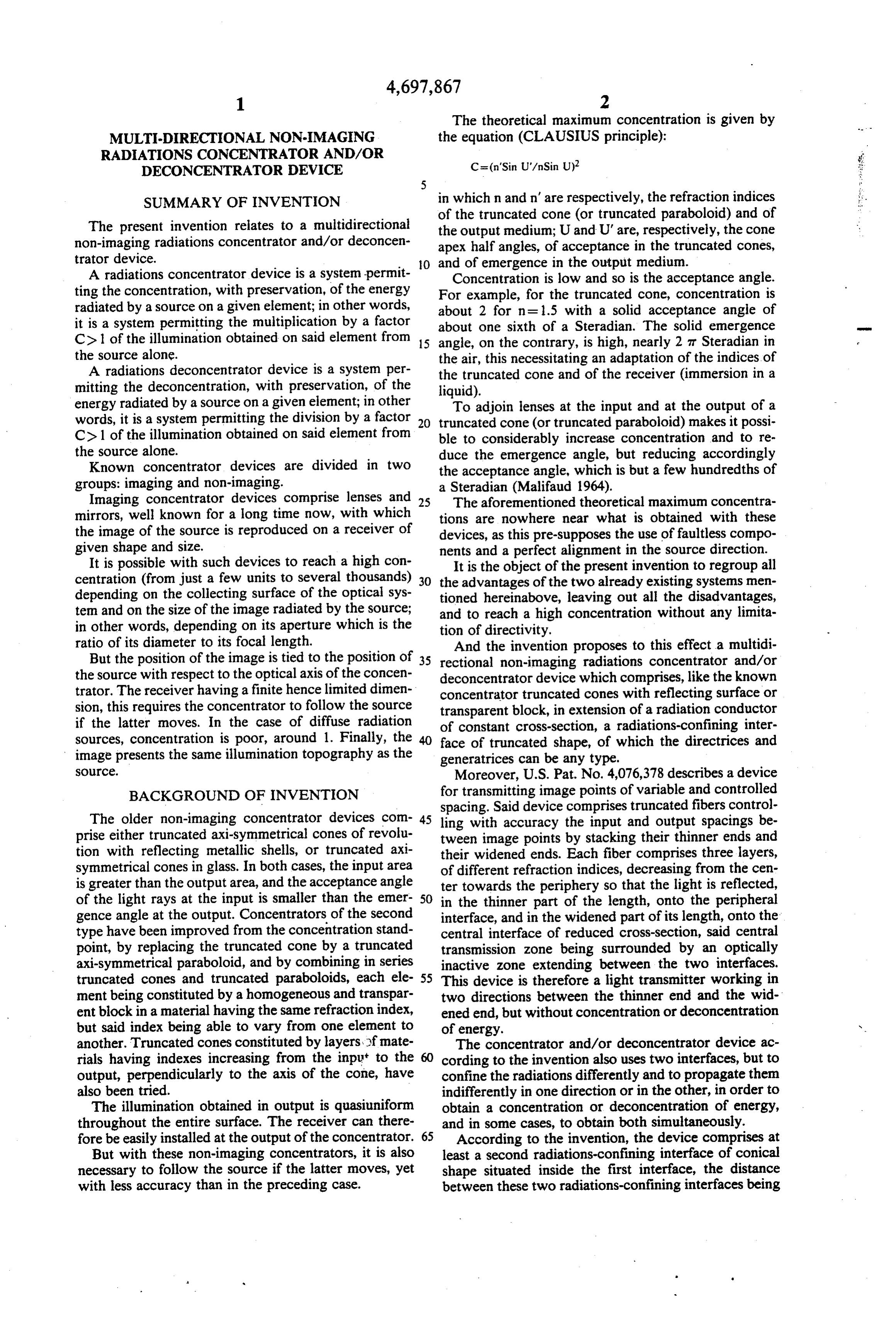
The theoretical maximum concentration is given by
MULTI-DIRECTIONAL NON-MAGNG the equation (CLAUSIUS principle):
RADIATIONS CONCENTRATOR AND/OR
DECONCENTRATOR DEVICE
SUMMARY OF INVENTION in which n and n' are respectively, the refraction indices of the truncated cone (or truncated paraboloid) and of
The present invention relates to a multidirectional the output medium; U and U' are, respectively, the cone non-imaging radiations concentrator and/or deconcen apex half angles, of acceptance in the truncated cones, trator device. O and of emergence in the output medium. A radiations concentrator device is a system permit ting the concentration, with preservation, of the energy ForConcentration is low and so is the acceptance angle. example, for the truncated cone, concentration is radiated by a source on a given element; in other words, about 2 for n=1.5 with a solid acceptance angle of it is a system permitting the multiplication by a factor about one sixth of a Steradian. The solid emergence C> 1 of the illumination obtained on said element from 15 angle, on the contrary, is high, nearly 2 at Steradian in the source alone. the air, this necessitating an adaptation of the indices of A radiations deconcentrator device is a system per the truncated cone and of the receiver (immersion in a mitting the deconcentration, with preservation, of the liquid).
energy radiated by a source on a given element; in other To adjoin lenses at the input and at the output of a words, it is a system permitting the division by a factor 20 truncated cone (or truncated paraboloid) makes it possi C> 1 of the illumination obtained on said element from ble to considerably increase concentration and to re the source alone. duce the emergence angle, but reducing accordingly Known concentrator devices are divided in two the acceptance angle, which is but a few hundredths of groups: imaging and non-imaging. a Steradian (Malifaud 1964).
Imaging concentrator devices comprise lenses and is The aforementioned theoretical maximum concentra mirrors, well known for a long time now, with which tions are nowhere near what is obtained with these the image of the source is reproduced on a receiver of devices, as this pre-supposes the use of faultless compo given shape and size. nents and a perfect alignment in the source direction. It is possible with such devices to reach a high con It is the object of the present invention to regroup all centration (from just a few units to several thousands) so the advantages of the two already existing systems men depending on the collecting surface of the optical sys tioned hereinabove, leaving out all the disadvantages, ten and on the size of the image radiated by the source; and to reach a high concentration without any limita in other words, depending on its aperture which is the tion of directivity.
ratio of its diameter to its focal length. And the invention proposes to this effect a multidi But the position of the image is tied to the position of 35 rectional non-imaging radiations concentrator and/or the source with respect to the optical axis of the concen deconcentrator device which comprises, like the known trator. The receiver having a finite hence limited dimen concentrator truncated cones with reflecting surface or sion, this requires the concentrator to follow the source transparent block, in extension of a radiation conductor if the latter moves. In the case of diffuse radiation of constant cross-section, a radiations-confining inter sources, concentration is poor, around 1. Finally, the 40 face of truncated shape, of which the directrices and image presents the same illumination topography as the generatrices can be any type.
SOC. Moreover, U.S. Pat. No. 4,076,378 describes a device BACKGROUND OF INVENTION for transmitting image points of variable and controlled spacing. Said device comprises truncated fibers control
The older non-imaging concentrator devices com- 45 ling with accuracy the input and output spacings be prise either truncated axi-symmetrical cones of revolu tween image points by stacking their thinner ends and tion with reflecting metallic shells, or truncated axi their widened ends. Each fiber comprises three layers, symmetrical cones in glass. In both cases, the input area of different refraction indices, decreasing from the cen is greater than the output area, and the acceptance angle ter towards the periphery so that the light is reflected, of the light rays at the input is smaller than the emer- 50 in the thinner part of the length, onto the peripheral gence angle at the output. Concentrators of the second interface, and in the widened part of its length, onto the type have been improved from the concentration stand central interface of reduced cross-section, said central point, by replacing the truncated cone by a truncated transmission zone being surrounded by an optically axi-symmetrical paraboloid, and by combining in series inactive zone extending between the two interfaces. truncated cones and truncated paraboloids, each ele- 55 This device is therefore a light transmitter working in ment being constituted by a homogeneous and transpar two directions between the thinner end and the wid ent block in a material having the same refraction index, ened end, but without concentration or deconcentration but said index being able to vary from one element to of energy.
another. Truncated cones constituted by layers, f mate The concentrator and/or deconcentrator device ac rials having indexes increasing from the input to the 60 cording to the invention also uses two interfaces, but to output, perpendicularly to the axis of the cone, have confine the radiations differently and to propagate them also been tried. indifferently in one direction or in the other, in order to The illumination obtained in output is quasiuniform obtain a concentration or deconcentration of energy, throughout the entire surface. The receiver can there and in some cases, to obtain both simultaneously. fore be easily installed at the output of the concentrator. 65 According to the invention, the device comprises at But with these non-imaging concentrators, it is also least a second radiations-confining interface of conical necessary to follow the source if the latter moves, yet shape situated inside the first interface, the distance with less accuracy than in the preceding case. between these two radiations-confining interfaces being
Page 5
substantially constant, and said two interfaces facing in tion being to use materials compatible with the selected such a way that the radiations are confined between spectral range of the radiations involved. them and propagate towards or from the widened end According to the embodiment illustrated in FIG. 2, of the interface opposite the conductor. the concentrator device essentially consists in a trun With such an improved device, it is possible to obtain cated axi-symmetrical system in transparent materials a high acceptance angle, capable of reaching as much as for the selected spectral range.
the whole of the frontal half-space. This property makes Said device comprises:
it possible to concentrate the punctual sources (specific an inner core 3 of external diameter d, of half angle A light source) as well as the diffuse sources (general at the apex and of refraction index nG, ending into a ambient background light) and to use the concentrator 10 point, in a readily choosable fixed position. a truncated peripheral cladding 4 of inner input diam In addition, the illumination is uniform in output eter D, of inner output diameter D' (D' being smaller whatever the source or sources. than D), of half angle A at the apex (the same half angle Also the concentration is high, theoretically unlim 5 as that of the inner core, so that the generatrices of the ited for a given configuration since it is only dependent inner surface of the cladding are parallel to those of the on the ratio of the input and output surfaces, or by external surface of the core as long as said core is fitted placing several systems in series. co-axially inside the cladding), of refraction index no, Such elementary structures with two confining inter ending into a cylindrical tubular cladding 5 of same faces may be coupled: index.
in parallel, the first interface of a structure being 20 a truncated tubular funnel 6 filling the space between contiguous to the second interface of the structure sur the cladding 4 and the core 3, said funnel having a uni rounding it, and all first interfaces being connected with form thickness e and a refraction index inc, said funnel the same radiation conductor, or in series, the conductor of one being connected 25 7being further extended by an optical conductor or fiber of same refraction index which extends into said clad with the widened end of the other, ding 5.
or else, both in series and in parallel. Understandably, for radiations to propagate by total
BRIEF DESCRIPTION OF THE DRAWINGS
reflection onto interfaces 8 and 9 which are constituted
The invention will be more readily understood on reading the following description with reference to the 30 by face the external surface of the core 3 and the inner sur of the cladding 4, it is necessary that:
accompanying drawings in which:
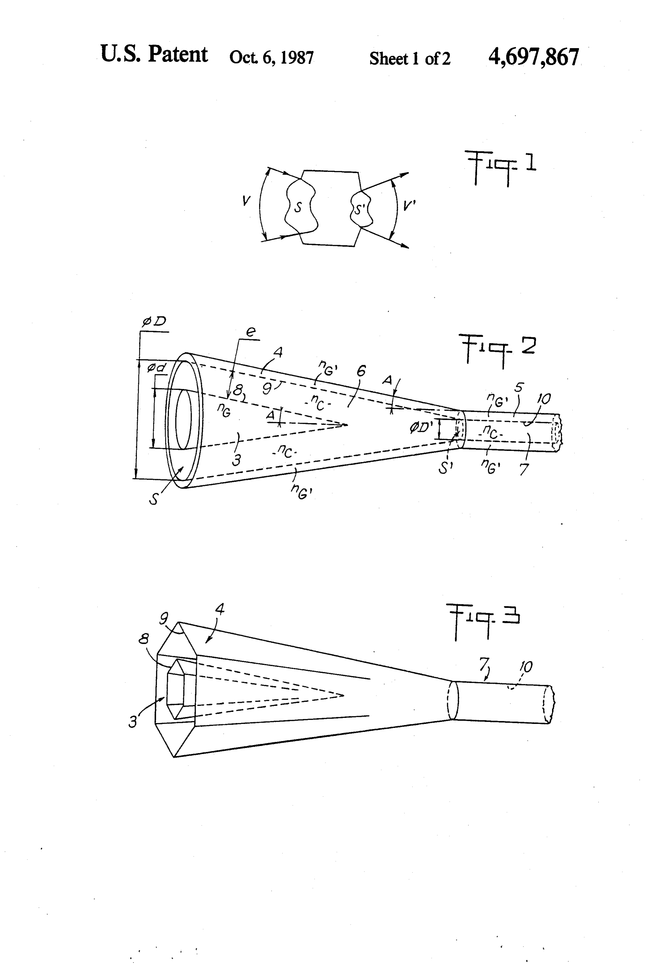
FIG. 1 is a detailed diagram of the principle of the nexternal medium sing<"c invention,
FIG. 2 is a perspective view illustrating a first em and bodiment of the device according to the invention, 35 where transparent materials of different refraction indi nexternal medium Sno <nc ces are used,
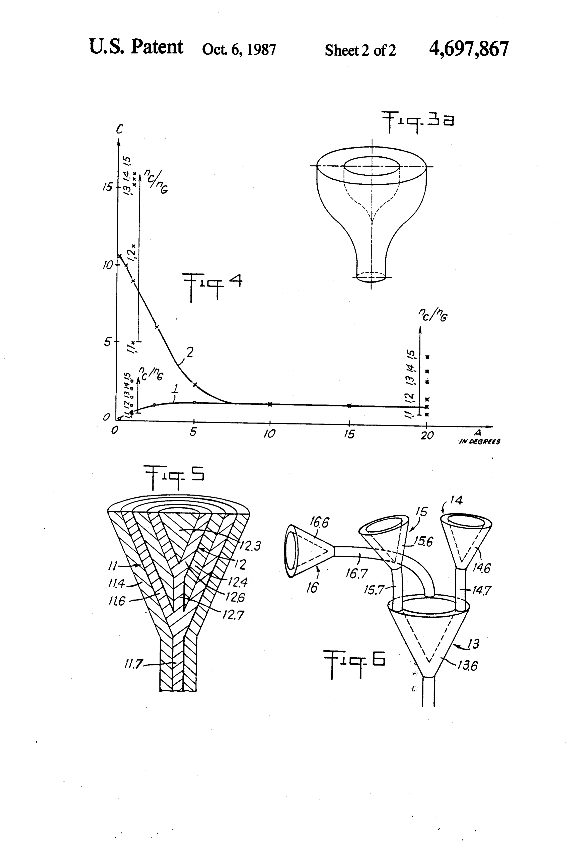
FIGS. 3 and 3A are perspective views illustrating a Said external medium being generally air, its index is second embodiment of the invention and a variant of the equal to 1, and the core being generally constituted by device equipped with reflecting surfaces. the same material as the cladding, ng then is equal to FIG. 4 is a graph showing the variation of the con G.
centration C as a function of the half-angle A at the apex In the above-defined case, total reflection is abrupt of the truncated cone, by way of two curves 1 and 2 on and takes place by "step index' from no to no and from which the significant points are marked by small circles nC to nG'.
for a conventional truncated cone and respectively by 45 But the invention is also applicable to the case where small crosses for a device according to the invention, total reflection proceeds by successive bendings and FIG. 5 is a diagram in half perspective, half cross-sec takes place then by "gradient index', acting on the tion of a parallel coupling of two elementary structures: material situated on the boundary between the inter cladding and inner core.
FIG. 6 is a view similar to FIG. 5 concerning a cou 50 faces rather so that its refraction index varies not abruptly, but following a certain progression.
pling in series of a collecting elementary structure with Said total reflection applies not only to interfaces 8 derived elementary structures. and 9 of the device, but also to interface 10 of the radia DETAILED DESCRIPTION OF PREFERRED tions conductor which, according to the first example EMBODIMENT of embodiment, is constituted by optical fiber 7 cladded 55 by cladding 5.
The concentrator device described hereinafter is a
According to the second example of embodiment passive optical element permitting to collect through a illustrated surface S the radiating energy from inside a solid angle in FIG. 3, the concentrator device essentially consists in
V and to redistribute all or part of it through a surface part is hexagonal,a truncated system, of which the widened S', inside a solid angle V' (FIG. 1). If Esand Es, are the tions conductor isthecircularsmall end connected to the radia and the generatraces are respective illuminations of surfaces S and S', the con centration C is defined as being the ratio of Es, to Es. substantially straight, said system being formed of per The system is a concentrator if C is greater than 1. The fectly reflecting materials within the selected spectral system being passive, this obviously presupposes that range, the surface S is smaller than the surface S. 65 The resulting reflection is of the metallic type or of Such a system can be used with X-rays in the same the interferential selective type through a judicious way as it can be used with microwaves (radar), even selection of thin layers deposited on the interface or with U.V.s, visible, infrared radiations, the only condi interfaces.
Page 6
In this second embodiment there can be found, the invention to reach a concentration C= 16 for a ratio interface 8 of the core 3, the interface 9 of the cladding nc/ng= 1.3 this giving a half angle at the apex of the 4 and the interface 10 of the con-ductor or fiber 7. acceptance cone of 56.
Whatever the embodiment selected, any one at least The concentration value may be optimized for every of interfaces 8, 9 and 10 may be, for part of it only couple of indices by altering the values of ratios d/D (length and/or periphery) of a certain type (refraction, and S/S".
metallic reflection, interferential selective reflection. . . With infrared, a device having a funnel in germanium ) and for another part, of another type. (nc=4) immersed in air (nG= 1) gives, for an angle And also whatever the embodiment selected, the As 230' and a ratio d/D=5.8, a concentration of device, as elementary structure, comprises a cladding 4 O around 5.
of which the interface 9 is a conical surface with any It is obvious that the concentrator device as an ele type of directrices and generatrices, this property being mentary structure, is that illustrated in FIG. 2 or in also found in interface 8 of the core 3 which is substan FIG. 3. But this device may be more complex and be tially equidistant from said interface 9. constituted by a plurality of elementary structures. For example, the directrix may be circular (FIG. 2) 15 According to the embodiment diagrammatically ill oval, elliptic, square, rectangular, hexagonal (FIG. 3) or lustrated in FIG. 5, two elementary structures 11 and 12 other; the generatrices may be straight (FIGS. 2 and 3), are mounted in parallel. In this case, the funnel 11.6 of jagged, incurved. (FIG. 3A); the directrix may evolve the structure 11 which is extended by the optical fiber in shape along the axis (FIG. 3) and the generatrices 11.7 is interposed between the cladding 11.4 of said may adapt to this evolution by their shape and orienta 20 structure and its core forming the cladding 12.4 of the tion. co-axial structure 12; the filling 12.6 of said structure 12 This reflecting truncated concentrator device (FIGS. integral with an extension 12.7 of the fiber 11.7 is inter 1 and 2) combines the property of a truncated cone posed between said cladding core 12.4 and the core 12.3 which is to pass from one to the other of its bordering of said structure 12.
surfaces, external and internal, with the property of the 25 In other words, the first confining interface 9 of the optical fiber which is to convey the rays without losses, structure 12 is contiguous to the second confining inter through the medium of index nc, by successive reflec face 8 of the structure around it, all first interfaces being tions on the interfaces 8 and 9, respectively of the medi joined to the interface 10 of the radiations conductor 7. ums of index nc and nG, inc and no. It is understood that a plurality of elementary struc It is comparable to an original termination of an opti 30 tures may be mounted in parallel by co-axial interlock cal fiber, permitting the concentration of the energy ing, all of which structures defining a co-axial common inside the fiber or on the contrary, the deconcentration optical fiber.
of said energy from said fiber. According to the embodiment diagrammatically il Curves 1 and 2 of the graph shown in FIG. 4 illustrate lustrated in FIG. 6, the device comprises an elementary the variation of the concentration C as a function of the 35 collector structure 13, on the funnel 13.6 of which are half angle A at the apex of a conventional truncated mounted, in series, optical fibers 14.7, 15.7, 16.7. . . cone (curve 1 at the significant points marked with a funnels 14.6, 15.6, 16.6. . . , a plurality of deriyed ele small circle) and of a device according to the invention mentary structures 14, 15, 16..., each one of which can (curve 2 with significant points marked with a small cooperate with other derived structures. cross). For these two curves 1 and 2, d = D/2 and The device according to the invention, whether ele D/D'=5. The half angle A varies between 0 and 20. mentary or complex, is comparable to an original termi The refraction indices are inc= 1.6 and no=ng", = 1.4, nation of an optical fiber, permitting the concentration i.e. a rationC/ngs 1.143, this giving a half angle at the of the energy inside the fiber, or on the contrary, the apex of the acceptance cone of 51 degrees. deconcentration thereof, depending on whether the In the example illustrated by curves 1 and 2, it is 45 radiation flux penetrates through the widened end of found that for A greater than 7, the conventional trun the device or through the conductor respectively; it is cated cone and the device according to the invention possible in some cases, to simultaneously combine the give the same concentration D, around 1.2. two functions for example for lighting a surface and at But for angles A smaller than 7, the device accord the same time, for collecting the energy reflected by ing to the invention is found to be much better as it 50 said surface. Therefore, said device must be considered makes it possible to reach a concentration C= 10 for an as radiat-ions- concentrator and/or deconcentrator. angle A=30'( degree), whereas with the conventional The device according to the invention is applicable to truncated cone, it is only possible, with the same angle, a great number of industrial fields, such as the follow to reach 0.3. ing:
Such concentrations are obtained for a uniform dif 55 visualization: transmission, enlargement or reduction fuse source covering the whole acceptance angle of the of natural or synthetic images, flat display panels, . device.
This phenomenon is generalized and to check this, lighting: pick-up, collection, transmission, deflection, one should examine the resulting network of the curves, zoncentration, mixing of light energy at different when the index ratio is caused to vary. For clarity's wavelengths for illumination of surfaces or vol sake, this network is not shown in FIG. 4. But the signif umes from punctual or diffuse sources. . . icant points have been marked on the graph for values energetics: pick-up, collection, concentration, trans of A equal to 1" and 20, the rationC/ng being indicated mission of radiating energy, even if diffused, for for each of these points by portions of y-axes. local use or transformation. . . For example solar It is found that the device according to the invention 65 heating (even by shaded sun) use of silicon solar and the conventional truncated cone are substantially cells under high concentration, . . . equivalent for values of Agreater than 5. For example, instrumentation: collection of very low level energy, at 230, it is possible with the device according to the spectroscopy, astronomy, . . .
Page 7
opto-electronics: interface-components for data 5. A device as claimed in claim 3, wherein at least one transmission optical fibers (connections, light sig of said first or second interfaces is of the "step index" nal injection, coupling, ...). type.
microwaves: micro-wave concentrators, . . . 6. A device as claimed in claim 3, wherein at least one What we claim is: 5 of said first or second interfaces is of the "gradient 1. A multidirectional non-imaging device for optimiz index” type.
ing concentration and/or deconcentration of radiations 7. A device as claimed in claim 1, wherein said second and for use as an extension of a radiation conductor of interface is disposed within said first interface and is constant cross-section, comprising: spaced apart from said radiation conductor. a first means for forming a first radiation confining 10 8. A device as claimed in claim 1, wherein at least one tapered surface having a truncated shape and being of said interfaces is, over at least a part of its surface, of disposed with its narrow end adjacent an end of the total refraction index type, and a material disposed said radiation conductor and having directrices of between said first and said second interfaces and having any closed type and having generatrices of any a refraction index that is higher than the refraction form consistent with said tapered surface; 15 indices of the materials disposed outside of said first and a second means forming at least one second radiation said second interfaces.
confining tapered surface inscribed within said first 9. An arrangement comprising a plurality of devices surface means; and as defined in claim 1, wherein each individual device is a radiation transparent medium between said first and interconnected in parallel, said first interface of one second surface means, with the spacing between 20 device being contiguous to the said second interface of said first and second surface means being substan another device surrounding said one device, with inter tially constant to enable radiations confined there faces of all devices having a common connection to the between to propagate toward and/or away from same radiation conductor.
the widened end of the device. 10. An arrangement comprising a plurality of devices 2. A device as claimed in claim 1, wherein the surface 25 as claimed in claim 1, wherein each individual device is of at least one of said first or second interfaces is at least interconnected with another individual device in series, partly of the metallic reflection type. the radiation conductor of one device being connected 3. A device as claimed in claim 1, wherein the surface to the widened end of an adjacent device. of at least one of said first or second interfaces is at least 11. An arrangement as claimed in claim 10, wherein partly of the total reflection by refraction type. 3O the two interfaces of each device are connected in par 4. A device as claimed in claim 1, wherein the surface allel on the widened end of one common device with of at least one of said first or second interfaces is at least two interfaces.
partly of the interferential selective reflection type.
Provenance
- Collection
- Cited prior art
- Original PDF
- patentimages.storage.googleapis.com →
- Filed
- 1985-07-01
- Pages
- 7
- Method
- pdftotext (the PDF's own text layer) + pdftoppm 300dpi page scans
- Source
- Google Patents bibliographic record
- Granted
- 1987-10-06
- Inventors
- Michel Blanc; Jean Pollard; Gerard Marchand; Rene Henri
- Transcribed from
- patentimages.storage.googleapis.com →