patent · US4483007
Energy transmission with respect to convex sources and receivers
13 November 1984
Page 1 — bibliographic record
United States Patent (19) 11 Patent Number: 4,483,007 Winston 45) Date of Patent: Nov. 13, 1984 54 ENERGY TRANSMISSION WITH RESPECT 56) References Cited
TO CONVEX SOURCES AND RECEIVERS
75 Inventor: Roland Winston, Chicago, Ill. 3,064,781. 1/1965 Goldberg . . . . . . . . . . . . . . . . . . . . . . . . . . . . . 372/38 3,238,470 3/1966 Mooney ... ... 372/72 3,634,777 1/1972 Uchida ...... ... 372/72 (73) Assignee: The University of Chicago, Chicago,
Ill.
3,893,754 7/1975 McInally. . . . . . . . . . . . . . 350/294
Primary Examiner-William L. Sikes
Assistant Examiner-Léon Scott, Jr.
21) Appl. No.: 282,232 Attorney, Agent, or Firm-Marshall, O'Toole, Gerstein, Murray & Bicknell .
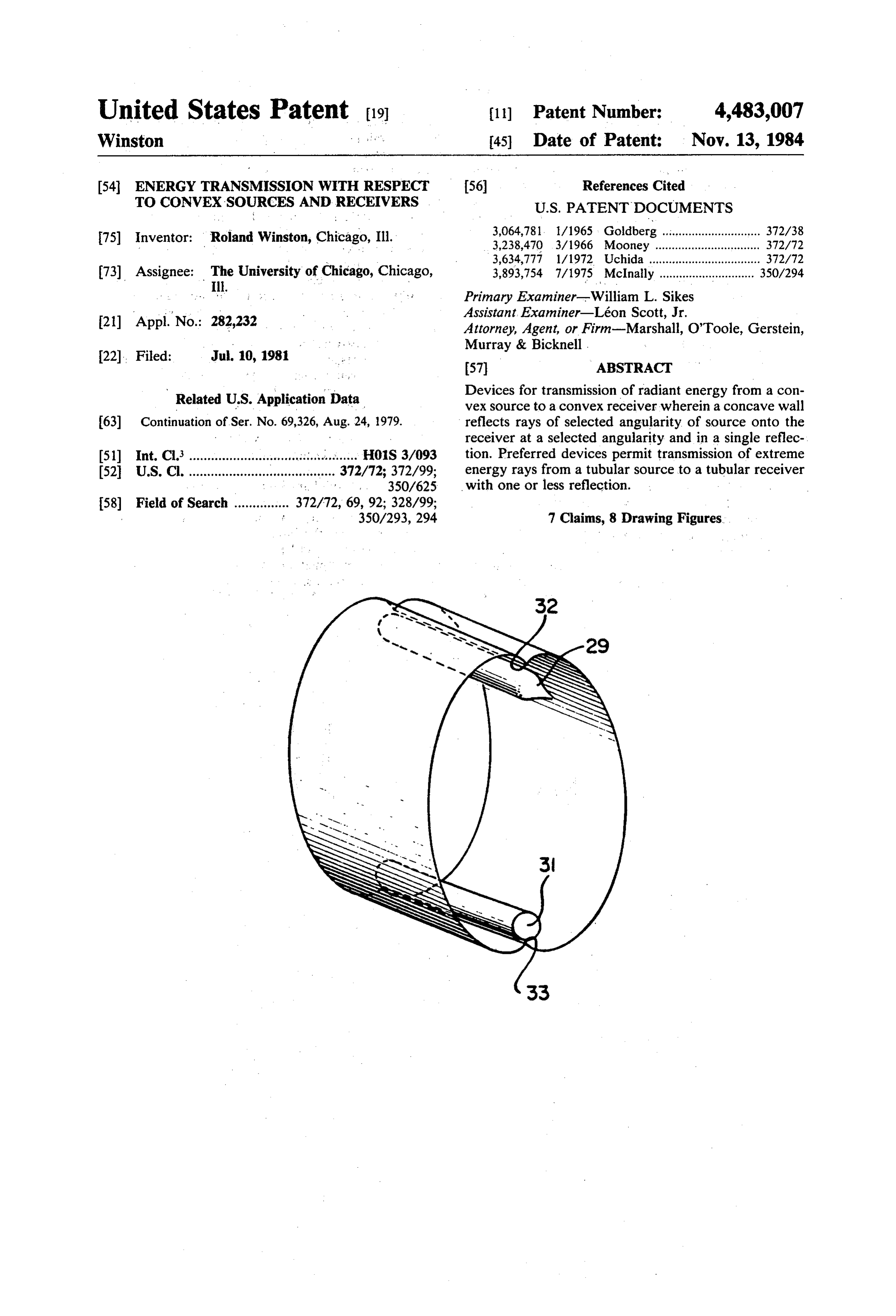
Filed: Jul. 10, 1981 57) ABSTRACT Related U.S. Application Data Devices for transmission of radiant energy from a con vex source to a convex receiver wherein a concave wall (63) Continuation of Ser. No. 69,326, Aug. 24, 1979. reflects rays of selected angularity of source onto the receiver at a selected angularity and in a single reflec (51) Int, C. .............................................. H01S 3/093 tion. Preferred devices permit transmission of extreme 52 U.S. C. ...................... r a 8 8 372/72; 372/99; energy rays from a tubular source to a tubular receiver
; : ; 350/293,294 7 Claims, 8 Drawing Figures
Page 2
Drawing sheet — no readable text.
Page 3
Drawing sheet — no readable text.
Page 4
positioned with respect to receiver and source as to
ENERGY TRANSMISSION WITH RESPECT TO reflect source rays emanating from a first predeter CONVEX SOURCES AND RECEIVERS mined angle onto the receiver, at a second predeter mined angle and in a single reflection. As such, the
This is a continuation of application Ser. No. 69,326, 5 devices of the present invention-viewed in the context filed Aug. 24, 1979. of concentrators-are capable of attaining the maxi BACKGROUND mum permissible concentration allowed by the Second Law of Thermodynamics.
The present invention relates generally to radiant It is presently contemplated that the most signifi energy transmission and more particularly to improved 10. cantly useful application for devices of this type is in the devices for the efficient transmission of energy emanat field of laser energy generation. In a most preferred ing from a geometrically convex source to a geometri embodiment of the invention, rays emanating tangen cally convex receiver. tially from a tubular source (such as a flash tube) im Applicant's publication appearing in Solar Energy pinge upon the prescribed wall and are reflected tan Vol. 16, No. 2, pages 89-95 (1974), as well as his U.S. 15 gentially onto a tubular receiver (such as a lasing rod) Pat. Nos. 3,957,031, 4,002,499, 4,114,592 and 4,130,107 having its axis in parallel alignment with the source. describe techniques for generating the ideal reflective Remarkably, the precise convex curving slope of the wall contour for certain energy transmission (i.e., col wall in such an embodiment may be defined in terms of lection and emission) devices. Applicant's U.S. Pat. No. an elegantly simple "string construction.” 4,240,692, issued Dec. 23, 1980, is addressed to shaping Devices of the invention may be provided with a of such ideally reflecting walls in a manner consistent reflective wall partially or wholly "enclosing” the with assuring total internal reflectivity for the devices. space surrounding the source and receiver and may also Such concentrator devices are generally characterized include refractive lens elements. Further, the reflective by a suitable reflective wall contour (parabolic, ellipti wall portion may be provided in the form of a specular cal, etc.) permitting extreme incident rays from an en 25 surface or as the optical boundary between media of ergy source to be transformed, after at most one reflec differing refractive indices (with reflection resulting tion, into the extreme rays incident on an energy absorb from total internal reflectivity). ing body. In each case the reflective wall contour is Other aspects and advantages of the present inven shaped to assume the maximum possible slope consis tion will become apparent upon consideration of the tent with reflecting the extreme rays onto the absorber, 30 following detailed description and the drawing subject to accommodation for such subsidiary condi wherein:
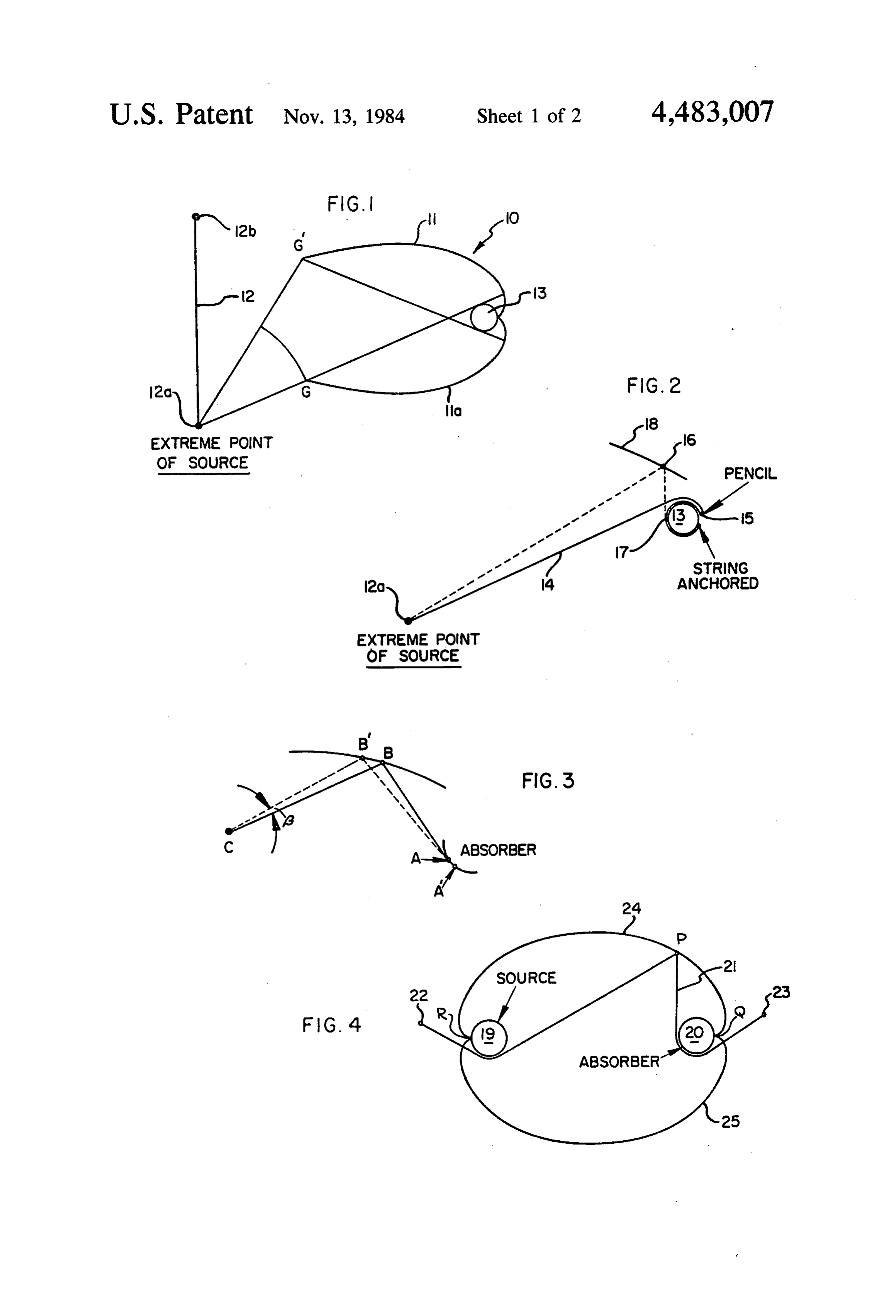
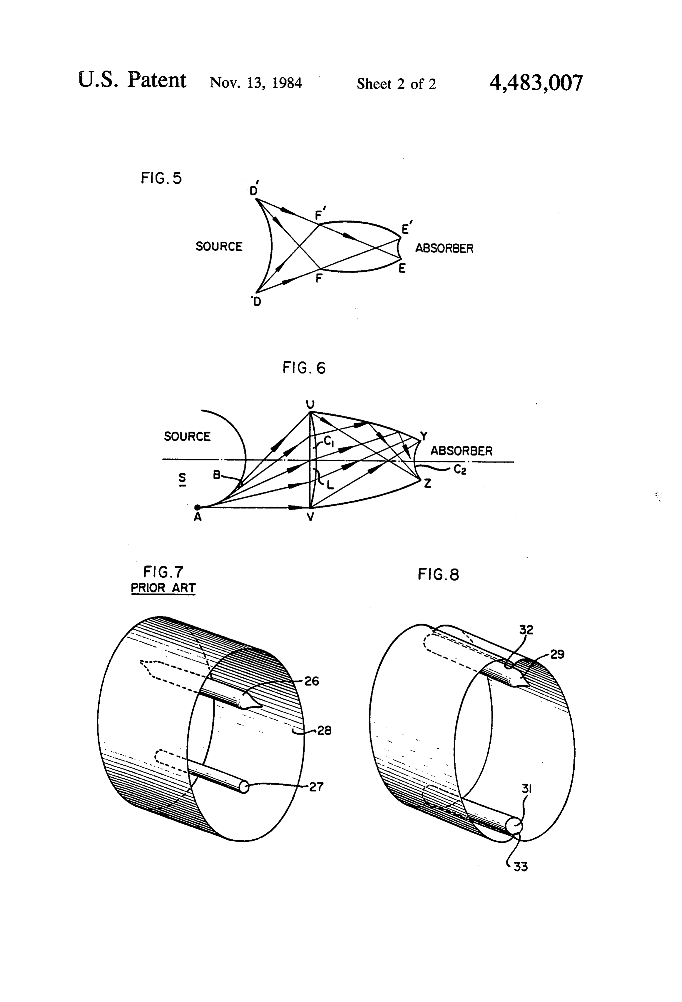
tions as specification of a selected maximum angle of FIGS. 1 to 3 illustrates the context for determining incidence along the absorber or a requirement that re the positioning and shaping of a reflective wall of a flection along a portion of the wall be accomplished by device of the invention according to the string con total internal reflectivity. In all such cases, however, the 35 struction;
extreme incidence rays treated were those emanating FIGS. 4 and 5 illustrate the string construction ap either from a "point” source located at infinity or a plied to a convex source and receiver according to the source which is flat and located at a finite distance from invention;
the concentrator. FIG. 6 illustrates a device of the invention including There exists a long standing need in the art of energy a lens element;
transmission for devices capable of high efficiency in FIG. 7 schematically illustrates a prior art laser gen transmitting radiant energy from a convex source to a erating device; and, convex receiver located at a finite distance from the FIG. 8 schematically illustrates a laser generating source. Examples of such devices include lamps in device according to the invention.
tended to uniformly illuminate a convex surface with 45 DETALED DESCRIPTION direct and reflected energy from, e.g., a fluorescent light tube. The need to assure efficient, uniform energy As employed herein, "convex' and 'geometrically transmission is particularly acute in the design of cavity convex' shall be synonymous and designate any non pump systems for the transformation of the power spec planar, non-concave shape for operatively opposed trum of a flash tube to that within the space occupied by SO surfaces of energy sources and receivers. Cross-sec a rod of lasing material. A wide variety of designs for tional shapes thus comprehended by the terms include mirror cavity systems have been proposed in the laser circles, ellipses and the like and segments of such shapes art (see, e.g., Mahlein, et al., Laser Devices and Tech (e.g., arcs of circles and parabolas) as well as irregular niques pp. 508-517 in "Laser Handbook'', Vol 1, North shapes which are predominantly convex. By way of Holland Publishing, Amsterdam, Holland (1972) but 55 illustration, the present invention provides for efficient none have consistently achieved the desired optimal transmission from a tubular energy source (which re levels of energy transfer efficiency. veals a circular cross-section) to a tubular receiver or BRIEF SUMMARY trap having the same or different cross-sectional diame ter. The devices are equally efficient in transmitting
The present invention provides novel devices for the from a source surface revealed in cross section as an arc transmission of radiant energy from a geometrically of a circle to a receiver tube, or from tube to arc. convex source to a geometrically convex receiver. Sources and receivers having "ribbed' surfaces but More specifically, the devices of the invention provide essentially convex cross-sections, and sources and re an improvement in prior art systems wherein a wall ceivers provided in fin-like configurations, are also surface adjacent the receiver and/or source is employed 65 comprehended. Certain exemplary receiver and source to reflect energy emanating from the source onto the shapes encompassed by the term "convex' are shown in receiver. The reflecting wall portion of devices of the the above-noted U.S. Pat. No. 4,002,499. The terms, invention is concave, non-elliptical, and so shaped and "absorber", "receiver' and "trap' shall be employed
Page 5
synonymously to designate any suitable object: or de vice which may be employed to receive radiant energy Thus, by Fermat's principle, segment BB' must be a for director indirect use. The term "surface' may refer portion of the reflecting surface that reflects a ray along to a physical surface or a conceptual surface represent CB into BA.
ing a virtual source or receiver of energy, said virtual 5 FIG. 4 illustrates significant two dimensional aspects surface being chosen: to accommodate tolerance re aofdevicethe above string construction method generalized to according to the invention. For ease of illustra quirements, gaps between source or receiver and re flecting wall, and the like. . .. . . . tion, both source 19 and receiver 20 are shown as circu ; : As employed herein a "string construction curve' lar in cross-section and having equal diameters. The shall mean and include that smooth, operatively convex 10 string 21 is anchored to two points, 22 and 23, located curve generated with respect to convex source and anywhere operatively rearward respectively of source receiver surfaces according to the method hereafter point 19 and absorber 20, and stretched with the pencil to described with respect to FIGS. 1 through 3 and 4. P. The length of string 21 is selected so that the Devices of the present invention operate to transmit 15 pencil point may be moved to reach point Q when radiant energy emanating from a convex source at a first wound around the receiver. Sliding movement of the pencil within the limits imposed by the string so posi predetermined angle onto a convex receiver, at a sec tioned generates the smooth curving line 24, originating ond predetermined angle and in one or less reflections.
The prescription for shaping and positioning of a reflec atDuring Q, passing through P and extending to the point R. this process the string would "unwind' from tive wall surface relative to the convex source and re 20 around receiver 20 and 'wind' around source 19. The ceiver to accomplish this result will be best understood through preliminary consideration of a shaping and mirror image smooth: curve. 25 in this construction is positioning exercise under hypothetical conditions not generatedto the by applying the string construction method opposing "side' of the source 19 and receiver 20, comprehended by the present invention, i.e., conditions with the string again originating at points 22 and 23 and involving transmission from a planar source located at a 25 having a length sufficient to reach "around in the op finite distance from a convex receiver. ; :. . ..
; FIG. 1 illustrates the two-dimensional solution for posite direction to points Q and R. Geometric analysis of this two
dimensional construc design of a concentrator 10 including reflecting wall tion reveals that the curves 24 and 25 invariably satisfy portions 11 and 11a for reflecting energy rays emanat the condition that any ray emanating tangent to source ing from the planar energy source 12 onto convex re 30 19 will be directed tangent to the receiver 20 after at ceiver 13. The string construction fixing the location most one reflection. All rays emanating from the and concave curvature of wall 11 is as follows (refer source, therefore, will invariably reach the absorber
A string 14 is tied between one extreme point 12a of after none, one, or more reflections. . . ... ." source 12 and a point 15 at the operative rear portion of 35 of Practical considerations imposed by the projected use absorber 13 and the string is pulled taut with the writing thedevices of the invention may dictate a departure from point of a pencil 16, as in the so-called gardener's present in thetoabove-noted "tangent source/tangent to receiver' condition method of drawing an ellipse. The length of the string is string construction curve. Itexample of generation of the may be desired, for exam such that it will be taut when it is pulled right around the convex curving surface 17 of absorber 13 to reach 40 ple, than that reflected rays impinge upon the absorber at less tangency. In such a case, the string construction point 15 as illustrated in FIG. 2. The string 14 then method would still apply to determination of wall shape unwound (as shown by the dashed line), keeping the and location, but the string would be made to "unwind' string taut. The mark of the sliding pencil point (line 18) from the receiver at some predetermined angle of less in this two dimensional construction, together with the than 90°. The geometric companion curve 11a based on rays from the opposing 45 ification, are described conditions more, fully governing this mod in U.S. Pat. No.
extreme point 12b of source 12, describes the correct profile curve allowing for all rays within points G, G' to 4,130,107. A similar minor adjustment would allow for be reflected by reflecting wall portions 11 and 11a onto single emanating reflection (tangent, to the receiver) of all rays from a convex source at a predetermined receiver 13.
To verify that this curve is correct, it need only be 50 to applicationthanof90'.
angle of less Put another way, it is not essential shown that the line segment 18 so drawn is invariably at locating and shaping a string the construction method for the correct angle to produce the desired reflection of a angularity of source or angularity wall reflective
that the selected absorbance be 90.
ray from point source 12a along a line tangent to the It is also worthy of note: that practical considerations surface of receiver 13. This demonstration is provided may dictate some reasonable departure from the de by the illustration of FIG. 3 wherein, for convenience 55 mand of geometric analysis, the extreme point of the source ing wallofbe the string construction method that the reflect has been assigned the letter C, a typical position of the at points Q inandcontact R in with the source and receiver (e.g.,
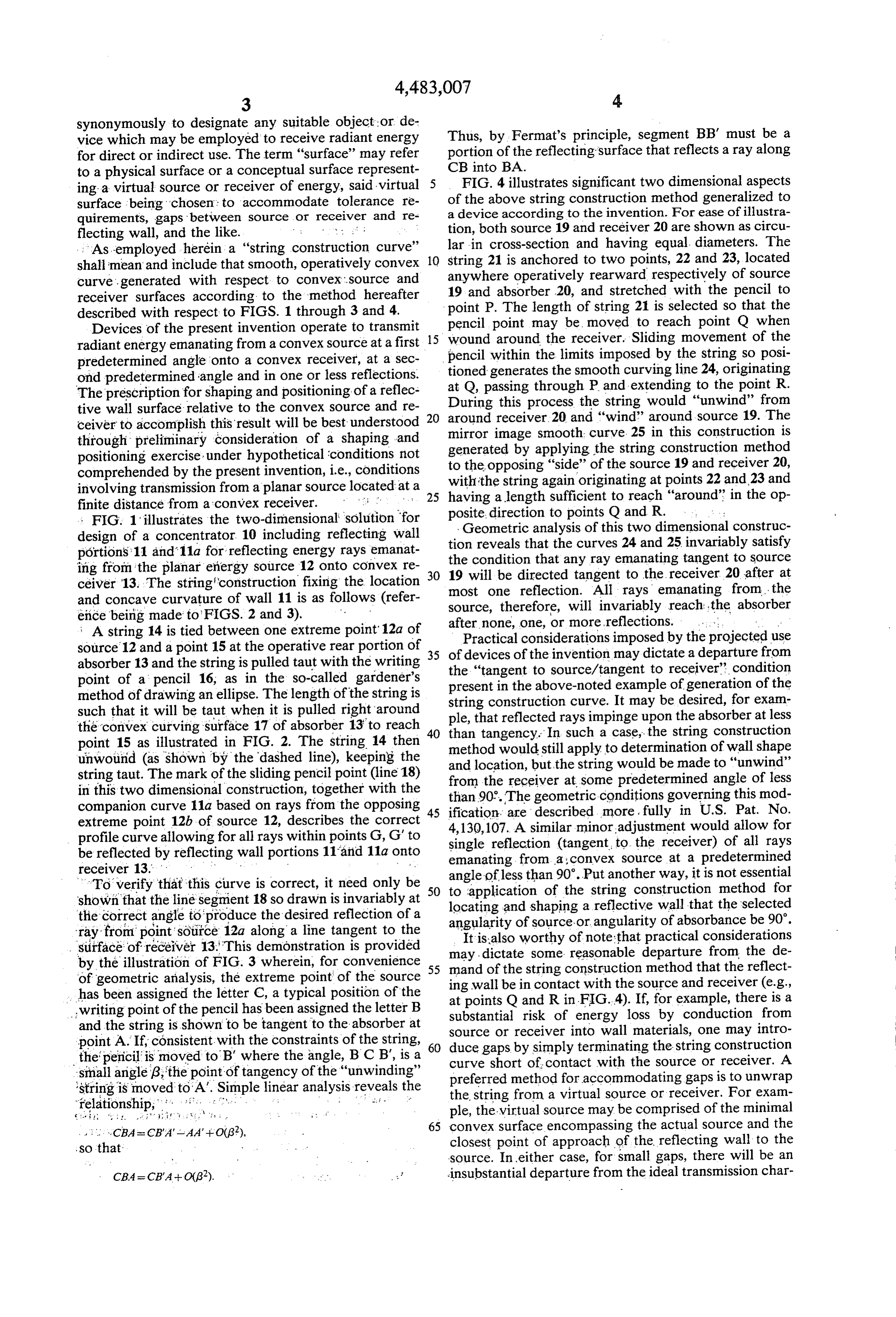
FIG.4). If, for example, there is a writing point of the pencil has been assigned the letter B substantial risk of energy loss by conduction from and the string is shown to be tangent to the absorber at source or receiver into wall materials, one may intro point A. If, consistent with the constraints of the string, 60 duce gaps by simply terminating the string construction the pencil is moved to 'B' where the angle, B C B', is a curve short of contact with the source or receiver. A small angle (3; the point of tangency of the "unwinding' preferred method for accommodating gaps is to unwrap 'string is moved to A'. Simple linear analysis reveals the the string from a virtual source or receiver. For exam relationship, : .. . . . . . . . . .. . .. .i- - ple, the virtual source may be comprised of the minimal . . . . . . CBA = CB'A'-AA'+O(g?), 65 convex surface encompassing the actual source and the so that closest point of approach of the reflecting wall to the source. In either case, for small gaps, there will be an
CBA = CB"A+ O(32). . . . insubstantial departure from the ideal transmission char
Page 6
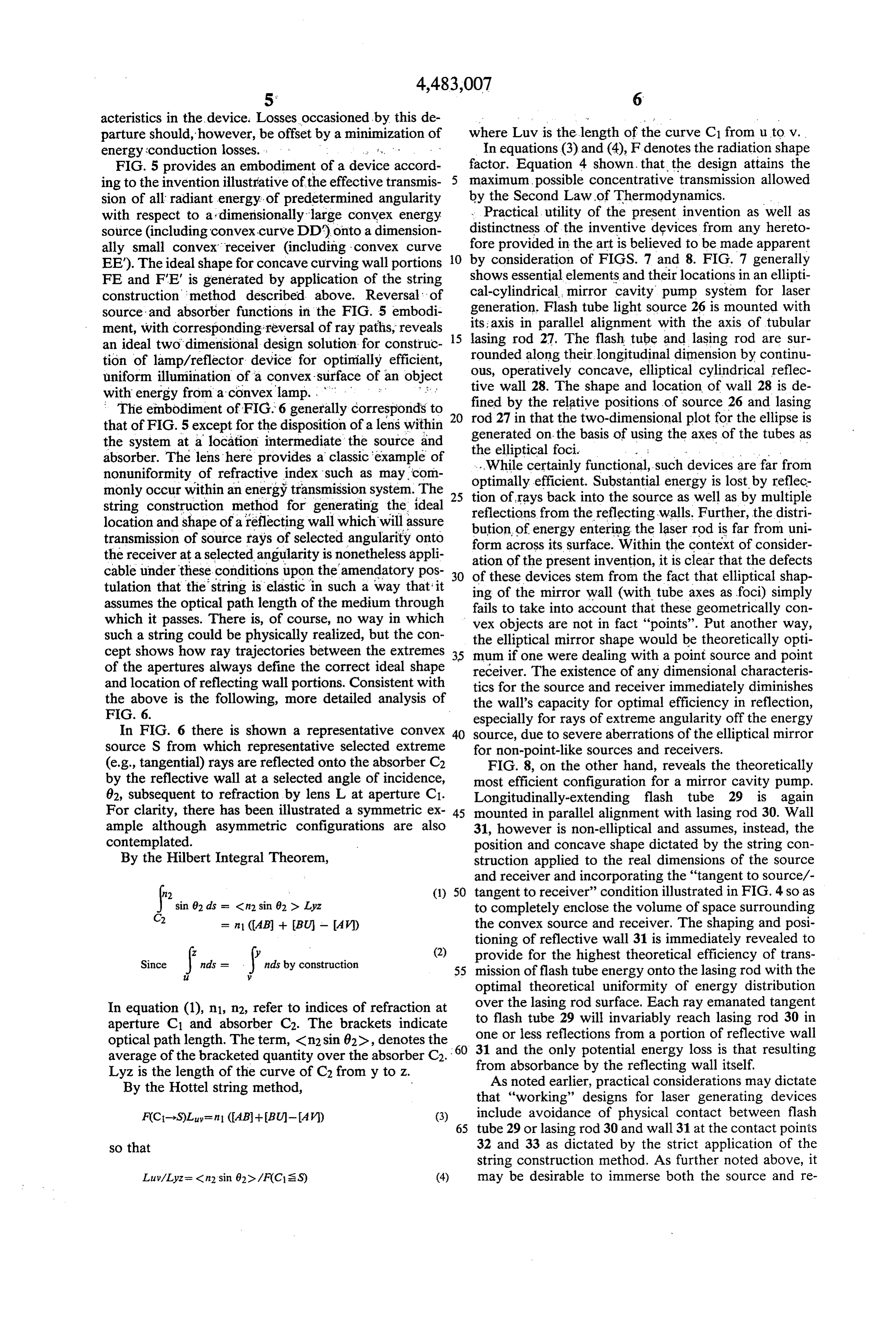
acteristics in the device. Losses occasioned by this de parture should, however, be offset by a minimization of where Luv is the length of the curve C1 from u to v. energy conduction losses. : ... x. In equations (3) and (4), F denotes the radiation shape FIG. 5 provides an embodiment of a device accord factor. Equation 4 shown, that the design attains the ing to the invention illustrative of the effective transmis maximum possible concentrative transmission allowed sion of all radiant energy of predetermined angularity by the Second Law of Thermodynamics. with respect to a dimensionally large convex energy Practical. utility of the present invention as well as source (including convex curve DD) onto a dimension distinctness of the inventive devices from any hereto ally small convex receiver (including convex curve O fore provided in the art is believed to be made apparent EE). The ideal shape for concave curving wall portions by consideration of FIGS. 7 and 8. FIG. 7 generally FE and FE is generated by application of the string shows essential elements and their locations in an ellipti construction method described above. Reversal of cal-cylindrical mirror cavity pump system for laser source and absorber functions in the FIG. 5 embodi generation. Flash tube light source 26 is mounted with ment, with corresponding reversal of ray paths, reveals 15 its; axis in parallel alignment with the axis of tubular an ideal two dimensional design solution for construc lasing rod 27. The flash tube and lasing rod are sur rounded along their longitudinal dimension by continu tion of lamp/reflector device for optimially efficient, ous, operatively concave, elliptical cylindrical reflec uniform illumination of a convex-surface of an object tive wall 28. The shape and location of wall 28 is de with energy from a convex lamp. . . . . is fined by the relative positions of source 26 and lasing The embodiment of FIG. 6 generally corresponds to rod 27 in that the two-dimensional plot for the ellipse is that of FIG. 5 except for the disposition of a lens within generated on the basis of using the axes of the tubes as the system at a location intermediate the source and the elliptical foci. . . . . .. . . . absorber. The lens here provides a classic example of ...While certainly functional, such devices are far from nonuniformity of refractive index such as may.com optimally efficient. Substantial energy is lost by reflec monly occur within an energy transmission system. The 25 tion of rays back into the source as well as by multiple string construction method for generating the ideal reflections from the reflecting walls. Further, the distri location and shape of a reflecting wall which will assure bution of energy entering the laser rod is far from uni transmission of source rays of selected angularity onto form across its surface. Within the context of consider the receiver at a selected angularity is nonetheless appli ation of the present invention, cable under these conditions upon the amendatory pos 30 of these devices stem from theitfact is clear that the defects that elliptical shap tulation that the string is elastic in such a way that it ing of the mirror wall (with tube axes as foci) simply assumes the optical path length of the medium through fails to take into account that these geometrically con which it passes. There is, of course, no way in which vex objects are not in fact "points'. Put another way, such a string could be physically realized, but the con the elliptical mirror shape would be theoretically opti cept shows how ray trajectories between the extremes 35 mum if one were dealing with a point source and point of the apertures always define the correct ideal shape receiver. The existence of any dimensional characteris and location of reflecting wall portions. Consistent with tics for the source and receiver immediately diminishes the above is the following, more detailed analysis of the wall's capacity for optimal efficiency in reflection, F.G. 6. especially for rays of extreme angularity off the energy In FIG. 6 there is shown a representative convex 40 source, due to severe aberrations of the elliptical mirror source S from which representative selected extreme for non-point-like sources and receivers. (e.g., tangential) rays are reflected onto the absorber C2 FIG. 8, on the other hand, reveals the theoretically by the reflective wall at a selected angle of incidence, most efficient configuration for a mirror cavity pump. 62, subsequent to refraction by lens L at aperture C1. Longitudinally-extending flash tube 29 is again For clarity, there has been illustrated a symmetric ex 45 mounted in parallel alignment with lasing rod 30. Wall ample although asymmetric configurations are also 31, however is non-elliptical and assumes, instead, the contemplated. position and concave shape dictated by the string con By the Hilbert Integral Theorem, struction applied to the real dimensions of the source and receiver and incorporating the "tangent to source/- n2 (1) 50 tangent to receiver” condition illustrated in FIG. 4 so as
sin 62 dis = <n2 sin 82 > Lyz to completely enclose the volume of space surrounding 2 = n.1 (AB - BU - A V1) the convex source and receiver. The shaping and posi tioning of reflective wall 31 is immediately revealed to
Since
inds = . nds by construction (2) provide for the highest theoretical efficiency of trans y 55 mission of flash tube energy onto the lasing rod with the optimal theoretical uniformity of energy distribution
In equation (1), n1, m2, refer to indices of refraction at overto the lasing rod surface. Each ray emanated tangent flash tube 29 will invariably reach lasing rod 30 in aperture C1 and absorber C2. The brackets indicate one or less optical path length. The term, <n2 sin 62), denotes the 60 31 and the reflections only from a portion of reflective wall potential energy loss is that resulting average of the bracketed quantity over the absorber C2. from absorbance by the reflecting wall itself. Lyz is the length of the curve of C2 from y to Z. As noted earlier, practical considerations may dictate By the Hottel string method, that “working' designs for laser generating devices FCC-S)Luyen (AB-BU-AV) (3) include avoidance of physical contact between flash 65 tube 29 or lasing rod 30 and wall 31 at the contact points so that 32 and 33 as dictated by the strict application of the string construction method. As further noted above, it may be desirable to immerse both the source and re
Page 7
ceiver in an energy transmitting refractive medium. first predetermined angle and impinging upon said re Proper selection of the medium on the basis of refrac flective wall portion are made to be incident upon said tive index relative to air or other surrounding medium receiver at a second predetermined angle, in a single and proper adjustment of the string construction reflection from said wall portion. method to account for the refractive index of the im 2. The device of claim 1 wherein said first predeter mersing medium allows construction of a device mined angle is tangent to said source and said second wherein reflectivity at the interface of the immersing predetermined angle-is tangent to said receiver. and surrounding media is provided according to princi 3. The device of claim 1 wherein said longitudinally ples of total internal reflectivity i.e. the surrounding extending source and receiver are circular in cross-sec media or volume being of lesser refractive index than 10 tion4. The and aligned on parallel axis.
device of claim 1 wherein said longitudinally the internal or immersing media or volume.
Numerous modifications and variations in the con extending source and receiver are circular in cross-sec struction of devices according to the above description tion and aligned on parallel axis, and said wall portion of the invention are expected to occur to those skilled in encloses the volume of space surrounding both said the art. Consequently only such limitations should be 15 source and receiver, the shape and position of said wall placed on the scope of the invention as appear in the portion with respect to said source and receiver being appended claims. such that extreme energy rays emanating from said What is claimed is: source along its length will be transmitted to and im 1. In a device for transmission of radiant energy from pinge upon said receiver directly or in one reflection a longitudinally-extending source having a convex sur 20 from said wall portion.
5. The device of claim 4 wherein said source is a face to a longitudinally-extending receiver having a convex surface wherein a longitudinally-extending wall pump lamp for a lasing rod and said receiver is said portion positioned adjacent either said source, or said lasing rod. . .
6. The device of claim 4 wherein said volume is filled receiver, or both said source and receiver, provides a means for reflecting radiant energy emanating from said 25 with a medium having a selected index of refraction. source onto said receiver, the improvement comprising 7. The device of claim 6 wherein said reflective wall a non-imaging concentrator which includes a concave fillingportion comprises the interface between said medium reflective wall portion which is non-elliptical in two said volume and having a given index of refrac dimensional cross-section and shaped and positioned tion and a second medium of lesser refractive index in with respect to said receiver and source so that energy 30 optical contact with saids medium
filling
said volume.
rays emanating from said source along its length at a
Provenance
- Collection
- Cited prior art
- Original PDF
- patentimages.storage.googleapis.com →
- Filed
- 1981-07-10
- Pages
- 7
- Method
- pdftotext (the PDF's own text layer) + pdftoppm 300dpi page scans
- Source
- Google Patents bibliographic record
- Granted
- 1984-11-13
- Inventors
- Roland Winston; University of Chicago
- Transcribed from
- patentimages.storage.googleapis.com →