patent · US4742225
Elliptical cylinder light collector for photosimulable phosphor imaging apparatus
3 May 1988
Page 1 — bibliographic record
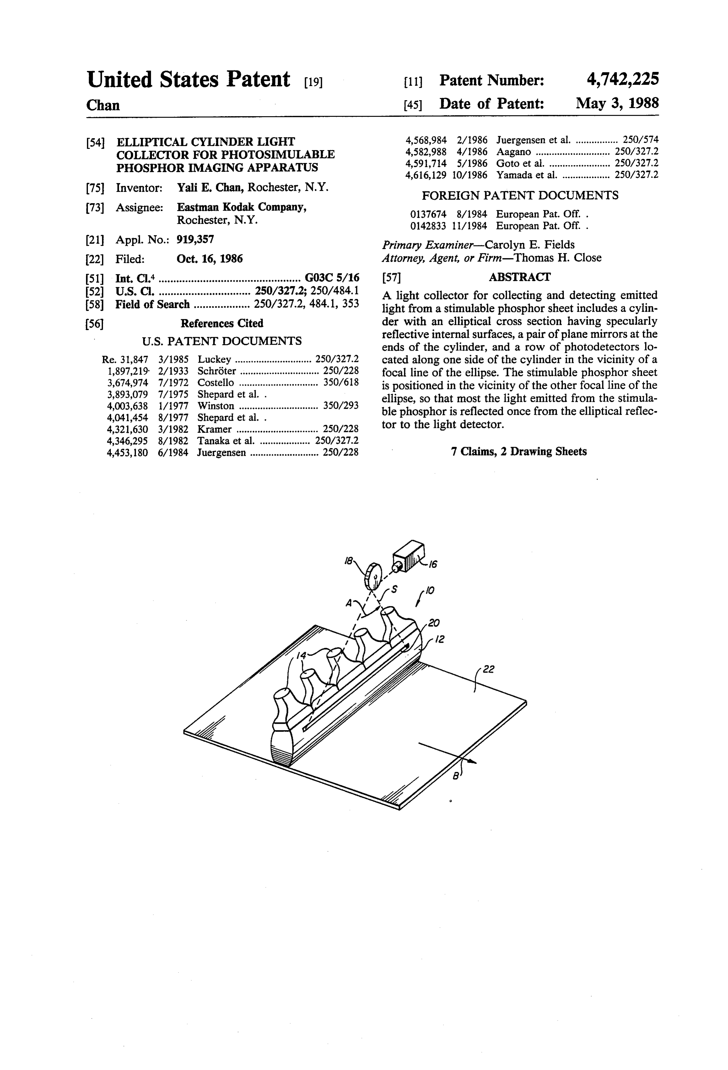
United States Patent (19) 11 Patent Number: 4,742,225 Chan 45 Date of Patent: May 3, 1988 54 ELLIPTICAL CYLNDER LIGHT 4,568,984 2/1986 Juergensen et al. ................ 250/574 COLLECTOR FORPHOTOSIMULABLE 4,582,988 4/1986 Aagano ............... . 250/327.2 PHOSPHOR MAGNGAPPARATUS 4,591,714 5/1986 Goto et al. ....................... 250/327.2
(75. Inventor: Yali E. Chan, Rochester, N.Y. FOREIGN PATENT DOCUMENTS 73) Assignee: Eastman Kodak Company, 0137674 8/1984 European Pat. Off. . Rochester, N.Y. 0142833 11/1984 European Pat. Off. .
(21) Appl. No.: 919,357 Primary Examiner-Carolyn E. Fields 22 Filed: Oct. 16, 1986 Attorney, Agent, or Firm-Thomas H. Close 51) Int. Cl."................................................ G03C5/16 57 ABSTRACT 52 U.S. C. ............................... 250/327.2; 250/484.1 A light collector for collecting and detecting emitted 58 Field of Search ................... 250/327.2, 484.1, 353 light from a stimulable phosphor sheet includes a cylin 56) References Cited der with an elliptical cross section having specularly
ends of the cylinder, and a row of photodetectors lo
Re. 31,847 3/1985 Luckey ............................. 250/327.2 cated along one side of the cylinder in the vicinity of a 1,897,219 2/1933 Schröter .............................. 250/228 focal line of the ellipse. The stimulable phosphor sheet 3,674,974 7/1972 Costello .............................. 350/618 is positioned in the vicinity of the other focal line of the 3,893,079 7/1975 Shepard et al. . ellipse, so that most the light emitted from the stimula 4,003,638 1/1977 Winston .............................. 350/293 ble phosphor is reflected once from the elliptical reflec 4,041,454 8/1977 Shepard et al. . tor to the light detector.
4,321,630 3/1982 Kramer ............................... 250/228 4,346,295 8/1982 Tanaka et al. ... 250/327.2 4,453,180 6/1984 Juergensen .......................... 250/228 7 Claims, 2 Drawing Sheets
Page 2
Drawing sheet — no readable text.
Page 3
Drawing sheet — no readable text.
Page 4
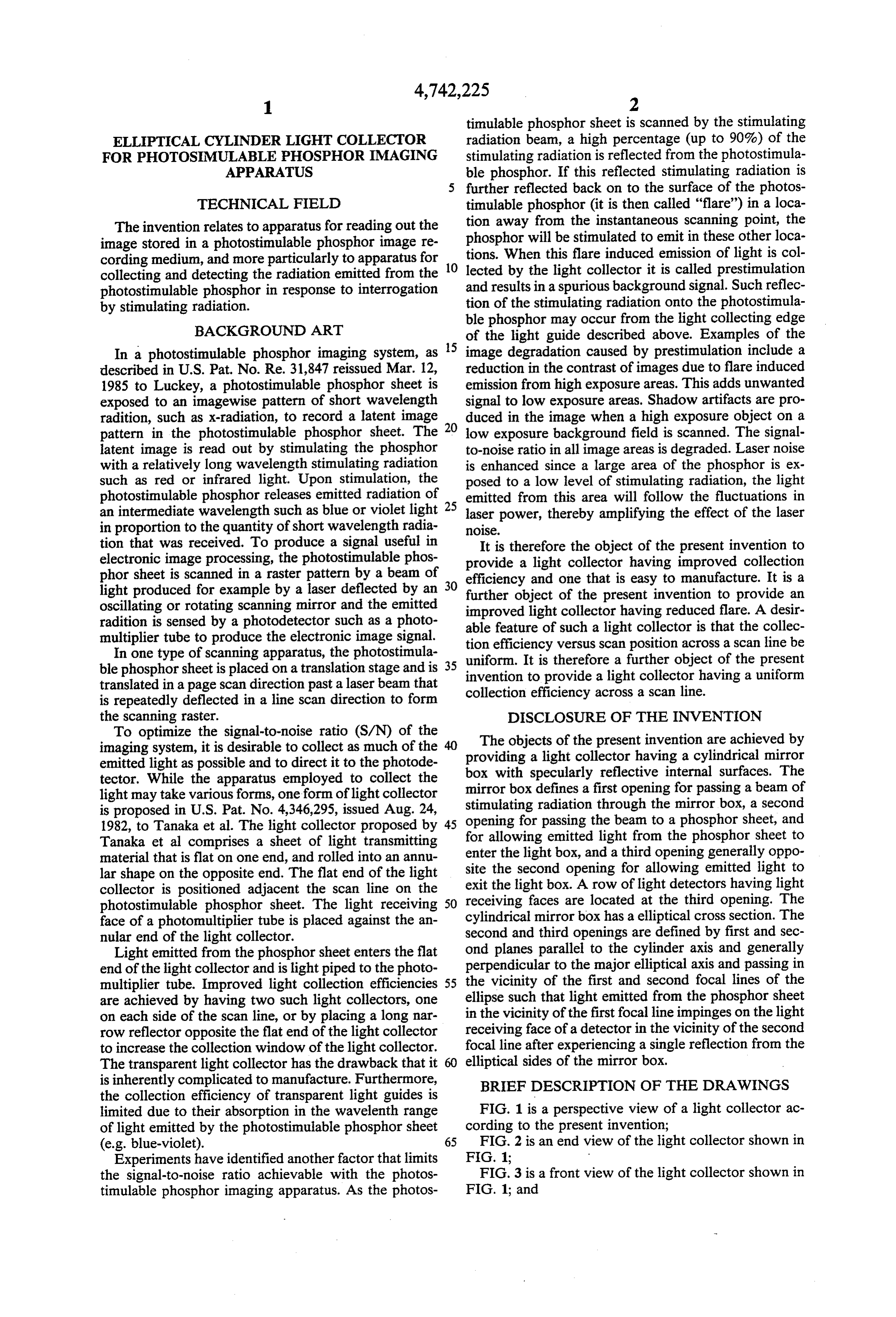
timulable phosphor sheet is scanned by the stimulating
ELLPTICAL CYLNDER LIGHT COLLECTOR radiation beam, a high percentage (up to 90%) of the FOR PHOTOSMULABLE PHOSPHOR IMAGING stimulating radiation is reflected from the photostimula APPARATUS ble phosphor. If this reflected stimulating radiation is further reflected back on to the surface of the photos
TECHNICAL FIELD timulable phosphor (it is then called "flare") in a loca The invention relates to apparatus for reading out the tion away from the instantaneous scanning point, the image stored in a photostimulable phosphor image re phosphor will be stimulated to emit in these other loca cording medium, and more particularly to apparatus for 10 tions. When this flare induced emission of light is col collecting and detecting the radiation emitted from the lected by the light collector it is called prestimulation photostimulable phosphor in response to interrogation and results in a spurious background signal. Such reflec by stimulating radiation. tion of the stimulating radiation onto the photostimula ble phosphor may occur from the light collecting edge
BACKGROUND ART of the light guide described above. Examples of the In a photostimulable phosphor imaging system, as 5 image degradation caused by prestimulation include a described in U.S. Pat. No. Re. 31,847 reissued Mar. 12, reduction in the contrast of images due to flare induced 1985 to Luckey, a photostimulable phosphor sheet is emission from high exposure areas. This adds unwanted exposed to an imagewise pattern of short wavelength signal to low exposure areas. Shadow artifacts are pro radition, such as x-radiation, to record a latent image duced in the image when a high exposure object on a pattern in the photostimulable phosphor sheet. The 20 low exposure background field is scanned. The signal latent image is read out by stimulating the phosphor to-noise ratio in all image areas is degraded. Laser noise with a relatively long wavelength stimulating radiation is enhanced since a large area of the phosphor is ex such as red or infrared light. Upon stimulation, the posed to a low level of stimulating radiation, the light photostimulable phosphor releases emitted radiation of 25 emitted from this area will follow the fluctuations in an intermediate wavelength such as blue or violet light laser power, thereby amplifying the effect of the laser in proportion to the quantity of short wavelength radia noise.
tion that was received. To produce a signal useful in It is therefore the object of the present invention to electronic image processing, the photostimulable phos provide a light collector having improved collection phor sheet is scanned in a raster pattern by a beam of 30 efficiency and one that is easy to manufacture. It is a light produced for example by a laser deflected by an oscillating or rotating scanning mirror and the emitted further object of the present invention to provide an radition is sensed by a photodetector such as a photo able featurelight improved collector having reduced flare. A desir multiplier tube to produce the electronic image signal. tion efficiency versusascan of such light collector is that the collec position across a scan line be
In one type of scanning apparatus, the photostimula uniform. It is therefore a further object of the present ble phosphor sheet is placed on a translation stage and is 35 invention to provide a light collector translated in a page scan direction past a laser beam that collection efficiency across a scan line.having a uniform is repeatedly deflected in a line scan direction to form the scanning raster. DISCLOSURE OF THE INVENTION To optimize the signal-to-noise ratio (S/N) of the The objects of the present invention are achieved by imaging system, it is desirable to collect as much of the 40 providing a light collector having a cylindrical mirror emitted light as possible and to direct it to the photode box with specularly reflective internal surfaces. The tector. While the apparatus employed to collect the mirror box defines a first opening for passing a beam of light may take various forms, one form of light collector stimulating radiation through is proposed in U.S. Pat. No. 4,346,295, issued Aug. 24, opening for passing the beam the to a mirror box, a second phosphor sheet, and 1982, to Tanaka et al. The light collector proposed by 45
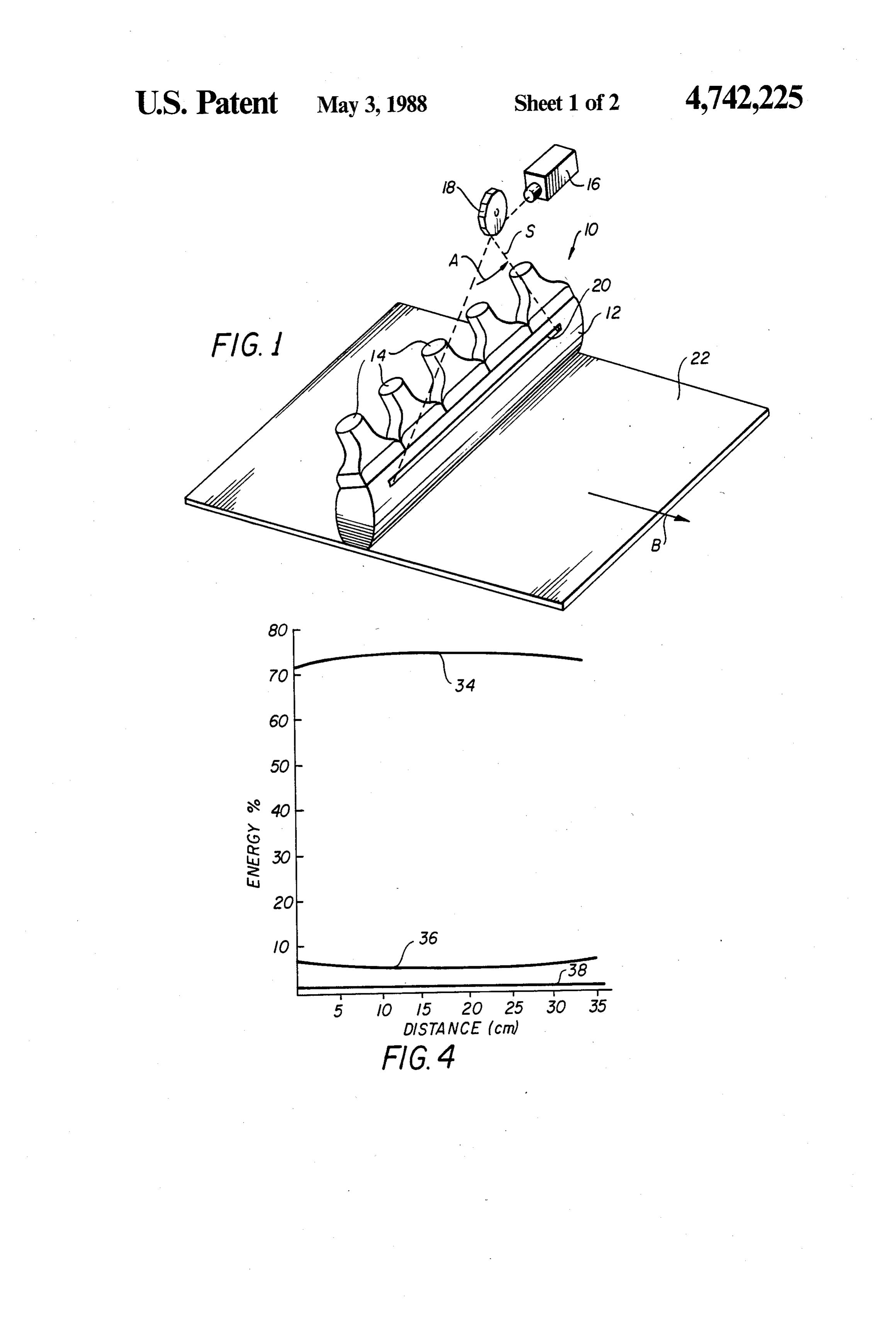
Tanaka et al comprises a sheet of light transmitting for allowing emitted light from the phosphor sheet to material that is flat on one end, and rolled into an annu enter the light box, and a third opening generally oppo lar shape on the opposite end. The flat end of the light exit site the second opening for allowing emitted light to collector is positioned adjacent the scan line on the the light box. A row of light detectors having light photostimulable phosphor sheet. The light receiving 50 receiving faces are located at the third opening. The face of a photomultiplier tube is placed against the an cylindrical mirror box has a elliptical cross section. The nular end of the light collector. second and third openings are defined by first and sec Light emitted from the phosphor sheet enters the flat ond planes parallel to the cylinder axis and generally end of the light collector and is light piped to the photo perpendicular to the major elliptical axis and passing in multiplier tube. Improved light collection efficiencies 55 the vicinity of the first and second focal lines of the are achieved by having two such light collectors, one ellipse such that light emitted from the phosphor sheet on each side of the scan line, or by placing a long nar in the vicinity of the first focal line impinges on the light row reflector opposite the flat end of the light collector receiving face of a detector in the vicinity of the second to increase the collection window of the light collector. focal line after experiencing a single reflection from the The transparent light collector has the drawback that it elliptical sides of the mirror box. is inherently complicated to manufacture. Furthermore, the collection efficiency of transparent light guides is BRIEF DESCRIPTION OF THE DRAWINGS limited due to their absorption in the wavelenth range FIG. 1 is a perspective view of a light collector ac of light emitted by the photostimulable phosphor sheet cording to the present invention;
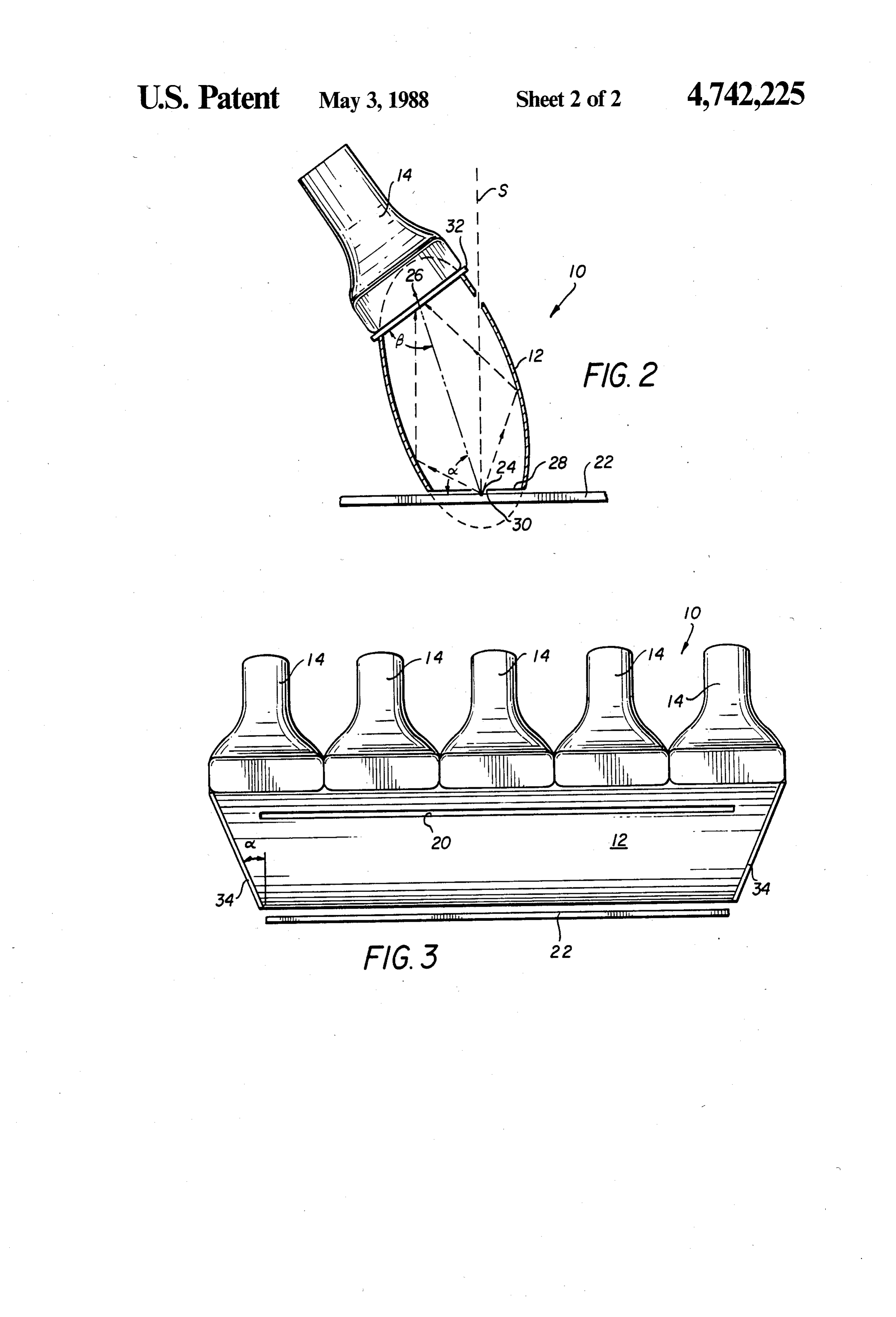
(e.g. blue-violet). 65 FIG. 2 is an end view of the light collector shown in Experiments have identified another factor that limits FIG. 1;
the signal-to-noise ratio achievable with the photos FIG. 3 is a front view of the light collector shown in timulable phosphor imaging apparatus. As the photos FIG. 1; and
Page 5
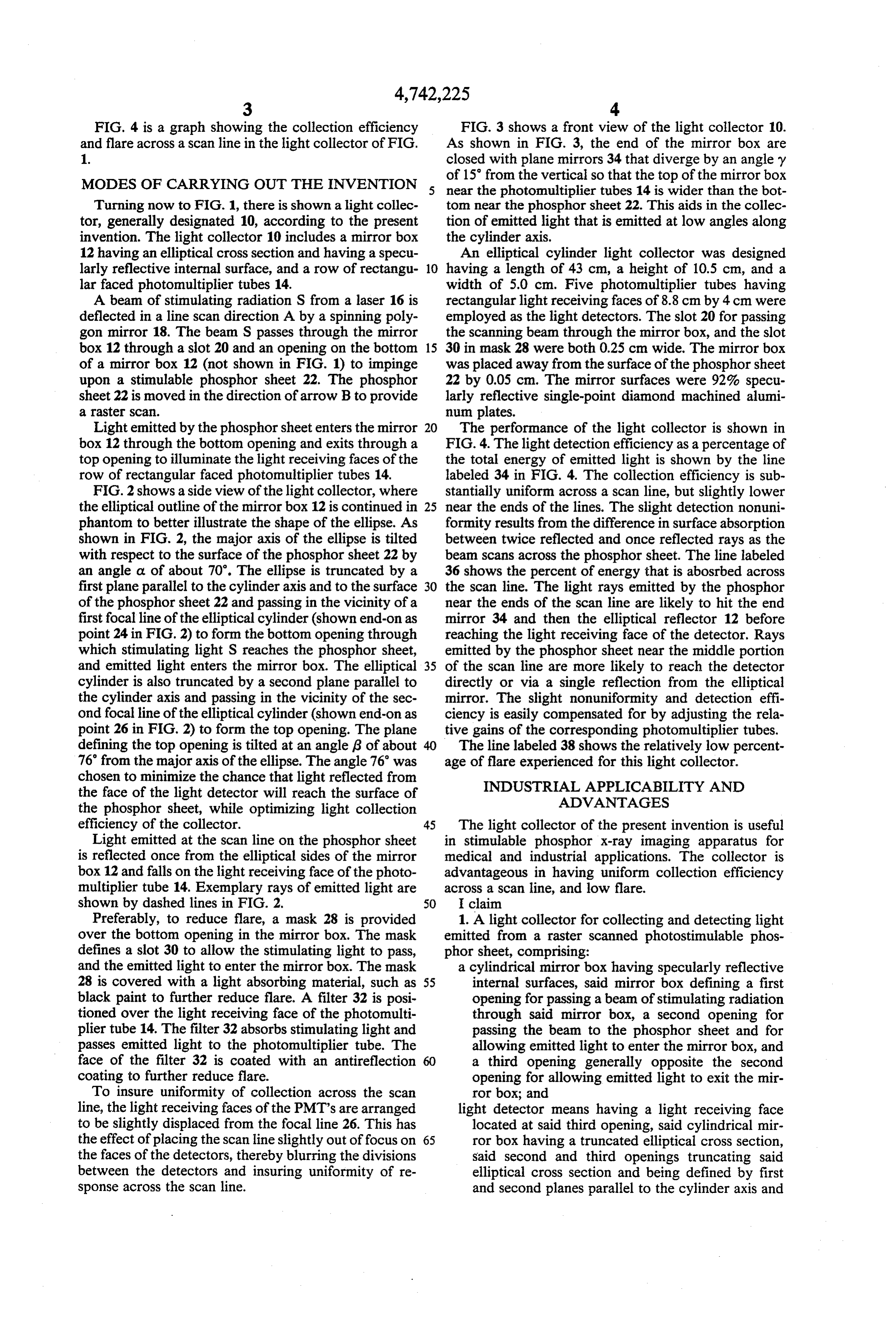
FIG. 4 is a graph showing the collection efficiency FIG. 3 shows a front view of the light collector 10. and flare across a scan line in the light collector of FIG. As shown in FIG. 3, the end of the mirror box are 1. closed with plane mirrors 34 that diverge by an angley of 15 from the vertical so that the top of the mirror box
MODES OF CARRYING OUT THE INVENTION 5 near the photomultiplier tubes 14 is wider than the bot Turning now to FIG. 1, there is shown a light collec tom near the phosphor sheet 22. This aids in the collec tor, generally designated 10, according to the present tion of emitted light that is emitted at low angles along invention. The light collector 10 includes a mirror box the cylinder axis.
12 having an elliptical cross section and having a specu An elliptical cylinder light collector was designed larly reflective internal surface, and a row of rectangu 10 having a length of 43 cm, a height of 10.5 cm, and a lar faced photomultiplier tubes 14. width of 5.0 cm. Five photomultiplier tubes having A beam of stimulating radiation S from a laser 16 is rectangular light receiving faces of 8.8 cm by 4 cm were deflected in a line scan direction A by a spinning poly employed as the light detectors. The slot 20 for passing gon mirror 18. The beam S passes through the mirror the scanning beam through the mirror box, and the slot box 12 through a slot 20 and an opening on the bottom 15 30 in mask 28 were both 0.25 cm wide. The mirror box of a mirror box 12 (not shown in FIG. 1) to impinge was placed away from the surface of the phosphor sheet upon a stimulable phosphor sheet 22. The phosphor 22 by 0.05 cm. The mirror surfaces were 92% specu sheet 22 is moved in the direction of arrow B to provide larly reflective single-point diamond machined alumi a raster Scan. num plates.
Light emitted by the phosphor sheet enters the mirror 20 The performance of the light collector is shown in box 12 through the bottom opening and exits through a FIG. 4. The light detection efficiency as a percentage of top opening to illuminate the light receiving faces of the the total energy of emitted light is shown by the line row of rectangular faced photomultiplier tubes 14. labeled 34 in FIG. 4. The collection efficiency is sub FIG. 2 shows a side view of the light collector, where stantially uniform across a scan line, but slightly lower the elliptical outline of the mirror box 12 is continued in 25 near the ends of the lines. The slight detection nonuni phantom to better illustrate the shape of the ellipse. As formity results from the difference in surface absorption shown in FIG. 2, the major axis of the ellipse is tilted between twice reflected and once reflected rays as the with respect to the surface of the phosphor sheet 22 by beam scans across the phosphor sheet. The line labeled an angle a of about 70. The ellipse is truncated by a 36 shows the percent of energy that is abosrbed across first plane parallel to the cylinder axis and to the surface 30 the scan line. The light rays emitted by the phosphor of the phosphor sheet 22 and passing in the vicinity of a near the ends of the scan line are likely to hit the end first focal line of the elliptical cylinder (shown end-on as mirror 34 and then the elliptical reflector 12 before point 24 in FIG. 2) to form the bottom opening through reaching the light receiving face of the detector. Rays which stimulating light S reaches the phosphor sheet, emitted by the phosphor sheet near the middle portion and emitted light enters the mirror box. The elliptical 35 of the scan line are more likely to reach the detector cylinder is also truncated by a second plane parallel to directly or via a single reflection from the elliptical the cylinder axis and passing in the vicinity of the sec mirror. The slight nonuniformity and detection effi ond focal line of the elliptical cylinder (shown end-on as ciency is easily compensated for by adjusting the rela point 26 in FIG. 2) to form the top opening. The plane tive gains of the corresponding photomultiplier tubes. defining the top opening is tilted at an angle 6 of about The line labeled 38 shows the relatively low percent 76 from the major axis of the ellipse. The angle 76 was age of flare experienced for this light collector. chosen to minimize the chance that light reflected from INDUSTRIAL APPLICABILITY AND the face of the light detector will reach the surface of ADVANTAGES the phosphor sheet, while optimizing light collection efficiency of the collector. 45 The light collector of the present invention is useful Light emitted at the scan line on the phosphor sheet in stimulable phosphor X-ray imaging apparatus for is reflected once from the elliptical sides of the mirror medical and industrial applications. The collector is box 12 and falls on the light receiving face of the photo advantageous in having uniform collection efficiency multiplier tube 14. Exemplary rays of emitted light are across a scan line, and low flare.
shown by dashed lines in FIG. 2. 50 I claim
Preferably, to reduce flare, a mask 28 is provided 1. A light collector for collecting and detecting light over the bottom opening in the mirror box. The mask emitted from a raster scanned photostimulable phos defines a slot 30 to allow the stimulating light to pass, phor sheet, comprising:
and the emitted light to enter the mirror box. The mask a cylindrical mirror box having specularly reflective 28 is covered with a light absorbing material, such as 55 internal surfaces, said mirror box defining a first black paint to further reduce flare. A filter 32 is posi opening for passing a beam of stimulating radiation tioned over the light receiving face of the photomulti through said mirror box, a second opening for plier tube 14. The filter 32 absorbs stimulating light and passing the beam to the phosphor sheet and for passes emitted light to the photomultiplier tube. The allowing emitted light to enter the mirror box, and face of the filter 32 is coated with an antireflection 60 a third opening generally opposite the second coating to further reduce flare. opening for allowing emitted light to exit the mir To insure uniformity of collection across the scan ror box; and line, the light receiving faces of the PMT's are arranged light detector means having a light receiving face to be slightly displaced from the focal line 26. This has located at said third opening, said cylindrical mir the effect of placing the scan line slightly out of focus on 65 ror box having a truncated elliptical cross section, the faces of the detectors, thereby blurring the divisions said second and third openings truncating said between the detectors and insuring uniformity of re elliptical cross section and being defined by first sponse across the scan line. and second planes parallel to the cylinder axis and
Page 6
lying at 70 and 76 respectively to the major ellip 4. The light collector claimed in claim 1, further tical axis, and passing in the vicinity of first and including an optical filter for absorbing stimulating second focal lines of the ellipse such that light radiation, and transmitting emitted radiation located between said third opening and said light receiving face emitted from the phosphor sheet in the vicinity of 5 of said light first focal line impinges on said light receiving face detector means.
5. The light collector claimed in claim 1, further of said detector means in the vicinity of said second including focal line after experiencing a single reflection. an antireflective coating on said optical filter. 6. The light collector claimed in claim 1, wherein said 2. The light collector claimed in claim 1, wherein the light detector means comprises a row of photomulti ends of said cylindrical mirror box are covered with 10 plier tubes having rectangular light receiving faces. plane mirrors. 7. The light collector claimed in claim 1, further 3. The light collector claimed in claim 2, wherein said comprising a mask located over said second opening, plane mirrors are arranged at an angle of 15 with re said mask defining a slit extending parallel with and in spect to the vertical such that said third opening is the vicinity of said first
focal line.
Provenance
- Collection
- Cited prior art
- Original PDF
- patentimages.storage.googleapis.com →
- Filed
- 1986-10-16
- Pages
- 6
- Method
- pdftotext (the PDF's own text layer) + pdftoppm 300dpi page scans
- Source
- Google Patents bibliographic record
- Granted
- 1988-05-03
- Inventors
- Yali E. Chan; Eastman Kodak Co
- Transcribed from
- patentimages.storage.googleapis.com →