patent · US4003638
Radiant energy collection
18 January 1977
Page 1 — bibliographic record
United States Patent to 11 4,003,638 Winston (45) "Jan. 18, 1977 54 RADIANT ENERGY COLLECTION (56) References Cited (75) Inventor: Roland Winston, Chicago, Ill. UNITED STATES PATENTS 980,505 l/9 Emmet .............................. 126/27 (73) Assignee: The University of Chicago, Chicago, 3,923,381 12/1975 Winston ............................ 350/293
Primary Examiner-Edward S. Bauer * Notice: The portion of the term of this Assistant Examiner-F. L. Evans patent subsequent to Dec. 2, 1992, Attorney, Agent, or Firm-Merriam, Marshall, Shapiro
Disclosed are non-imaging systems and devices for (21 Appl. No.: 613,577 collection and concentration of electromagnetic en ergy and particularly solar energy including one or more longitudinally-extending, generally trough
Related U.S. Application Data shaped bodies having curving inner reflective walls for (63) Continuation of Ser. No. 429,161, Dec. 28, 1973, Pat. concentration of energy from a relatively large en No. 3,923,381. trance aperture toward a relatively small exit aperture. Solar energy concentrators of the invention include 52 U.S. Cl. ............................... 350/293; 126/271; energy traps and collect and concentrate substantial 350/294 . amounts of direct solar energy, even at solstice, without (51 int. Cl'........................................... G02B 5/10 substantial diurnal tracking.
350/293, 294, 299, 190, 310 7 Claims, 19 Drawing Figures
Page 2
Drawing sheet — no readable text.
Page 3
Drawing sheet — no readable text.
Page 4
Drawing sheet — no readable text.
Page 5
Drawing sheet — no readable text.
Page 6
Drawing sheet — no readable text.
Page 7
Drawing sheet — no readable text.
Page 8
Drawing sheet — no readable text.
Page 9
ment generally provide lowest factors of concentration.
RADANT ENERGY COLLECTION Thus, Tabor, infra concludes that the maximum con centration available in a stationary system (i.e., one
This is a continuation of application Ser. No. requiring only seasonal tracking) is on the order of 3 or
3,923,381. Non-imaging light funnels having utility in collection BACKGROUND OF THE INVENTION of light from high energy particles and having a greater concentration capacity than imaging systems have been
The present invention relates generally to electro proposed by the inventor and his collaborators in ear magnetic energy collection and more particularly to O lier publications, i.e., Review of Scientific Instruments, devices useful in the collection and utilization of radi Vol. 37, No. 8, pp. 1094-5 (1966), ibid., Vol.39, No. ant energy from solar and other sources. 3, pp. 419-20 (1968), ibid., Vol.39, No. 8, pp. 1217-8 The prior art has proposed numerous devices for (1968), and J. Opt.Soc. Am..., Vol. 60, No. 2, pp. 245-7 detection of electromagnetic energy (e.g., infrared (1970). The inventor also noted the similarity between scanners, detectors of light from high energy particles, 15 such funnels and the geometry of retinal cones in J. and the like) and for collection of such energy (e.g., Opt. Soc. Am..., Vol. 61, No. 8, pp. 1 120-1 (1971). microwave antennas, solar collectors, and the like) and Basically, the above publications dealt with proposals is particularly rich in suggestions of systems for collec for "ideal', conical-shaped, light collectors which ap tion and utilization of solar energy. proach an finumber equal to 0.5, a physically unrealiza Notwithstanding the voluminous proposals of the art, ble limit for lens systems. The field of acceptance of among the basic, and as yet inadequately resolved, conical collectors therein proposed may be represented problems inherent in the efficient utilization of solar by a right circular cone having a gradually diminishing energy are avoidance of energy loss through re-radia (over about 1) external boundary cut-off. tion (i.e., energy conservation) and avoidance of intri SUMMARY OF THE INVENTION cate, and hence costly, apparatus for tracking the sun 25 in its apparent daily motion through the celestial According to the present invention a non-imaging sphere. system of exceptional efficiency is provided for the A typical attempt to solve solar energy conservation collection and concentration of electromagnetic en problems involves providing selective coatings on en ergy. Comprehended by the invention are longitudi ergy absorbing surfaces as well as elaborate insulation 30 nally extending, generally trough-shaped collection of the particular "trap' employed for the utilization of structures including opposed inner reflective surfaces collected energy. U.S. Pat. No. 3,277,884, for example, which function to guide and concentrate radiant energy illustrates such a scheme. impinging upon a relatively large entrance opening Another common manner of dealing with energy toward - and if desired, through - a relatively small ... conservation involves including in the collection 35 exit opening at which there may be disposed a trap for scheme reflective or refractive concentration appara detection or utilization of the concentrated energy. tus to permit collection of solar energy impinging upon Preferred embodiments of the structures of the present a relatively large area and focusing of collected energy invention possess an elliptical conical field of accep toward a relatively small area of utilization. Typical tance exhibiting an extremely sharp external boundary schemes proposing use of reflector concentrators are 40 cut-off.
illustrated in U.S. Pat. Nos. 1814,897, 3,200,820 and It is contemplated that embodiments of the present 3,217,702, for example. ("Shadowing' effects encoun invention may be most effectively employed in the tered in disposing an energy utilization body in path of collection and utilization of solar energy to provide for sunlight impinging upon reflectors are to some extent high energy concentration (and hence achievement of avoided through use of off-axis reflectors, as in U.S. 45 high temperatures and optimal energy conservation) Pat. Nos. 3,052,229, 3,613,659 and Tabor, “Stationary with minimal solar tracking.
Mirror Systems for Solar Collectors' Solar Energy, Further aspects and advantages of the present inven Vol. II, No. 3-4, pp. 27 et seq. (1958)). Typical lens tion will become apparent upon consideration of the systems for solar concentration are illustrated in U.S. following description thereof, reference being made of Pat. No. 3,125,091 and Meinel et al., “Physics Looks at SO the following drawing.
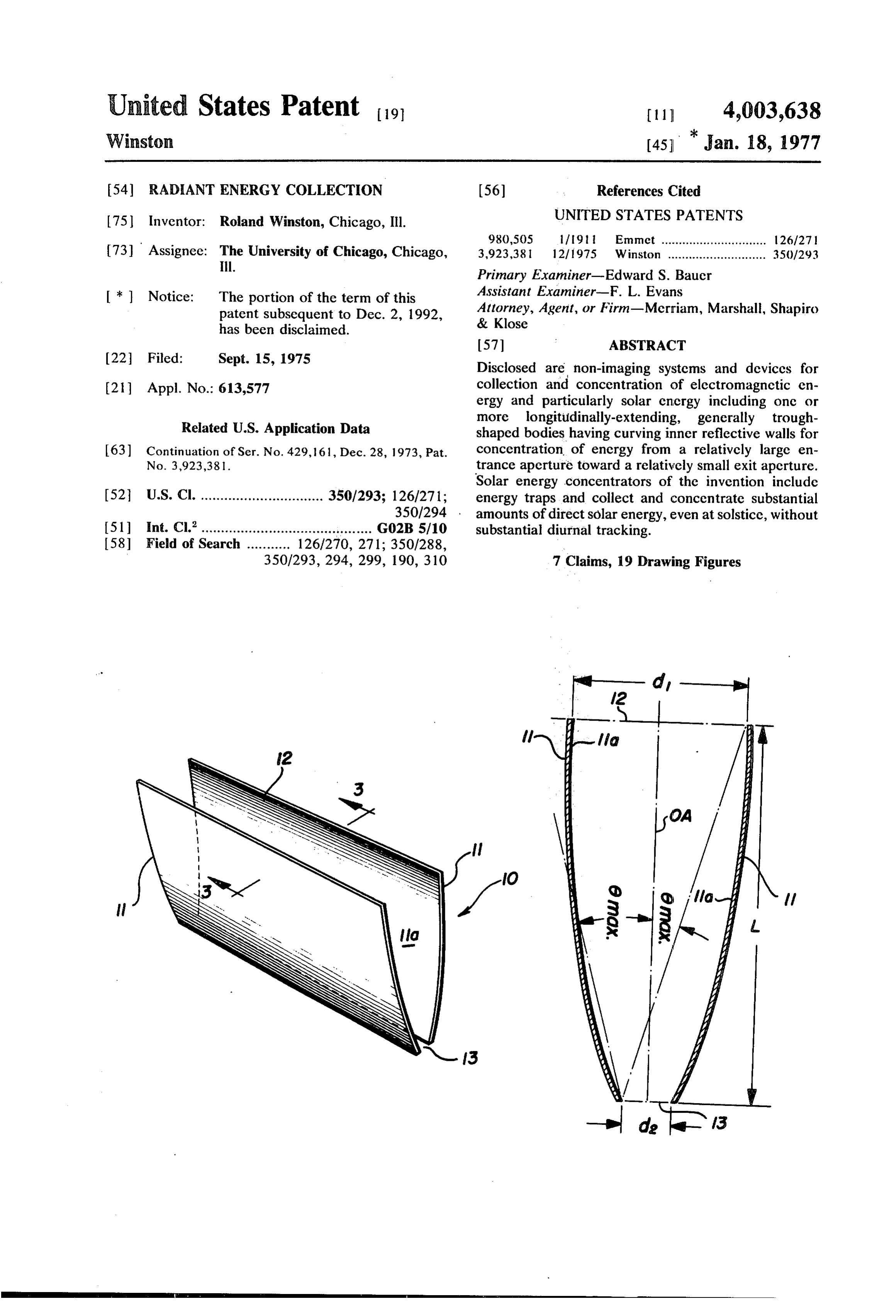
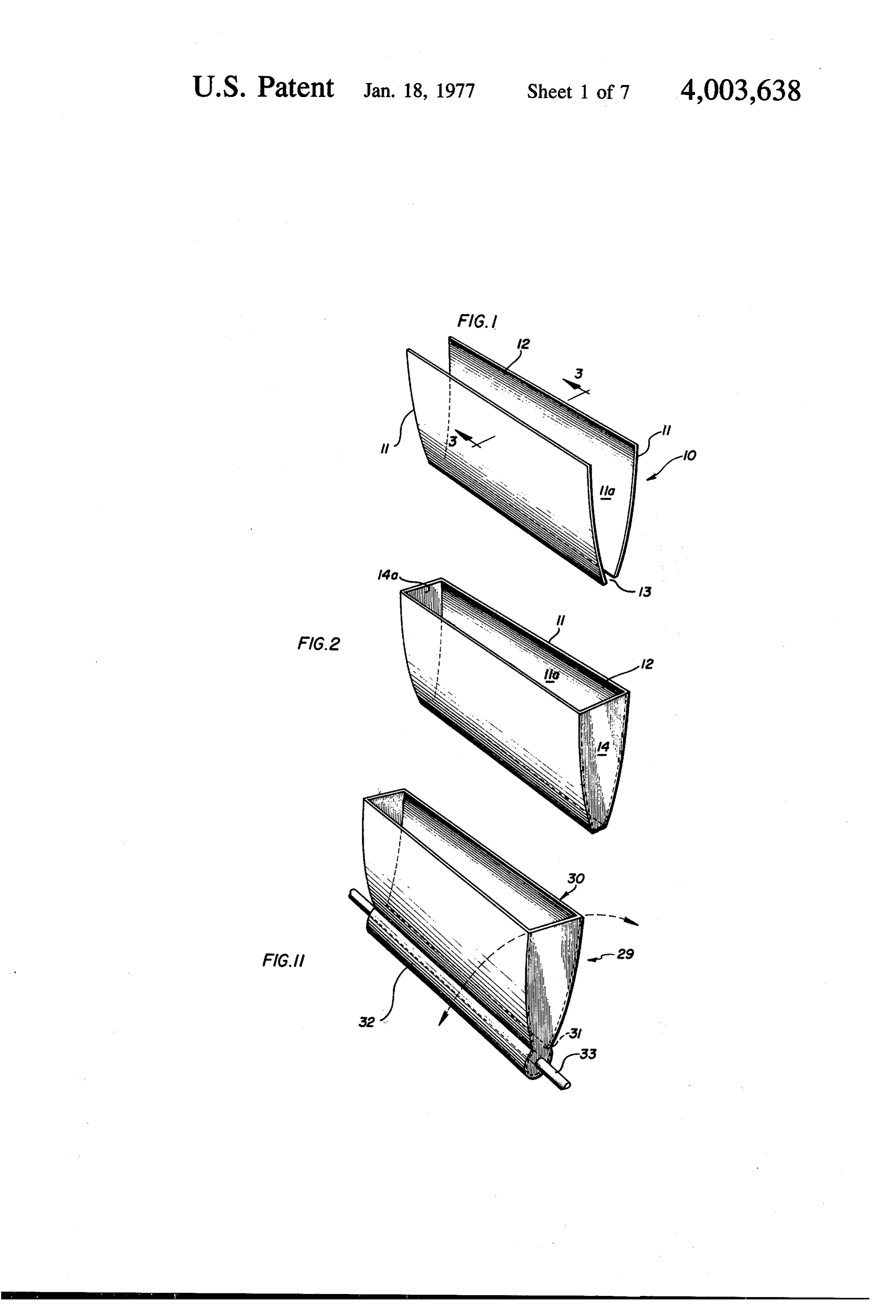
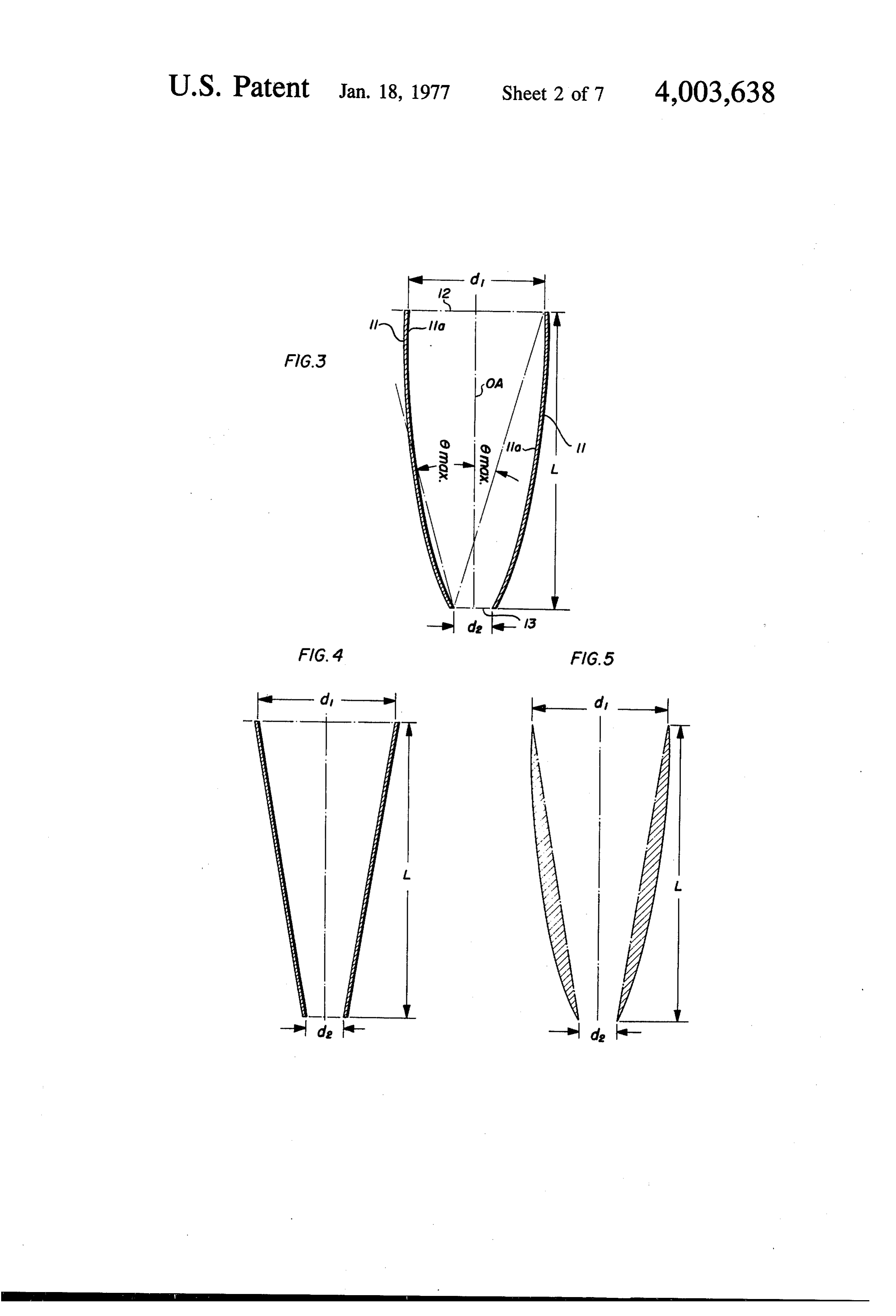
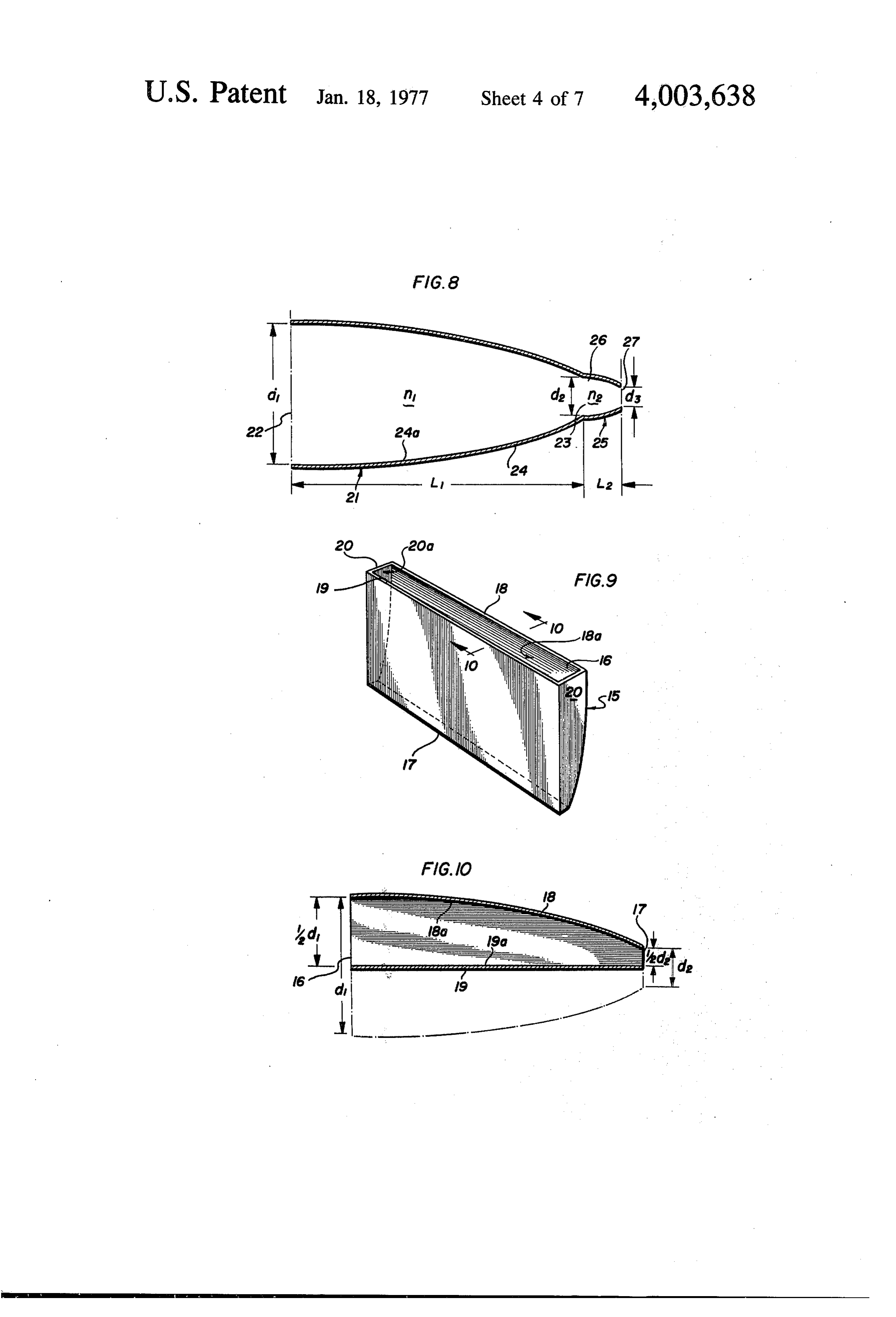
Solar Energy' Physics Today, Vol. 25, pp. 684 et seq. BRIEF DESCRIPTION OF THE DRAWING (1972). All of the mirroring and lens systems proposed above are basically imaging systems wherein solar en FIGS. 1 and 2 are schematic representations of radi ergy is reflected or refracted to a system focal point at ant energy collection troughs of the present invention. which the “concentrated' energy is utilized for heating 55 FIG. 3 is a transverse sectional view taken along line or power generation. 3-3 of FIG. 2.
Among the solutions proposed for avoidance of diur FIG. 4 is a transverse sectional view of a straight nal solar tracking is the provision of huge, but margin sided collection trough.
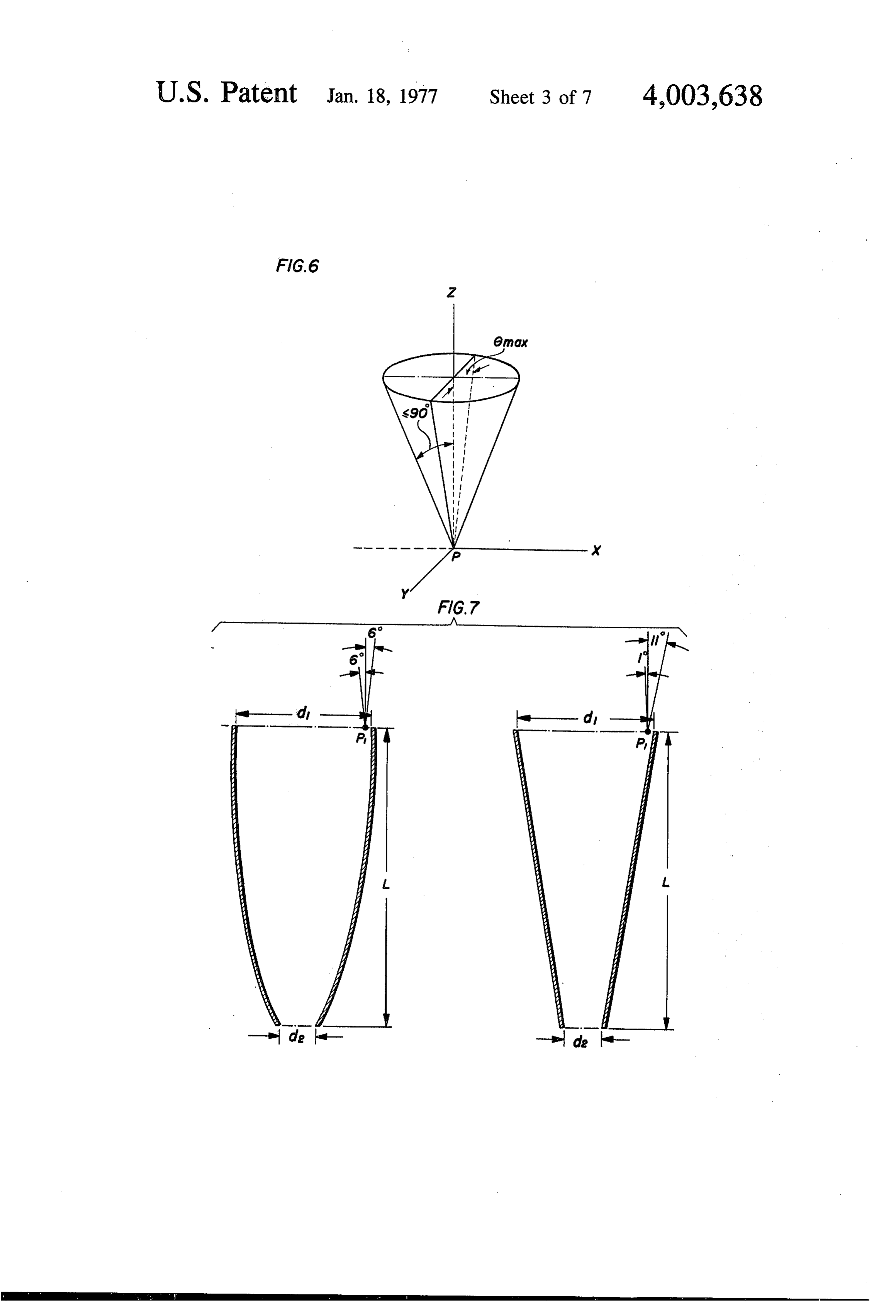
ally efficient, mirrored surfaces such as shown in U.S. FIG. 5 is a composite transverse sectional view of Pat. No. 3, 179, 105. 60 collection troughs including troughs of the invention. None of the prior art systems has adequately solved FIG. 6 is a graphic representation of the field of ac the problems of energy conservation and solar tracking ceptance of a collection trough as shown in FIGS 1-3. and, to a degree, solution of one problem often tends to FIG. 7 is a comparative graphic representation of enlarge the difficulties posed by the other. This is to say relative fields of acceptance. that systems permitting solar concentration by large 65 FIG. 8 is a cross sectional view of an alternative em factors generally will require the most careful and fre bodiment of the invention.
quent diurnal adjustments for solar tracking. Con FIG. 9 is a schematic representation of another alter versely, systems requiring little or no diurnal adjust native embodiment of the invention.
Page 10
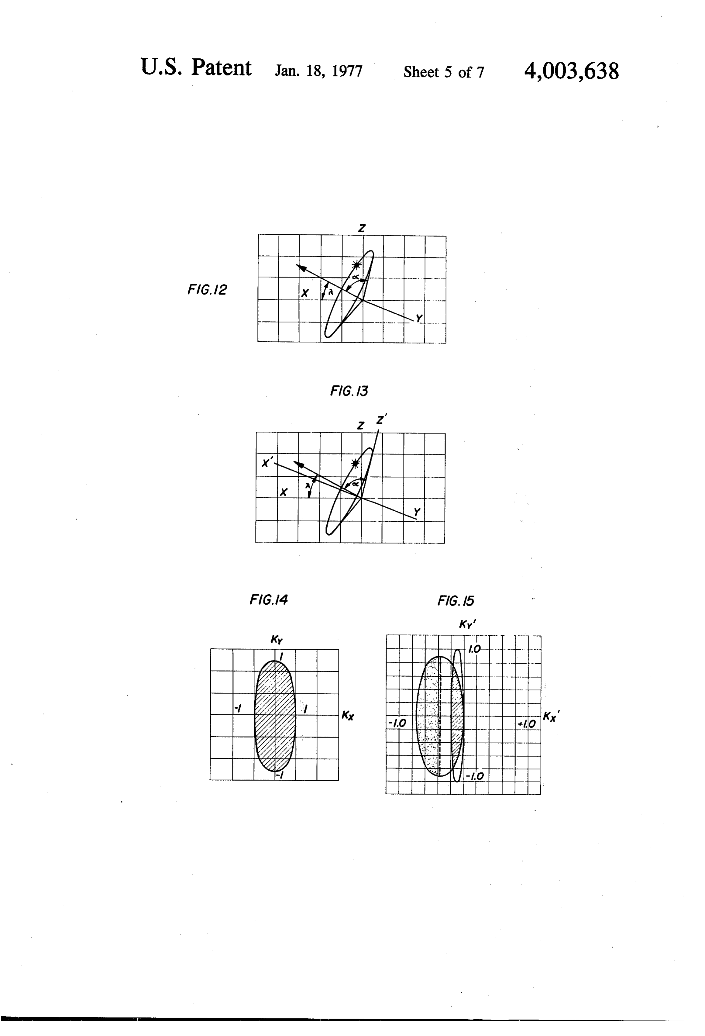
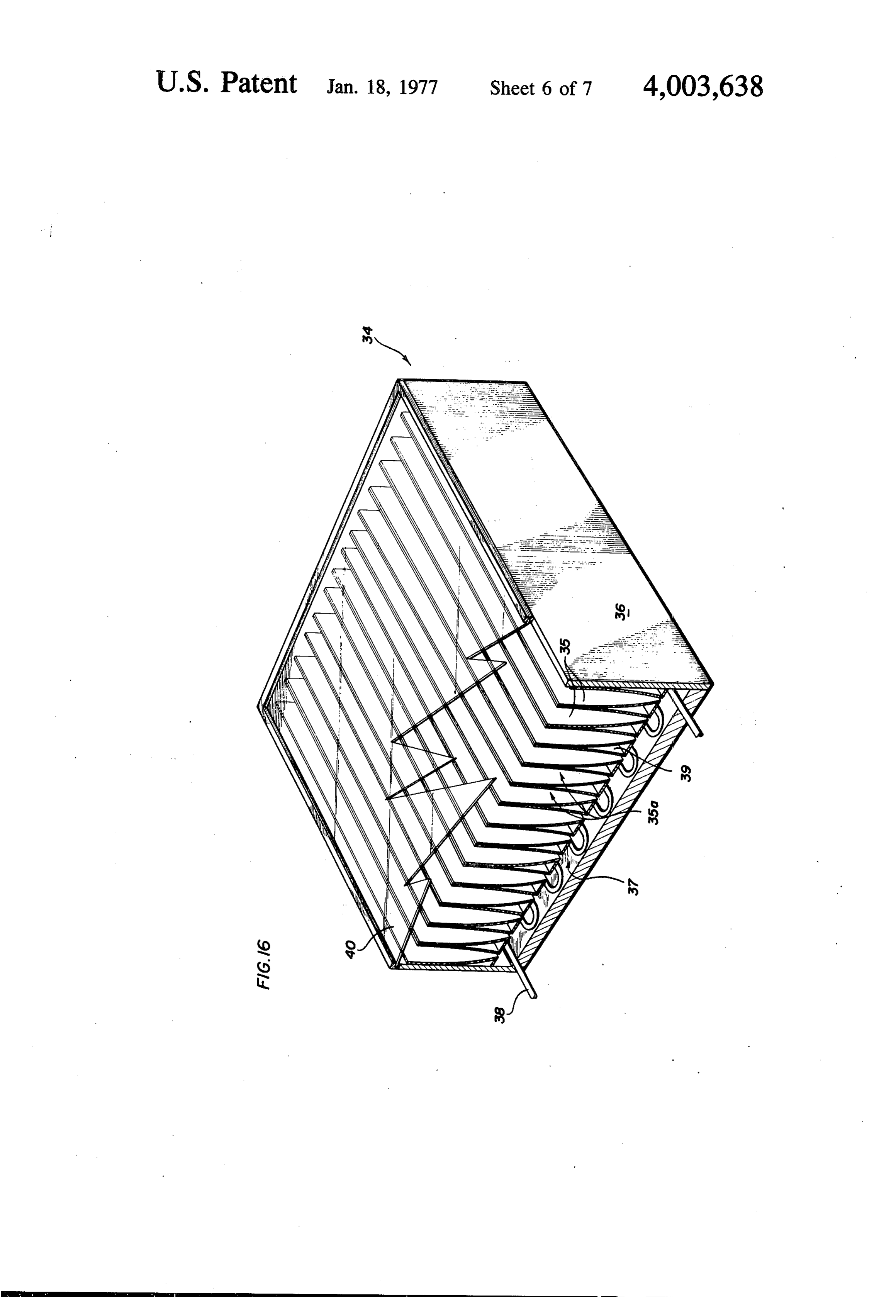
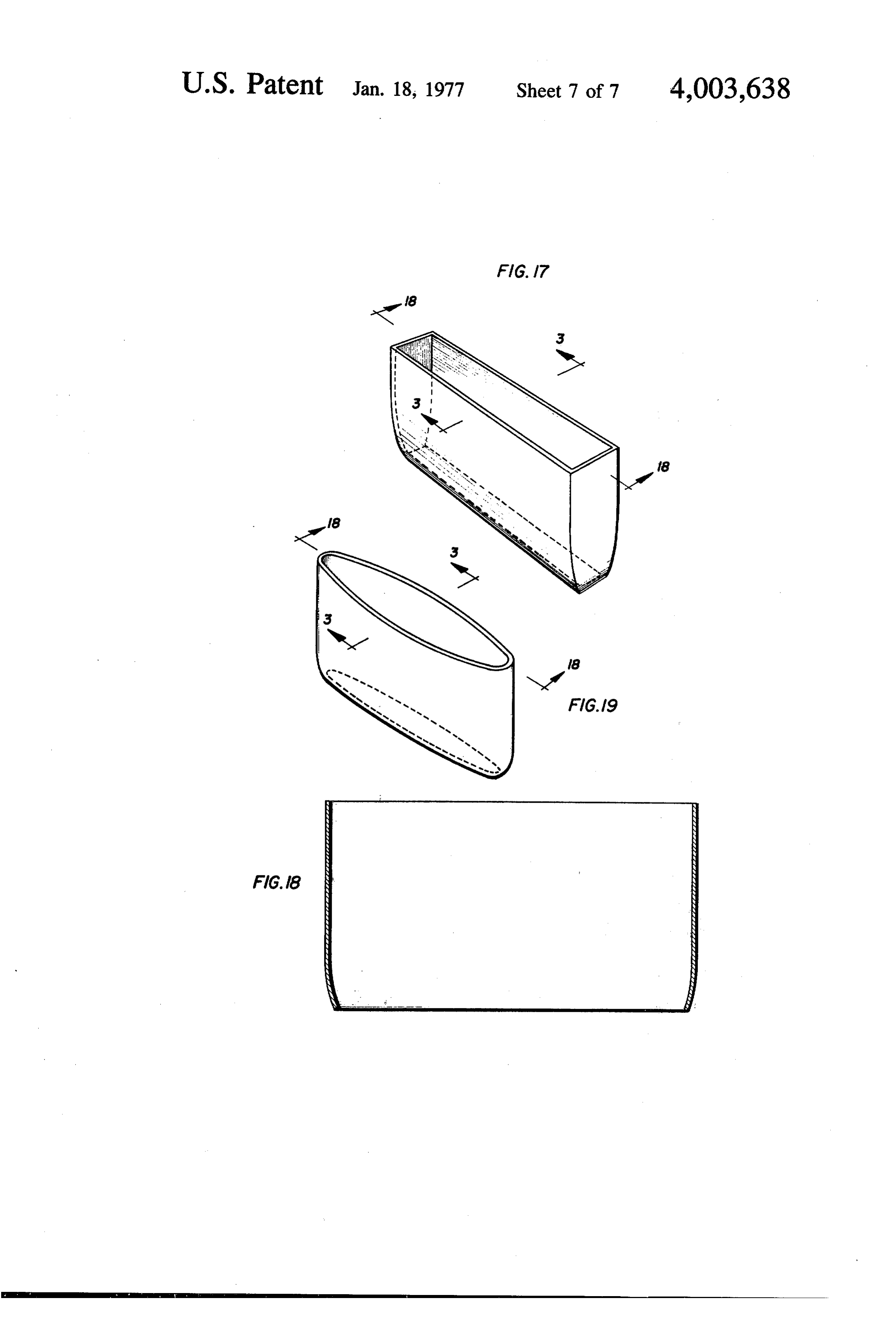
FIG. 10 is a sectional view taken along line 10-0 of ing laterally corresponding edges of exit and entrance FIG. 9. apertures) falling within the shaded area of FIG. 5. It FIG. 11 is a schematic view of an embodiment of the may be noted that the shaded area has as its boundary invention useful in solar energy collection. but does not include a straight line as illustrated in the FIG. 12 is a graphic representation of relative solar collector of FIG. 4. An included parabolic line as motions. shown in the embodiment of FIG. 3 forms the other FIG. 13 is a variant form of FIG. 12. boundary and is described in greater detail hereafter. FIG. 14 is a graphic representation of the acceptance Concave curving lines of length greater than that of the of a collector of the invention in terms of optical direc above-mentioned parabolic line are also contemplated. tion cosines. 10 The profile curve of a much preferred embodiment FIG. 15 is a graphic representation of relative solar of a collector of the invention is shown in FIG. 3. The motion compared to the field of acceptance of a collec following aspects of that embodiment are of particular tion trough of the present invention. interest in understanding the invention. FIG. 16 is a schematic view of a solar energy collec 1. The concentrative capability of the collector, i.e., tor of the present invention. 15 the ratio of exit aperture transverse dimension d to FIGS. 17-19 are schematic views of radiant energy entrance aperture transverse dimension d, is equal to collectors of the present invention. the sine of the half field of view (0) of the trough. DETAILED DESCRIPTION 2. The height, L, of the collector is equal to one-half the sum of d and d, multiplied by the cotangent of the
FIG. 1 illustrates an embodiment of an electromag 20 half field of view.
netic energy collector of the present invention includ ing a generally trough-shaped body 10 having longitu of3.a The profile curve of each wall element is a section dinally extending, substantially parallel, geometrically edge of the exithaving parabola as its focus the laterally opposed aperture and as its axis a line forming similar side wall elements 11, 11, the inner surfaces an angle with the optical axis of the trough equal to the 11a, 11a of which are of energy reflective material. As 25 shown, wall elements 11, 11 taper from an entrance half field of view (0) of the trough. aperture 12 to an exit aperture 13. FIG. 2 illustrates a energyThederiving 4. embodiment accepts for concentration all from within an average elliptical coni similar structure including end wall elements 14, 14 cal field of acceptance developed by the geometric which preferably extend from opening 13 to opening accumulation of all elliptical 12 and preferably also have energy reflective inner 30 tance at all points within theconical plane fields of accep of the entrance surfaces 14a, 14a. As discussed in greater detail later, aperture, the parameters of each of said several fields provision of reflective side wall elements results in being as follows (See FIG. 6):
donation of optical properties approximating provision a. The apex of the cone is any point, P, in the plane of a trough of infinite length.
The optical properties of collectors of the type shown 35 b. of The the entrance aperture;
axis of the cone is a line parallel to the optical in FIGS. 1 and 2 are best illustrated through consider axis of the trough;
ation of FIGS. 3, 4 and 5. In FIG.3 a preferred embodi c. The semi-minor axis of the cone is in a direction ment of a collector of the present invention is seen to transverse to the trough and subtends an angle have an entrance aperture of a transverse dimension d, equal to the half field of view (8) of the trough; and an exit aperture of a transverse dimension d, an overall 40 height L, an optical axis designated OA, and a half field d. The semi-major axis extends in the longitudinal of view, designated 6. The optical axis of the trough is direction of the trough and subtends an angle ap defined by a line extending from the entrance aperture proaching 90 (as the trough approaches infinite to the exit aperture, all points of which are equidistant length).
from respective opposed edges of each of said aper 45 It will be noted that since semi-major axis of the field tures. The half field of view of the trough of FIG. 3 is of acceptance at any point, P, approaches 90 for a defined for the purposes of the present invention as the collector of infinite length, and since provision of re angle formed by the intersection of the optical axis and flective end walls donates optical properties approxi a straight line connecting an edge of one aperture with mating provision of an infinitely long trough, a cross the laterally opposed edge of the other. 50 section (taken parallel to the plane of the entrance A property common to all collectors of the invention aperture) of the average field of acceptance of a collec is the collectors "field of acceptance' which is defined tor as in FIG. 2 approximates the shape of an infinitely as that three dimensional field from within which radi long rectangular strip. It follows that the area of a ant energy (rays) impinging upon a given point in the sphere of unit radius intercepted by this field of accep plane of the collector entrance aperture will reach the 55 tance (the solid angle in steradians) approaches four exit aperture either directly or by way of one or more times the half field of view (8), provided the angle 0 is reflections from the collector reflective surfaces. Put measured in radians (one radian being approximately another way, rays generated within the field of accep 57.3°).
tance of a collector and reaching the entrance plane It is especially noteworthy that the field of accep will invariably reach the exit aperture and those rays 60 tance of the embodiment is identical at each and every generated outside the field will not. point, P, in the plane of the entrance aperture. This For the purposes of the present invention, the shape being the case, the field of acceptance is not subject to of a wall element 11 as revealed by the transverse cross failure or diminution at the edges of the collector sectional view of the collector 10 will be known as the trough and the maximum angle of acceptance within "profile curve' of the element. Accordingly, the profile 65 the field of acceptance as measured in a plane trans curve of a side wall element of a collector constructed verse to the collector, i.e., the angular acceptance of according to the present invention may, for example, the entrance aperture, 6n, of the collector is quantita be any substantially smooth, non-convex line (connect tively equal to the angle of the half field of view (8).
Page 11
S 6
Another property of interest in the embodiments of tance at all points in the plane of the entrance aperture FIGS. 1-3 is that radiant energy in the plane transverse would be equal to 6°. In particular, radiant energy im to the trough which impinges at angles less than but pinging upon a point, P1, near the outermost edge of closely approximating 6 with respect to the optic the entrance aperture would reach the exit aperture if axis are transmitted to the exit aperture with one or no 5 it impinged upon Pi from an angle of less than about 6 reflections. in either direction measured transversely to the trough Further illustrative of such a collector's properties is optical axis.
the comparison of its efficiency to that of a perfectly Assume further the construction of a second collec absorbing flat surface for isotropic radiant energy im tor of the form illustrated in transverse section in FIG. pinging on the entrance aperture at all angles up to 90 0 4 having dimensions d, d, and L identical to those first with respect to the optic axis. The ratio of energy per of the collector. The collector would, of course, pro second per unit area accepted by the collector to the vide the same theoretical concentration of isotropically energy per second per unit area accepted by the ab impinging energy but the field from which energy could sorbing surface is equal to the collector's concentrative be gathered would be much less sharply defined. En capability (the ratio of exit aperture width, d, to en 15 ergy impinging upon a point, Pi, near the outermost trance aperture width, d). edge of the entrance aperture would be channeled to In practice, numerous departures from the dimen the exit aperture only if it impinged upon Pi from an sional relationships present in FIGS. 1-3 may be made angle of less than about 1 measured transversely to the in the construction of a collector which will yield satis trough optical axis in one direction or less than about factory, albeit perhaps less than ideal, overall results. 20 11 from the opposite direction. For example, it may be noted that in FIG. 3 side wall 11 Use of straight or substantially straight side wall ele terminates at a point wherein a line tangent to its para ments as in FIG. 4 would give rise to acceptance of bolic curvature would lie parallel to the optical axis. It energy from marginal angles only after multiple reflec may be desirable in some embodiments to provide a tions with consequent energy loss due to absorption by truncated collection trough having a height less than 25 less than ideally reflective surfaces. The above example that of the collector of FIGS. i-3 and in such cases side is schematically illustrated in FIG. 7. : wall would terminate short of the above-mentioned While collection troughs of the invention preferably point. include smoothly curving side walls, it is anticipated it may be expedient to increase the overall height of that some economic advantage in fabrication might be the collector by linearly extending reflective side walls 30 derived through use of walls having one or more seg 11a, 11a beyond the entrance aperture and parallel to ments revealed in profile curve as straight lines. the optic axis. Such virtual extension of the entrance It is contemplated that space limitations may develop aperture away from the exit aperture does not serve to special utility for "half trough' structures as illustrated alter the angular acceptance of the collector but may in a preferred embodiment by FIGS. 9 and 10 wherein diminish the collector's efficiency because of resultant 35 the trough body 15 includes entrance and exit aper multiple reflections. It may further be expedient to tures 16 and 17, respectively, along with inwardly ta provide linear "transition" reflective wall segments pering side wall element 18, a straight wall element 19 extending away from the edges of the exit aperture, and, preferably, end wall elements 20, 20. Inner wall either parallel to the otpic axis or preferably tapering surfaces 18a, 19a and 20a would be radiant energy slightly outwardly, to accomodate transmission of rays 40 reflective. In the embodiment illustrated, dimensional passing through the exit aperture toward a photocell relationships maintained in fabrication are similar to detector or the like. those employed in construction of an embodiment Similarly, it is likely that a collector might be more according to FIG. 1-3, with expected modifications, economically fabricated in the form more closely ap i.e., entrance and exit apertures have one half the trans proximating that illustrated in cross section in FIG. 4. 45 verse dimension, the half angle of view is the same, the As might be predicted from known two dimensional length is the same, the reflective surface 19a of wall analyses of optical collection properties of right circu element 19 lies along what would be the optical axis of lar cones (see, e.g., Williamson, "Cone Channel Con a "full trough', the focus of the parabolic curvature of denser Optics' J. Opt. Soc. Am..., Vol. 42, No. 10, pp. the side wall 18 is at what would be the opposite edge 712-15 (1952) and, White, "Cone Channel Optics' 50 of the exit aperture for a full trough (shown in phantom Infrared Physics, Vol. 5, pp. 179-85 (1965)), a consid lines), the axis of the parabola would form an angle erably more diffusely defined field of acceptance exists with the optic axis equal to the half field of view and for such a structure, owing to the fact that the maxi average field of acceptance would be an elliptical cone mum angle of acceptance for given points in the plane approaching an infinitely long rectangular strip in of the entrance aperture is subject to variance depend 55 transverse cross section for an infinetely long collector. ing upon relative transverse distance from the optical FIG. 8 illustrates in cross section a tandem trough axis of the trough. This fact may be best illustrated collector which, under circumstances hereafter de through consideration of the following hypothetical scribed, may provide greater factors of concentration example. than provided by a single trough. In the embodiment 60 shown, there is a first trough 21 having respective en
EXAMPLE I trance and exit apertures 22 and 23, as well as side wall Assume the construction of a first collector accord elements 24, 24 having energy reflective inner surfaces ing to FIGS. 1-3 wherein the ratio of d to d. (and 24a, 24a. Contiguous to exit aperture 23 is a second hence the concentration factor) is 9.6 and further that trough 25 having an entrance aperture 26 of transverse the half field of view equals approximately 6. The 65 dimension equal to aperture 23 and an exit aperture 27, height (L) of the collector would be a fixed dimension as well as side wall elements 28, 28 having energy re according to the relationship described above, i.e., L = flective inner surfaces 28a, 28a. Trough 21 is filled with % (d. -- d.) cot 6. The maximum angle of accep a medium having a refractive index, n (e.g. air, which
Page 12
has a refractive index of approximately .0), and inches. The concentration provided by trough 21 trough 25 is filled with a material having a refractive would be factor of 3.6 and the concentration of the index, n2, greater than n (e.g., lucite, which has a re entire tandem system would be equal to 1.5 times 3.6, fractive index of approximately 1.5). or 5.4.
in understanding the operation of the embodiment of 5 Finally, it may be noted that approximately the same FIG. 8, it should be noted that an energy concentrator concentration may be derived through use of a single of the type of collector FIGS. 1-3 functions in part to collector in optical contact with air (n approximately reflect energy from within the collector's field of ac equal to 1) at the entrance, but filled with a medium of ceptance to the exit aperture. In practice, some energy n is 1.5 and having 6m equal to 10.6 and other di will directly reach the exit aperture at an angle parallel O mensions according to the relationships above de to the optic axis of the collector while, at the opposite scribed.
extreme, some energy will reach the plane of the exit According to another aspect of the invention, there aperture at a grazing angle of nearly 90'. To further are proposed systems for collection of solar energy concentrate such grazing energy toward a tandem sec which include radiant energy collector-concentrators ond collector exit aperture requires both the refractive 15 as above described. The inherent attractiveness of di capacity of a medium of greater index of refraction rectly using solar light to meet man's energy needs has than that filling the first collector and an angular field motivated an intense search for practical solar power of acceptance for the second collector equal to the schemes. For most of these, it is necessary to concen critical angle of its medium. With this in mind, the trate the sun light by at least an order of magnitude in operation of a tandem collector will be best understood 20 order to achieve high temperatures. This poses no through consideration of the following hypothetical problem in principle because the rays of sunlight are example. quite parallel (the half-angle 6 subtended by the solar EXAMPLE II disk is only s4) provided one tracks the sun's loca tion in the sky with an accuracy comparable to 6.
Assume one wished to concentrate radiant energy to 25 Because of the formidable technical problems asso the longitudinally-extending photoelectric surface of ciated with tracking to this precision, it would clearly an instrument having a transverse dimension da, equal be an enormous advantage if the required concentra to 1 inch. Assume further that one wished to concen tion was achievable by a relatively stationary collector, trate energy from an angular field of acceptance of half i.e., one requiring little or no diurnal movement. This angle equal to 16. To accomplish such a result one 30 possibility was, in fact, explored in Tabor, infra, and the might construct a single trough collector as shown in disappointing conclusion was reached that the maxi FIGS. 1-3 filled with a medium having an index of mum possible concentration obtainable by a stationary refraction of 1. Since the exit aperture dimension is 1 collector was 3 or 4. This result has been generally inch and the desired maximum angle of acceptance is accepted to the present time. However, Tabor's analy 16, the entrance aperture transverse dimension and 35 sis was based on conventional imaging optics and pre overall height of the trough may be derived from the dated the inventor's more recent developments which relationships heretofore described i.e., the ratio of showed that systems that collect light but do not image transverse exit aperture dimension to entrance aper can achieve a greater concentration than imaging sys ture dimension equals the sine of the half field of view terms.
(which for the collector of FIGS. 1-3 equals the maxi 40 Inasmuch as it is desired to concentrate solar radia mum angle of acceptance), and, the overall height of tion with ground based collectors, it is convenient for the collector equals half the sum of the entrance and the purposes of discussing solar tracking problems to exit aperture transverse dimensions multiplied by the adopt a 'Ptolemaic' description of the sun's motion in cotangent of the half field of view. The transverse di- ' the sky. To an adequate approximation, the apparent mension of the entrance aperture would thus equal 3.6 45 motion of the sun as viewed from a fixed point on earth, inches. The concentration factor of the collector would describes the cone depicted in FIG. 12. In this figure be equal to 3.6. the X axis direction is along north, the Y axis direction One might instead construct a tandem trough collec along west and Z axis direction along the vertical. The tor as in FIG. 8 wherein the first trough 21 was filled cone axis is in the X, Z plane, inclined at angle X, which with a medium having an index of refraction, n, of 1, 50 is the latitude. The cone opening angle, o, is the angle the second trough 26 was filled with a second medium between the earth's axis of rotation and the earth-sun having an index of refraction, n, of 1.5 and the photoe direction. Since the earth's axis is inclined at an angle lectric surface was in optical contact with the second of approximately 23.5 with respect to the normal to medium. The maximum angle of acceptance (critical the plane of its orbit (the ecliptic plane), the angle angle) for trough 25 would be equal to the inverse sine 55 varies between the approximate limits 66.5 s or s of the index of refraction of the medium filling trough 1 13.5 during the course of a year. Except at a time of 21 divided by the index of refraction of the medium equinox, when a F 90° and the apparent solar path filling trough 26, i.e. 6m - arc sine n1/n F arc sine describes a great circle wherein the sun does not “rise' 1/1.5 = arc sine 0.6666 = 42. Given dimension d of or "fall' in the vertical, the problem of collecting solar exit aperture 27 equal to 1 inch and maximum angle of 60 light is non-trivial and becomes most demanding at acceptance equal to 42, d, the transverse dimension solstice (cy in 90 it 23.5'). Collection and concentra of the entrance aperture 26 would be equal to 1.5 tion of solar light by high factors at the time of solstice inches and the overall height would be 1.4 inches. With for a reasonable fraction of the day, say 6 to 8 hours, respect to trough 21, since the exit aperture 23 trans may be considered the fundamental problem of solar verse dimension is equal to 1.5 inches and the desired 65 collection. This is so because at such times the appar maximum angle of acceptance is equal to 16, the ent rise or fall in the vertical requires following or transverse dimension, d, of the entrance aperture 22 tracking the solar disk "upwardly' about 12 within the would be 5.4 inches and the overall height would be 12 3 or 4 hours prior to its reaching the zenith (noon)
Page 13
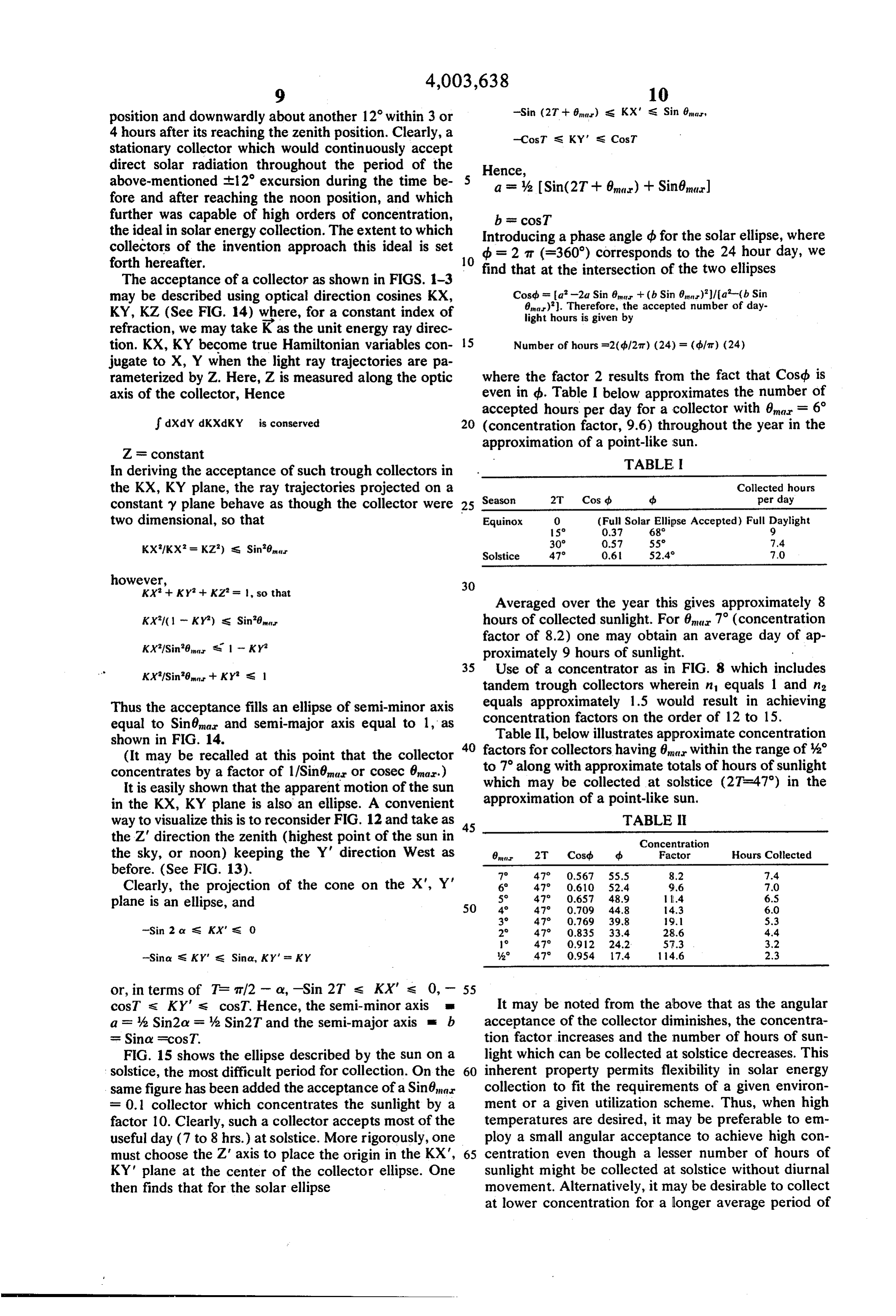
position and downwardly about another 12 within 3 or -Sin (27 - 8) s KX' s Sin 6, 4 hours after its reaching the zenith position. Clearly, a -CosT S KY' s CosT stationary collector which would continuously accept direct solar radiation throughout the period of the above-mentioned th2 excursion during the time be 5 Hence, a = % Sin(2T - 6) - Sin6m) fore and after reaching the noon position, and which further was capable of high orders of concentration, b = cosT the ideal in solar energy collection. The extent to which Introducing a phase angle ds for the solar ellipse, where collectors of the invention approach this ideal is set db = 2 m (=360') corresponds to the 24 hour day, we forth hereafter. 10 find that at the intersection of the two ellipses The acceptance of a collector as shown in FIGS. 1-3 may be described using optical direction cosines KX, Cosdb = a -2a Sin 8 + (b. Sin 0)/a'-(b. Sin 8)). Therefore, the accepted number of day
KY, KZ (See FIG. 14) where, for a constant index of refraction, we may take K as the unit energy ray direc light hours is given by tion. KX, KY become true Hamiltonian variables con 15 Number of hours =2(d.127t) (24) = (dfat) (24) jugate to X, Y when the light ray trajectories are pa rameterized by Z. Here, Z is measured along the optic where the factor 2 results from the fact that Cosqb is axis of the collector, Hence even in b. Table I below approximates the number of accepted hours per day for a collector with 6 = 6 dXdY dKXd KY is conserved 20 (concentration factor, 9.6) throughout the year in the approximation of a point-like sun.
ZF constant
In deriving the acceptance of such trough collectors in TABLE I the KX, KY plane, the ray trajectories projected on a Season 2T Cos (b. d Collected hours per day constant y plane behave as though the collector were 25 two dimensional, so that Equinox
O (Full Solar Ellipse Accepted) Full Daylight
Solstice 470 0.61 52.4 7.0
however, 30
Averaged over the year this gives approximately 8
KX/(1 - KY) S. Sin'8 hours of collected sunlight. For 6m 7 (concentration factor of 8.2) one may obtain an average day of ap
KX/Sin'8 s 1 - KY proximately 9 hours of sunlight.
35 Use of a concentrator as in FIG. 8 which includes tandem trough collectors wherein n equals 1 and in
Thus the acceptance fills an ellipse of semi-minor axis equals approximately 1.5 would result in achieving equal to Sinémar and semi-major axis equal to 1, as concentration factors on the order of 12 to 15. shown in FIG. 14. Table II, below illustrates approximate concentration (It may be recalled at this point that the collector 40 factors
for collectors having 6 within the range of 3 along with approximate totals of hours of sunlight concentrates by a factor of 1/Sinéma or cosec 6ma.)
It is easily shown that the apparent motion of the sun which may be collected at solstice (2T=47) in the in the KX, KY plane is also an ellipse. A convenient approximation of a point-like sun.
way to visualize this is to reconsider FIG. 12 and take as 45 TABLE the Z direction the zenith (highest point of the sun in Concentration the sky, or noon) keeping the Y' direction West as 8war 2T Cosd, d Factor Hours Collected before. (See FIG. 13). 70 47° 0.567 55.5 8.2 7.4 Clearly, the projection of the cone on the X', Y' 6 47 0.610 52.4 9.6 7.0
-Sin 2 or S. KX's 0 29 47 0.835 33.4 28.6 4.4
-Sina s KY' s Sina, KY' = KY A. 47 0.954 17.4 14.6 2.3
cosT s KY's cosT. Hence, the semi-minor axis It may be noted from the above that as the angular a = % Sin2a = % Sin2T and the semi-major axis E b acceptance of the collector diminishes, the concentra st Sinov scos T. tion factor increases and the number of hours of sun FIG. 15 shows the ellipse described by the sun on a light which can be collected at solstice decreases. This solstice, the most difficult period for collection. On the 60 inherent property permits flexibility in solar energy same figure has been added the acceptance of a Sinéma collection to fit the requirements of a given environ F 0.1 collector which concentrates the sunlight by a ment or a given utilization scheme. Thus, when high factor 10. Clearly, such a collector accepts most of the temperatures are desired, it may be preferable to em useful day (7 to 8 hrs.) at solstice. More rigorously, one ploy a small angular acceptance to achieve high con must choose the Z axis to place the origin in the KX', 65 centration even though a lesser number of hours of KY' plane at the center of the collector ellipse. One sunlight might be collected at solstice without diurnal then finds that for the solar ellipse movement. Alternatively, it may be desirable to collect at lower concentration for a longer average period of
Page 14
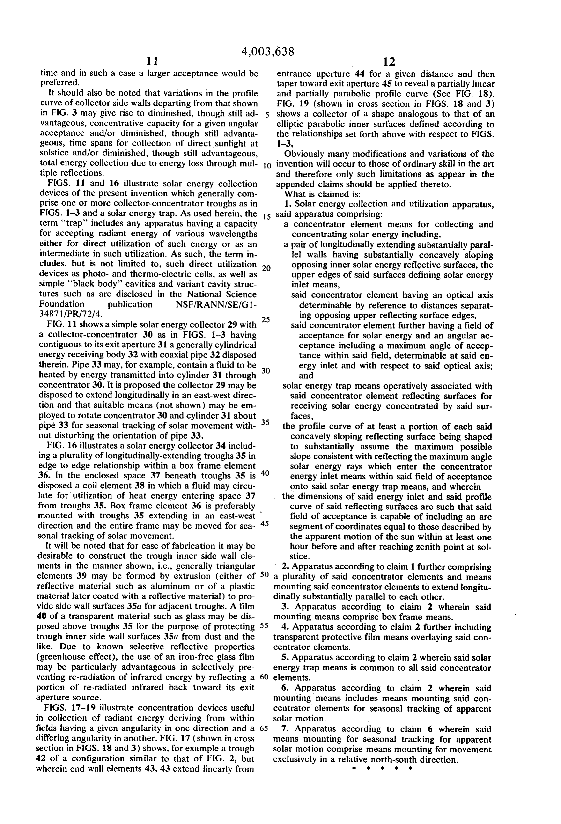
time and in such a case a larger acceptance would be entrance aperture 44 for a given distance and then preferred. taper toward exit aperture 45 to reveal a partially linear It should also be noted that variations in the profile and partially parabolic profile curve (See FIG. 18). curve of collector side walls departing from that shown FIG. 19 (shown in cross section in FIGS. 18 and 3) in FIG.3 may give rise to diminished, though still ad 5 shows a collector of a shape analogous to that of an vantageous, concentrative capacity for a given angular elliptic parabolic inner surfaces defined according to acceptance and/or diminished, though still advanta the relationships set forth above with respect to FIGS. geous, time spans for collection of direct sunlight at 1-3.
solstice and/or diminished, though still advantageous, Obviously many modifications and variations of the total energy collection due to energy loss through mul 0. invention will occur to those of ordinary skill in the art tiple reflections. and therefore only such limitations as appear in the FIGS. 11 and 16 illustratic solar energy collection appended claims should be applied thereto. deviccs of the present invention which generally com What is claimed is:
prise one or more collector-concentrator troughs as in 1. Solar energy collection and utilization apparatus, FIGS. 1-3 and a solar energy trap. As used herein, the 5 said apparatus comprising:
term "trap' includes any apparatus having a capacity a concentrator element means for collecting and for accepting radiant energy of various wavelengths concentrating solar energy including, either for direct utilization of such energy or as an a pair of longitudinally extending substantially paral intermediate in such utilization. As such, the term in lel walls having substantially concavely sloping cludes, but is not limited to, such direct utilization 20 opposing inner solar energy reflective surfaces, the devices as photo- and thermo-electric cells, as well as upper edges of said surfaces defining solar energy simple "black body' cavities and variant cavity struc inlet means, tures such as are disclosed in the National Science said concentrator element having an optical axis Foundation publication NSF/RANN/SE/G1 determinable by reference to distances separat 34871/PR/72/4. ing opposing upper reflecting surface edges, FIG. 11 shows a simple solar energy collector 29 with 25 said concentrator element further having a field of a collector-concentrator 30 as in FIGS. 1-3 having acceptance for solar energy and an angular ac contiguous to its exit aperture 31 a generally cylindrical ceptance including a maximum angle of accep energy receiving body 32 with coaxial pipe 32 disposed tance within said field, determinable at said en therein. Pipe 33 may, for example, contain a fluid to be 30 ergy inlet and with respect to said optical axis; heated by energy transmitted into cylinder 31 through and concentrator 30. It is proposed the collector 29 may be solar energy trap means operatively associated with disposed to extend longitudinally in an east-west direc said concentrator element reflecting surfaces for tion and that suitable means (not shown) may be em receiving solar energy concentrated by said sur ployed to rotate concentrator 30 and cylinder 31 about 35 faces, pipe 33 for seasonal tracking of solar movement with the profile curve of at least a portion of each said out disturbing the orientation of pipe 33. concavely sloping reflecting surface being shaped FIG. 16 illustrates a solar energy collector 34 includ to substantially assume the maximum possible ing a plurality of longitudinally-extending troughs 35 in slope consistent with reflecting the maximum angle edge to edge relationship within a box frame element solar energy rays which enter the concentrator 36. In the enclosed space 37 beneath troughs 35 is 40 energy inlet means within said field of acceptance disposed a coil element 38 in which a fluid may circu onto said solar energy trap means, and wherein late for utilization of heat energy entering space 37 the dimensions of said energy inlet and said profile from troughs 35. Box frame element 36 is preferably curve of said reflecting surfaces are such that said mounted with troughs 35 extending in an east-west 45 field of acceptance is capable of including an arc direction and the entire frame may be moved for sea segment of coordinates equal to those described by sonal tracking of solar movement. the apparent motion of the sun within at least one It will be noted that for ease of fabrication it may be hour before and after reaching zenith point at sol desirable to construct the trough inner side wall ele stice.
ments in the manner shown, i.e., generally triangular 2. Apparatus according to claim 1 further comprising elements 39 may be formed by extrusion (either of 50 a plurality of said concentrator elements and means reflective material such as aluminum or of a plastic mounting said concentrator elements to extend longitu material later coated with a reflective material) to pro dinally substantially parallel to each other. vide side wall surfaces 35a for adjacent troughs. A film 3. Apparatus according to claim 2 wherein said 40 of a transparent material such as glass may be dis mounting means comprise box frame means. posed above troughs 35 for the purpose of protecting 55 4. Apparatus according to claim 2 further including trough inner side wall surfaces 35a from dust and the transparent protective film means overlaying said con like. Due to known selective reflective properties centrator elements.
(greenhouse effect), the use of an iron-free glass film 5. Apparatus according to claim 2 wherein said solar may be particularly advantageous in selectively pre energy trap means is common to all said concentrator venting re-radiation of infrared energy by reflecting a 60 elements.
portion of re-radiated infrared back toward its exit 6. Apparatus according to claim 2 wherein said aperture source. mounting means includes means mounting said con FIGS. 17-19 illustrate concentration devices useful centrator elements for seasonal tracking of apparent in collection of radiant energy deriving from within solar motion.
fields having a given angularity in one direction and a 65 7. Apparatus according to claim 6 wherein said differing angularity in another. FIG. 17 (shown in cross means mounting for seasonal tracking for apparent section in FIGS. 18 and 3) shows, for example a trough solar motion comprise means mounting for movement 42 of a configuration similar to that of FIG. 2, but exclusively in a relative north-south direction. wherein end wall elements 43, 43 extend linearly from xk k k k k
Page 15
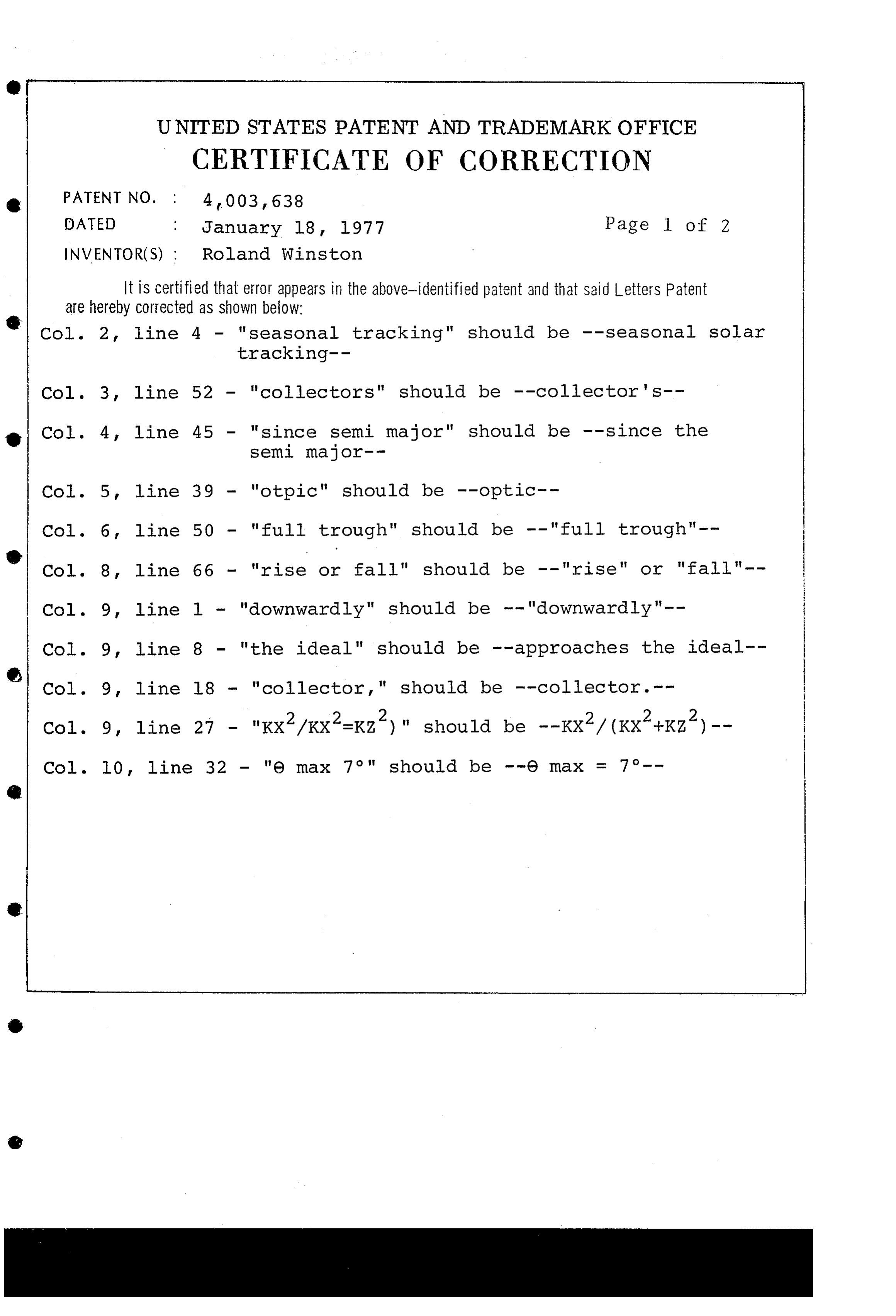
UNITED STATES PATENT AND TRADEMARK OFFICE
CERTIFICATE OF CORRECTION
DATED January 18, 1977 Page 1 of 2 INVENTOR(S) : Roland Winston
It is Certified that error appears in the above-identified patent and that said Letters Patent are hereby corrected as shown below:
Col. 2, line 4 - "seasonal tracking" should be -- seasonal Solar
Col. 3, line 52 - "collectors" should be --collector's-- Col. 4, line 45 - "since semi major" should be -- Since the semi major--
Col. 5, line 39 - "otpic" should be --optic.--
Col. 6, line 50 - "full trough" should be -- "full trough".-- Col. 8, line 66 - "rise or fall" should be -- "rise" or "fall"-- Col. 9, line 1 - "downwardly" should be -- "downwardly".-- Col. 9, line 8 - "the ideal" should be --approaches the ideal-- Col. 9, line 18 - "collector," should be --collector. -- Col. 9, line 27 - "Kx2/Kx2=Kz')" should be --Kx?/ (KX 2 +Kz')--
Page 16
UNITED STATES PATENT OFFICE
CERTIFICATE OF CORRECTION
Patent No. 4,003, 638 Dated January 18, 1977
It is certified that error appears in the above-identified patent and that said Letters Patent are hereby corrected as shown below:
Column 12, line 6 - 'elliptic parabolic inner surfaces' should be - - elliptic paraboloid but including parabolic inner Surfaces -- .
eigned and sealed this
Thirty-first Day of May 1977
At testing Officer Commissioner of Patents and Traulemarks
Provenance
- Collection
- Cited prior art
- Original PDF
- patentimages.storage.googleapis.com →
- Filed
- 1975-09-15
- Pages
- 16
- Method
- pdftotext (the PDF's own text layer) + pdftoppm 300dpi page scans
- Source
- Google Patents bibliographic record
- Granted
- 1977-01-18
- Inventors
- Roland Winston; University of Chicago
- Transcribed from
- patentimages.storage.googleapis.com →