patent · US4481414
Light collection apparatus for a scanner
6 November 1984
Page 1 — bibliographic record
United States Patent (19) 11 Patent Number: 4,481,414 Gasper (45. Date of Patent: Nov. 6, 1984 (54) LIGHT COLLECTION APPARATUS FOR A Colour Television Cameras," Philips Technical Review, SCANNER vol. 24, 1962/63, No. 9, pp. 263-271, Aug. 1963. 75) Inventor: John Gasper, Hilton, N.Y. S. E. Glazer, "Taper Measurement Techniques," Proc. of the Soc. of Photo-Optical Instrumentation Engineers, 73) Assignee: Eastman Kodak Company, vol. 31, 1972, pp. 13-22. Rochester, N.Y. R. I. Seddon, "Interference Filters for Colorimetric (21) Appl. No.: 348,373 Applications," Proc. of the Soc. of Photo-Optical Engi
(22) Filed: Feb. 12, 1982 P. M. van Alphen, "Applications of the Interference of 51 Int. C. ................................................ G01J 3/34 Light in Thin Films," Philips Technical Review, vol. 19, 52 U.S. C. .................................... 250/226; 350/171; 1957/58, No. 2, pp. 59-67. 356/444 H. van Ginkel, "Flying-Spot Scanners for 58 Field of Search ................ 356/443, 444; 250/226, Colour-Television," Philips Technical Review, vol. 21, 250/227, 228, 216,566,568, 569,570; 350/171, 1959/60, No. 8, pp. 234-250.
173, 96.28 Primary Examiner-David C. Nelms (56) References Cited Attorney, Agent, or Firm-David M. Woods
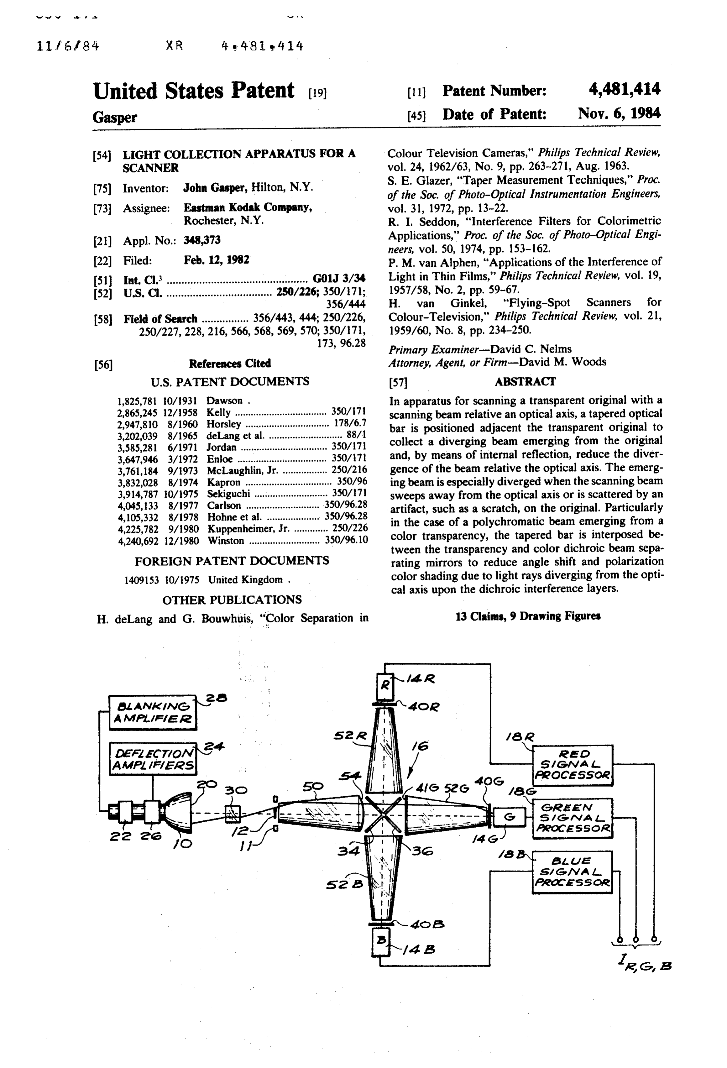
1,825,781 10/1931. Dawson . In apparatus for scanning a transparent original with a 2,865,245 12/1958 Kelly ................................... 350/71 scanning beam relative an optical axis, a tapered optical 2,947,810 8/1960 Horsley ................................ 178/6.7 bar is positioned adjacent the transparent original to 3,202,039 8/1965 deLang et al. ............................ 88/1 collect a diverging beam emerging from the original 3,585,281 6/1971 Jordan ................................. 350/17 3,647,946 3/1972 Enloe ... ... 350/171. and, by means of internal reflection, reduce the diver 3,761,184 9/1973 McLaughlin, ... 250/216 gence of the beam relative the optical axis. The emerg 3,832,028 8/1974 Kapron ................................. 350/96 ing beam is especially diverged when the scanning beam 3,914,787 10/1975 Sekiguchi............................ 350/71 sweeps away from the optical axis or is scattered by an 4,045, 33 8/1977 Carlson ........ ... 350/96.28 artifact, such as a scratch, on the original. Particularly 4,105,332 8/1978 Hohne et al. ............ ... 350/96.28 in the case of a polychromatic beam emerging from a 4,225,782 9/1980 Kuppenheimer, Jr.............. 250/226 color transparency, the tapered bar is interposed be 4,240,692 12/1980 Winston ........................... 350/96.10 tween the transparency and color dichroic beam sepa
FOREIGN PATENT DOCUMENTS rating mirrors to reduce angle shift and polarization 1409153 10/1975 United Kingdom. color shading due to light rays diverging from the opti cal axis upon the dichroic interference layers.
OTHER PUBLICATIONS
H. deLang and G. Bouwhuis, "Color Separation in 13 Claims, 9 Drawing Figures
efo
AOCASSOe
Casem
SMG Ma L
AeoCAssoa.
Asa Ava
Acolaassoye
Page 2
Drawing sheet — no readable text.
Page 3
Drawing sheet — no readable text.
Page 4
Drawing sheet — no readable text.
Page 5
Drawing sheet — no readable text.
Page 6
Drawing sheet — no readable text.
Page 7
of laser beam illuminating the reconnaissance system.
LIGHT COLLECTION APPARATUS FOR A Optical arrangements have been suggested for accept SCANNER ing a wide field of rays and reducing their impingement
BACKGROUND OF THE INVENTION
angle upon the interference filter (see, for example, the 5 combination of a hyperhemispherical lens and a fresnel 1. Field of the Invention lens described in U.S. Pat. No. 3,761,184 or the optical The invention generally relates to optical scanning cone-like condenser described in U.S. Pat. No. apparatus for collecting the light rays of a scanning 4,225,782).
beam emerging from a scanned transparency. More O In view of these well known problems with interfer specifically the invention relates to apparatus for col ence layers, a number of optical designs have been pro lecting and separating a polychromatic scanning beam posed to control polarization and angle shift character into a plurality of separate beams composed of different istics in color scanners. For example, in using a flying wavelengths and, especially, to such optical apparatus spot scanner to form a raster scan upon a transparency, having means for suppressing the effect of scratches in 15 at least one condenser lens is usually inserted in the the transparency. optical path to refract the beams emanating from points 2. Description Relative to the Prior Art outside the middle of the raster towards the axis of the In color-separating apparatus for optically separating system. This is done in such a way that the axes of most a beam of polychromatic light, the beam is ordinarily beams reach the dichroic mirrors at a similar angle split into several components-red, green and blue irrespective that are directed toward separate photosensitive targets, van Ginkel, of 20 their point of origin on the raster (see H.
"Flying-Spot Scanners for Colour Televi
This is conventionally done by passing the beam sion' Philips Technical Review, through two or more partially reflecting mirrors (often 234-250). Another optical design vol. 21, 1959/60, pp. is based on the Philips referred to as dichroic mirrors) having optical interfer color-separating prism system described in the above ence layers with color-selective reflecting and transmit ting properties. However, the band of wavelengths 25 cited de Lang and Bouwhuis article in the Philips Tech reflected by an interference layer is strongly dependent nical Review. This prism system utilizes a compact com on the effective optical path taken by a ray through the bination of interference layers cemented between faces layer as determined mainly by the angle of incidence of of prisms and small air gaps between selected sets of the impinging beam relative to the normal. Where two prisms. The Philips optical geometry in combination or more interference layers are applied to a mirror, as is 30 with glass prisms allows the angles of incidence to be frequently the case, the selective reflection effect is reduced over what can be obtained with conventional further affected by incident angle-shift as the path open air plate type color separation systems. length is changed in varying degrees in the different However neither the condenser lens nor the prism layers. In either case, as the incident angle increases system are sufficiently effective regarding widely di further from the normal, the spectral cut of the dichroic 35 verging rays. Particularly in the case of a transparency, filter, i.e., as exemplified by the reflection curve, shifts light-scattering artifacts (such as scratches, dust parti toward progressively smaller wavelengths. cles, and the like) are common sources of widely di In addition, with an increasing angle of incidence, an verging rays. A typical artifact is a scratch on the trans undesirable polarization phenomenon occurs due to parency which scatters light from a scanning beam. asymmetry in the response of the electric vector charac Oftentimes, some of the scattered light will be at such terizing the light beam. The electric vector for each an extreme angle that it will not be collected at all by wavetrain in the light beam can be resolved into two components, one perpendicular to the plane of inci the to light collection apparatus. In these cases, the signal the photosensitive targets will be less than that for dence (the perpendicular component) and one lying in areas immediately adjacent to the scratch that contain this plane (the parallel component). With increasing 45 the same scene detail. Where a reproduction is made angle of incidence the coefficient of reflection becomes from such target signals, the scratch will be readily greater for the perpendicular component and smaller visible because of the decreased signal. In the case of for the parallel component, meaning that the perpendic transparency scanners it has been suggested ular component is preferentially reflected. As a result the optical system with reflecting surfacestotosurround redirect the mean reflection caused by both components is col 50 light scattered by scratches back upon the photosensi or-shifted as the angle of incidence is increased. In the tive targets to obscure the effect of scratches in the case of either effective optical path shift or polarization effect, undesirable color shifts occur across the images transparency.
Other less extremely angled rays of scattered light formed upon the photosensitive targets. These problems are discussed in greater detail in several journal articles: 55 may enter the light collection apparatus but still at a P. M. van Alphen, "Applications of the Interference of sharply increased angle of incidence relative to the Light in Thin Films,” Philips Technical Review vol. 19, interference layers. Since the reflection characteristics 59–67, 1957/58; H. de Lang and G. Bouwhuis, "Color of the interference layers are modified by angle-shift Separation in Colour-Television Cameras,” Philips effects, some rays of the scratch-scattered beam are Technical Review vol. 24, 263-271, 1962/63; or R. L. deflected toward incorrect targets. In the case of color Seddon, "Interference Filters for Colorimetric Applica reproductions, the scratch then appears in a different tions,” Optical Coatings, vol. 50, 153-162, 1974. color from the adjacent areas. The reflector-encased Apart from their use in dichroic filters, interference design suggested above does not inherently control layers are used to form filters that provide narrowband angle-shift, therefore leading to the appearance of col radiation detection. As an example, radiation reconnais 65 or-shifted scratches even though proper neutral expo sance systems having a wide field of view include inter sure may be achieved for the area of the reproduction ference filters to provide sharp cut-on or cut-off for corresponding to the scratched area of the transpar narrowband detection, e.g., to detect a particular type ency.
Page 8
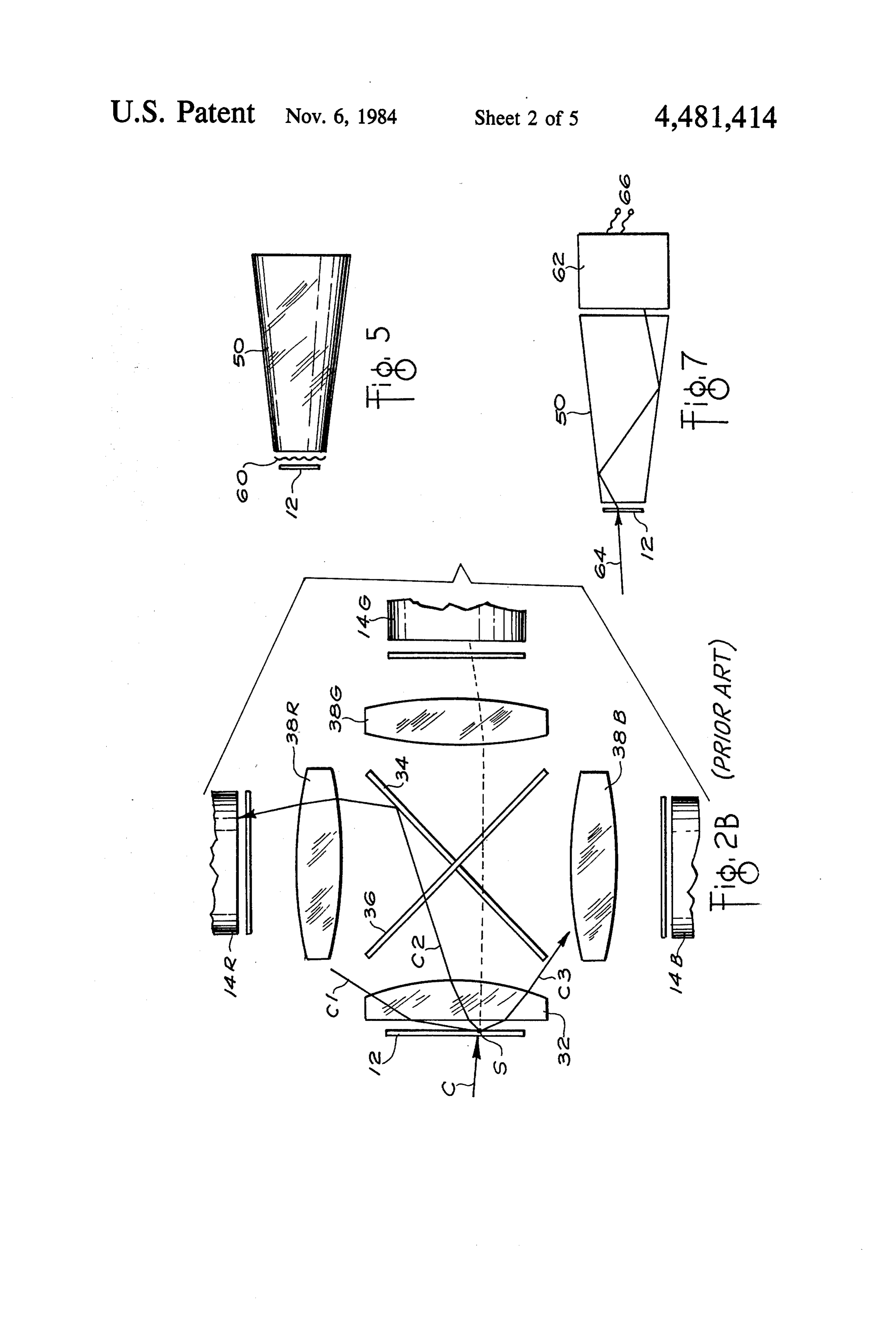
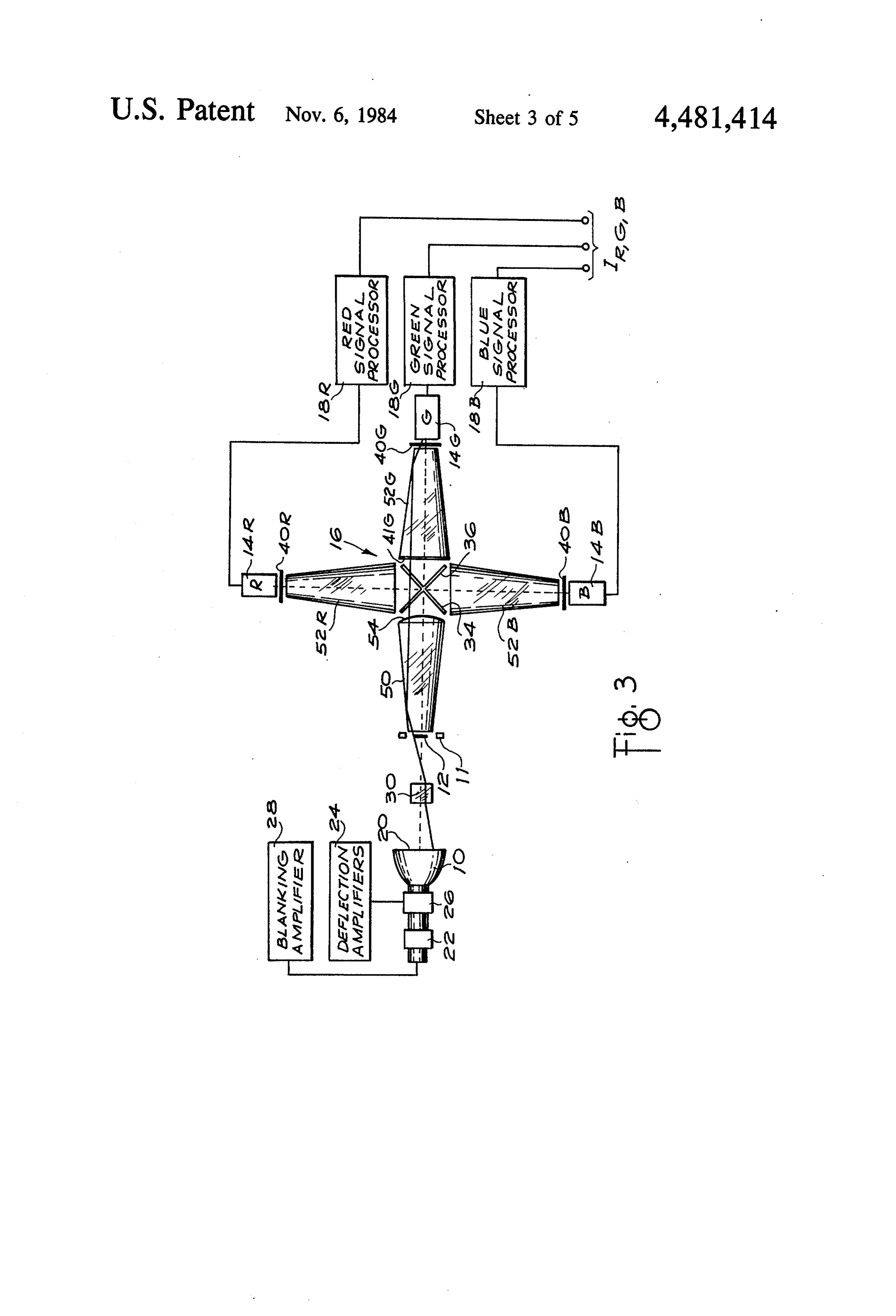
Illumination of the transparency with strongly diffuse FIG. 3 is a block diagram illustrating the optical light transmitted by a diffuser would help to suppress design of a flying spot scanner incorporating a light the effect of scratches in the transparency. However, collecting and color separating apparatus in accordance because it would fail to provide adequate color separa with the invention;
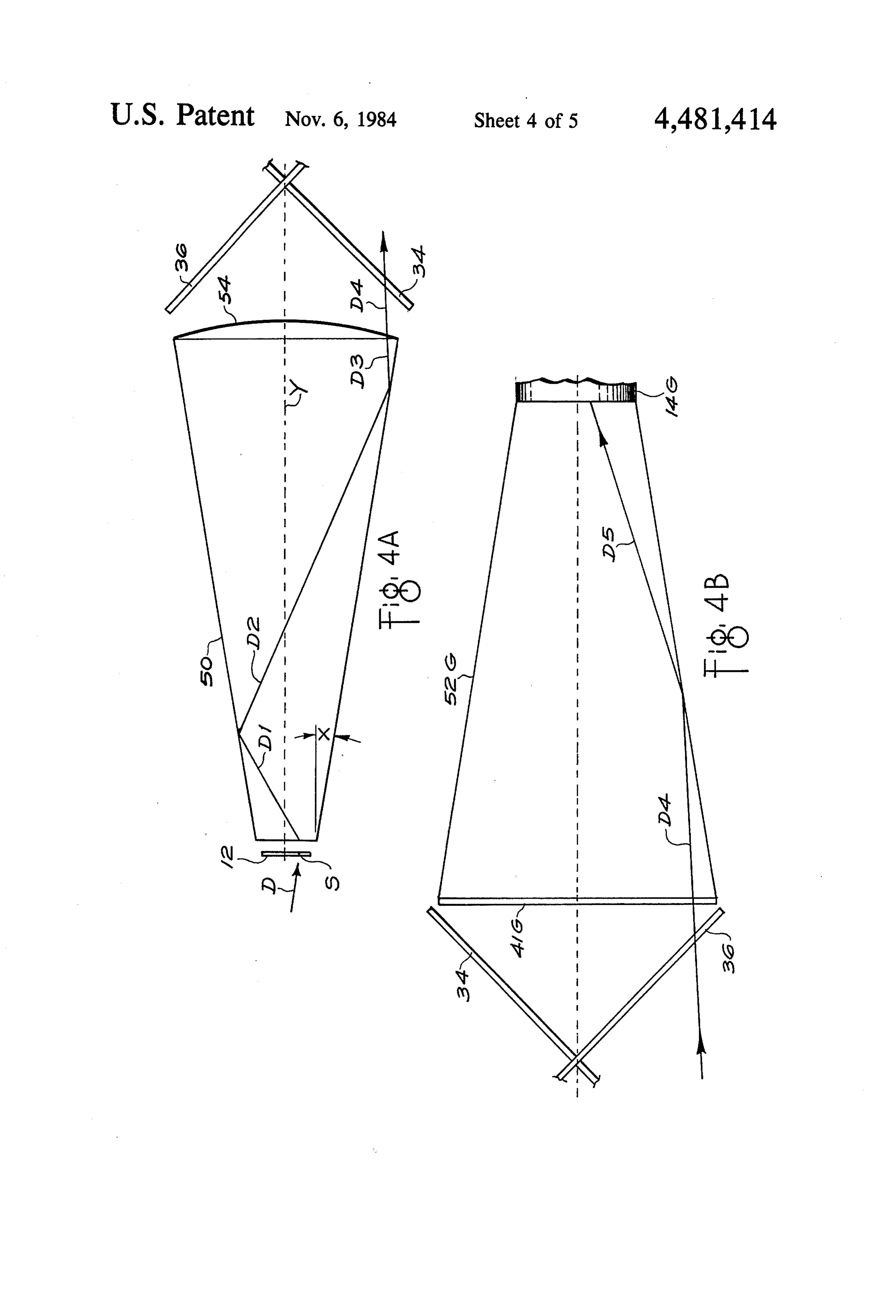
tion and lead to a serious reduction in signal-to-noise 5 FIGS. 4A and 4B are enlarged diagrams of the light ratio for the targets, it is basically impractical where a collecting and color separating apparatus of FIG. 3 specular scanning source is required. Another method showing also a ray diagram of a typical path of a light has been to use a "liquid gate' in which the transpar ray scattered from a scratch on the transparency and ency faces are coated with a liquid layer which O through tapered bars in accordance with the invention; smoothes out the surface and renders dirt and scratches FIG. 5 is a diagram of one of the tapered bars incor much less visible. However, the attendant mechanical porating a high gain light diffusion filter on one end and operational problems of a "liquid gate" limit its thereof;
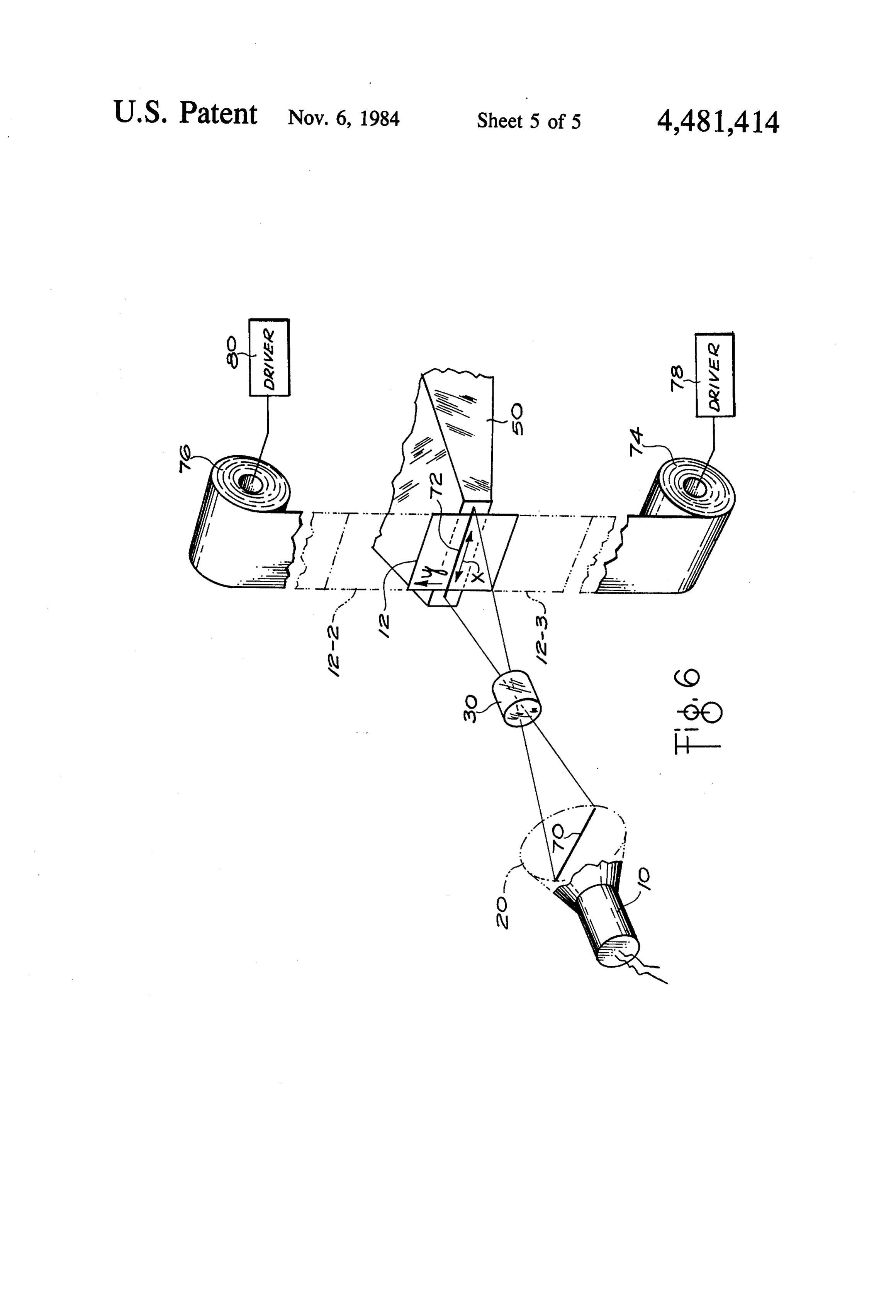
practical applications. In yet another approach, United FIG. 6 is an alternative embodiment of the invention Kingdom Patent Specification No. 1409153 describes 15 useful with apparatus that provides page scan move the procedure of detecting light scattered from blem ment of the transparency; and ishes on cine film in order to electrically substitute a FIG. 7 is a further embodiment of the invention for grey level or adjacent picture signal for the scanning use without a beamsplitter.
signal obtained from the blemished area. Besides the DESCRIPTION OF THE PREFERRED circuit complexity of implementing such a procedure, EMBODIMENT the blemished area is incorrectly reproduced relative its original color and density. ' . Since optical scanners are well known in which trans
SUMMARY OF THE INVENTION
parent material such as slides, negatives or movie film is scanned, the present description will be directed in
In accordance with the invention means are provided particular to elements forming part of, or cooperating for generating a beam for scanning a transparency, more directly with, the present invention. Optical scan which is supported relative an optical axis in the path of ner elements not specifically shown or described herein the scanning beam, whereby the direction of the emerg may be selected from those known in the art. Scanning ing beam varies with respect to the optical axis. Means equipment with such elements includes graphic arts are provided to effect relative movement of the beam 30 scanners, telecine and slide scanning apparatus, as well across at least one dimension of the transparency. An as photographic printers. Since the invention has partic optical element is positioned relative the optical path ular utility with the optical scanning of color transpar adjacent the transparency to collect the light beam encies, the description will be directed to this applica tion. However, the invention may be used with color or emerging from the transparency and transmit at least a black portion of the beam by means of internal reflection 35 and white transparencies, positive or negative within the optical element. Such an optical element may transparencies, or transparencies in separate "still' form be tapered and therefore have large and small apertures or joined together as motion picture film. Moreover, at opposite ends thereof, with its smaller aperture posi apparatus in accordance with the invention is useful tioned near the transparency. . ." wherever it is desirable to reduce the incident angle of The invention has particular utility for collecting a beam of light-whether or not polychromatic-rela light emerging from a scanned area of a transparency tive a receiving surface. Furthermore, the source of the having a light-scattering artifact thereon. The transpar scanning beam is clearly a matter of choice. For illustra ency is supported in the scanning light beam whereby tive purposes only, the invention is described in terms of : the beam emerging from the transparency is scattered a beam generated by a cathode ray tube flying spot by the artifact. The tapered optical element is posi 45 scanner. Other scanning beams generated from, for tioned adjacent the transparency to collect a substantial example, a laser or a solid state light source are suitable portion of the scattered light at its smaller input aper for use with the invention.
ture and substantially reduce the divergence of the Referring to FIG. 1, a conventional flying spot scan scattered beam at the output end of the element. ner is illustrated using a conventional combination of In a preferred embodiment, a color transparency is 50 crossed dichroic beamsplitting mirrors and beam con scanned by a polychromatic beam. Means are provided verging condenser lenses. A uniformly bright scanning for separating the polychromatic beam emerging from raster is produced by exciting phosphors on a cathode the transparency into a plurality of spectral compo ray tube 10. The raster is imaged upon a transparency 12 nents. The tapered optical element is interposed be positioned in a film gate 11 on the optical axis 13 of the tween the transparency and the spectral separating 55 scanner apparatus. (An exemplary transparency for means for reducing the angular divergence of the beam such a system is a photographic film transparency, ei of light passing to the spectral separating means. ther a color negative or positive.) The modulated light emerging from the transparency 12 is directed upon
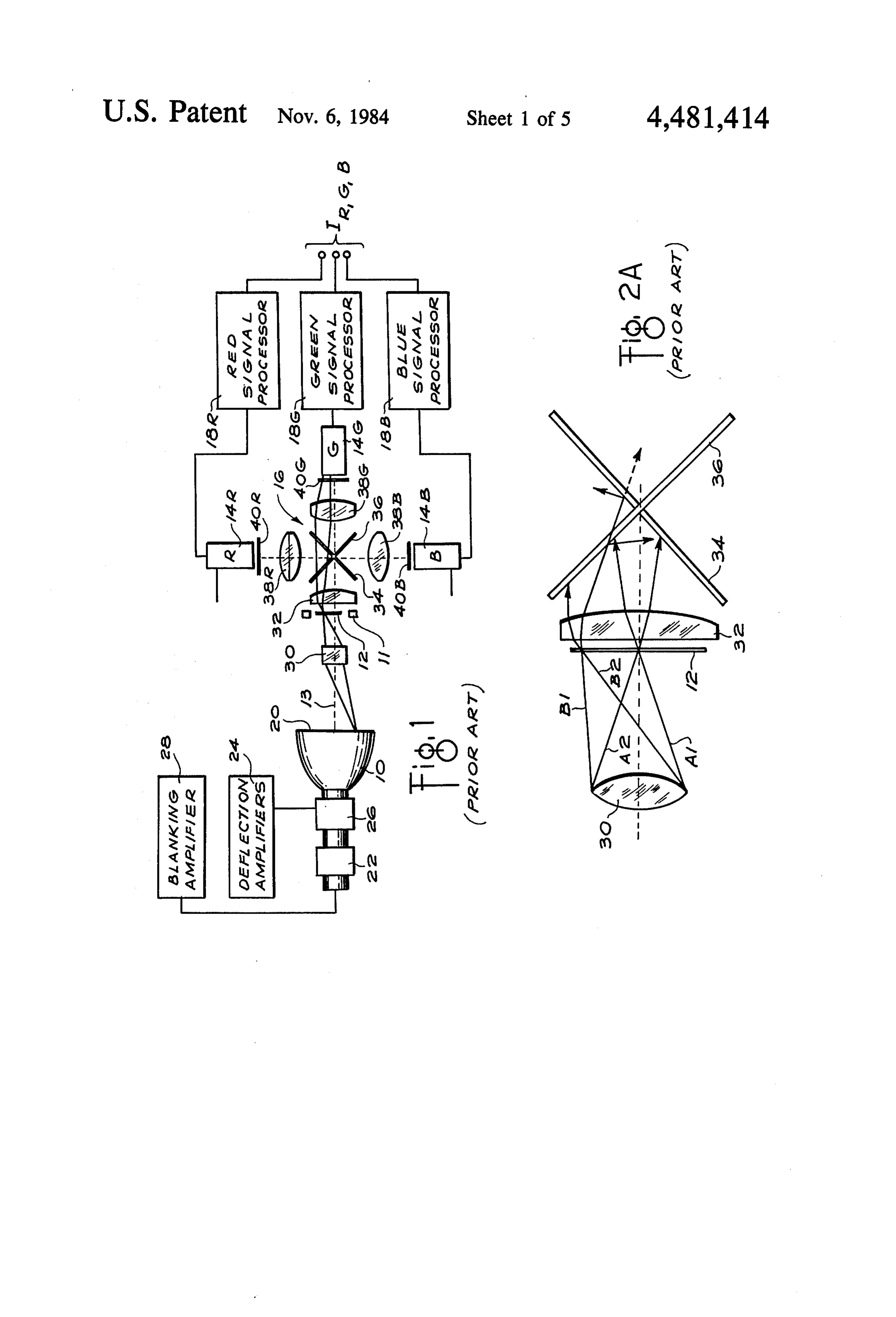
BRIEF DESCRIPTION OF THE DRAWINGS three photoelectric cells 14R, 14G and 14B, for red, A preferred embodiment of the invention will be 60 green and blue light respectively, via beamsplitting described with reference to the drawings, wherein: apparatus generally depicted by the reference character FIG. 1 is a block diagram illustrating the optical 16. The photoelectric cells may be conventional photo design of a flying spot transparency scanner known in cells, phototubes, solid state receptors, or the like. The the prior art; resultant output, after amplification and suitable pro FIGS. 2A and 2B are ray diagrams of typical light 65 cessing in processors 18R, 18G and 18B, constitutes the paths of light beams passing through a transparency image signal I. With this scanning arrangement, illumi without hindrance and scattering from a scratch on a nation of each elementary area of the transparency occurs only at the moment of scanning and for a short transparency, respectively;
Page 9
period immediately afterward during which emission extreme rays of a beam striking the central portion of from the phosphor persists. the transparency 12. Light rays B1 and B2 represent the In order to get a sharply focused spot on the faceplate extreme rays of a beam striking a peripheral portion of of the scanning tube 10, the electron beam generated the transparency 12. Each beam is refracted by the within is converged toward the phosphor screen 20 by condenser lens 32 and directed toward the crossed di a magnetic field generated by a focusing coil 22. THe chroic mirrors 34 and 36. w horizontal and vertical sweeping of the beam is pro Each dichroic filter is designed to provide optimum vided by horizontal and vertical waveforms generated spectral separation of a predetermined narrow-band in deflection amplifiers 24 and applied to a deflection spectral component for a specified incident angle rela coil 26. The electron beam is suppressed during the 10 tive to the normal, i.e., in this case a design angle of 45° flyback period by a blanking amplifier 28. To be satis relative the normal. However, as hereinbefore ex factory for color rendition of a photographic film trans plained, the transmission (and reflection) characteristic parency, a suitably doped phosphor is incorporated into of dichroic filters is strongly affected by incident angle the phosphor screen to generate emissions in the desired shift, i.e., as the incidence angle increases(decreases) portions of the spectrum. While selected for a short 15 relative the normal, the spectral cut of a dichroic filter afterglow, phosphors continue to emit light for some shifts toward progressively smaller(larger) wave time after their excitation thereby affecting the electri lengths. While any angle shift is detrimental, dichroic cal response of the signals obtained from the photocells mirrors arranged at 45° will ordinarily tolerate a small 14R, 14G and 14.B. Suitable equalization is therefore shift before the band edge characteristics change so provided in the processors 18R, 18G and 18B to com 20 substantially as to grossly affect the desired spectral pensate for the effects of phosphor afterglow. separation. For example, if the objective lens 30 oper A conical scanning beam is formed by an objective ates at F/4 the rays A1 and A2 will converge toward lens 30 from the scanning spot of light on the faceplate the transparency 12 at +7°. Although the transmission 20 of the scanning tube 10. The scanning beam is imaged passband of the mirror 36 and the mirror 34 will be to a spot upon a small area of the transparency 12. The 25 affected as the incidence angle varies from the design intensity of the beam emerging from the other side of angle, such a small shift is customarily tolerated despite the transparency 12 depends upon the optical density of its contribution of color shading problems. each small area of the transparency interposed in the However, unlike rays A1 and A2, extreme ray B1 path of the scanning beam, i.e., the optical density of strikes (1) the blue reflecting dichroic mirror 36 at an each small area modulates the intensity of the beam. A 30 angle significantly greater than the design angle of 45 condenser lens 32 refracts the modulated beam emanat and (2) the red reflecting mirror-34 at an angle signifi ing from points away from the middle of the raster cantly less than 45°. This introduces unwanted polariza toward the axis of the beamsplitting arrangement 16 so tion shifts and respectively increases(decreases) the that the beam reaches the beamsplitter at a reduced optical path(s) through the dichroic mirror 36(34) and angle relative the optical axis 13. A pair of dichroic 35 shifts the cutoff wavelength of the reflection passband mirrors 34 and 36 arranged in cruciform position'consti toward smaller(larger) wavelengths. For angles greater tute the beamsplitter. Each mirror includes one or more than the design angle, the blue reflecting mirror 36 cuts interference layers for selectively reflecting and trans off at shorter wavelengths of nominally blue light, per mitting portions of the spectrum. The mirror 34 reflects mitting some longer wavelength blue light to transmit the red component of the beam to the red photocell 14R and eventually reach the green photocell 14G. More while transmitting the blue and green components. The over, the reflection band of the red reflecting mirror 34 mirror 36 reflects the blue component of the beam to now shifts toward longer wavelength red light thus the blue photocell 14B while transmitting the red and permitting some shorter wavelength red light to pass green components. The green component of the beam is through to the green photocell 14G. This leads to an passed through both mirrors to the green photocell 45 undesirable color shading of the output signal for af. 14G, ". . . . . fected wavelengths of rays derived from the periphery The condenser lens 32 cooperates with a set of con of the transparency, i.e., portions of the image will be denser lenses 38R,38G and 38B to form an image of the incorrectly colored if a colored copy is made from the exit pupil of the objective lens 30 at the plane of the output signals.
photosensitive surfaces of respective photocells 14R, 50 Referring now to FIG. 2B, a scratch Slocated on the 14G and 14.B. The red, green and blue beams are ordi transparency 12 has irregular surfaces that refract and narily passed through respective color trimming filters scatter light over a wide angular range. Some of the 40R, 40G, and 40B to improve the spectral characteris light escapes from the optical system and is not col tics of each color channel. The electrical signals gener lected by the condenser lenses 32,38R, 38G or 38B so ated by the photocells 14R, 14G and 14B are applied to 55 that the resultant signal to the photocells 14R, 14G or the processors 18R, 18G and 18B, which typically com 14B will be less than that for areas immediately adjacent prise a set of video amplifiers, for the aforementioned to the scratch that contain the same scene detail. Then, afterglow correction and for a contrast correction to for example, the scratch will be readily visible in a color render correct tone reproduction (gamma correction). copy because of the decreased signal. The scratch may The processed red, green and blue signals IR,G,B are also appear on, for example, a color copy in a different then available for use in a variety of imaging processes. color from the adjacent areas because of the changed FIGS. 2A and 2B illustrate respective disadvantages angle of incidence relative to the dichroic mirrors 34 of the system of FIG. 1 when scanning a transparency, and 36 that accompanies the collection of some of the especially at its periphery, and when scanning over a scattered light.
scratch, blemish or other artifact on the transparency. 65 Incident beam C is exemplary of a green component Referring first to FIG. 2A, light rays A1 and A2 (gener of a beam that, but for the scratch S, would strike the ated by the flying spot scanning tube 20, shown in FIG. dichroic mirrors 34 and 36 substantially at the designed 1, and focused by the objective lens 30) represent the incidence angle of 45° and transmit (as shown by broken
Page 10
line) to the photocell 14G. (Red and blue components of mit total internal reflection and are formed in a manner a beam may be similarly analyzed with respect to photo similar to the tapered bar 50.
cells 14R and 14.B.) However the scratch S scatters the Depending on the taper ratio, i.e., the ratio of the light beam Cinto a wide angular field. Rays C1 and C3 diameters (or like dimensions) of the exit aperture and are exemplary of the light scattered entirely away from entrance aperture faces, collimation or decollimation the dichroic mirrors 34 and 36. Depending on the ar can be effected with a tapered bar. For example, a light rangement of the beamsplitting apparatus (particularly beam entering the small end of a 3:1 taper at a 40' angle regarding baffles and other light blocking elements), the with respect to the optical axis will emerge from the ray C1 is not collected by any of the condenser lenses large end within 12 of the optical axis (see discussion 38R, 38G and 38B and therefore results in a signal loss 10 and data in S. E. Glazer, "Taper Measurement Tech for the corresponding area on the transparency. The ray niques,” Proc. of the Soc. of Photo-Optical Instrumenta C3 is collected by the condenser lens 38B without inter tion Engineers, Vol. 31, 1972, pp. 13-22). The desired. cepting the dichroic mirrors 34 and 36 and therefore effect is obtained by internal reflection upon a surface produces a false color signal for the scratched area on 15 inclining away from the optical axis. The condenser lens : the transparency. A ray C2 is intercepted by the di 54 formed at the exit aperture of the tapered bar 50 is chroic mirror 34 but at an incident angle significantly useful for increasing collimation relative a given taper greater (with respect to the normal) than intended by ratio but it is unessential in the practice of the invention. the design. Consequently, the greater angle shifts the As better seen in FIG. 4A with respect to a ray dia spectral cut of the red-reflecting band of the mirror 36 20 gram, the taper half angle X of the bar 50 and the power toward shorter wavelengths reaching into the green of its condenser lens 54 are chosen to collimate or at component of the spectrum and causes the reflection of least reduce the angular spread of the light accepted by a portion of the green light to the red photocell 14R. the entrance aperture such that all the light exiting the The result is a false color signal from the corresponding bar and striking the dichroic filters is contained within a scratched area of the transparency leading to undesir 25 narrower angular range. With each internal reflection able color shading for that area in a copy made from the the angle which a light ray makes with the longitudinal output signals from the photocells. axis Y of the bar 50 decreases by 2X'. As depicted in These problems are particularly critical in the green FIG. 4A, an incoming beam D strikes a light-scattering channel since the bandwidth of the light reaching the artifact (such as a scratch S, a particle of dust, or the photocell 14G is ordinarily determined by the cutoffs of 30 like) on the transparency 12 and scatters a ray D1 into the reflection curves of the interference, layers of both the entrance aperture of the bar 50, becoming then a mirrors 34 and 36, i.e., angle shifts can affect the green refracted ray D1 that reflects as ray D2, Thus the angle bandwidth at each side of its passband. While FIGS. 2A which ray D2 makes with the longitudinal axis Y of the and 2B have been discussed in connection with such bar 50 is 2X less than the angle which ray D1 makes particular bands of wavelengths, i.e., green, it should be 35 therewith. The finally reflected ray D3 makes an angle clear that many other bands, or combinations of bands, with respect to the longitudinal axis Y that is 2nX' less of wavelengths will produce similar unwanted reflec than the angle which ray D1 makes therewith, where n tions and, in some cases, unwanted transmissions. is the total number of reflections (n=2 in this illustra FIG. 3 is a diagram of a flying spot scanner incorpo tion). The output ray is then further refracted by the rating a beamsplitting and light collection apparatus in 40 condenser lens formed on the end of the bar 50. accordance with the invention. Elements having the The emergent ray D4 is therefore incident upon the same reference numbers as in FIG. 1 have similar func dichroic mirrors 34 and 36 within a relatively small tions in FIG. 3. The flying spot on the face plate 20 of angular spread very near the design angle of 45'. To the scanner tube 10 is imaged by the objective lens 30 study the collimating power of a tapered bar, the nar upon the transparency 12 positioned in the gate 11. A rowed angular spread was simulated by means of a pair tapered bar 50 is positioned in close proximity to the of computer ray trace analyses. For both analyses, the surface of the transparency. A 1-3 mm spacing therebe rays emerging from a tapered bar were simulated for tween has been found suitable. Sometimes referred to as light (entering the bar) that originates at a point source an integrating bar, the tapered bar 50 has the property located on the axis of the bar and 1.0 mm from its first of total internal reflection for a light ray entering its 50 surface, i.e., on the surface of a hypothetical transpar entrance aperture. It is formed of a relatively light ency. The bar used was 285 mm in length. and had an transparent material, for example, glass or a suitable entrance face of 16X21 mm and an exit face of 62X78 plastic such as Plexiglas TM acrylic plastic. (Glass is mm with a condenser lens formed thereon. In the first preferable as it is more optically homogeneous than analysis, light emanating from the point source on the plastic.) Substantially all light emerging from the trans 55 transparency was assumed to be uniformly distributed parency 12 is captured by the entrance aperture of the over the angular range of t7 to simulate a cone of tapered bar 50 and is transmitted either directly or by focused specular light from an F/4 lens emerging from total internal reflection to the exit aperture of the bar 50. a substantially blemish-free area of the transparency. A While the tapered bar 50 may have a substantially pla ray emerging from the tapered bar was found to be nar exit aperture surface, it has been found useful to 60 substantially collimated. In the second analysis, light have the exit aperture rendered convex to act as a con emanating from the point source on the transparency denser lens 54, which serves to further collimate the was assumed to be uniformly distributed over an angu light diverging from the spot focused on the transpar lar range of +40° to simulate the effect of diffuse light ency 12. The light exiting the tapered bar 50 is split into scatter when a specular scanning beam strikes a scratch three spectral components by the crossed dichroic mir 65 or similar blemish on the transparency. In such case, rors 34 and 36 and collected by the tapered bars 52R, rays emerging from the bar (corresponding to D4 in 52G and 52B to strike the respective photocells 14R, FIG. 4) were found to be confined to a maximum angu 14G and 14B. The tapered bars 52R, 52G and 52B per lar range of +9.8 relative to the optical axis.
Page 11
Referring again to FIG. 3, the crossed dichroic mir TABLE I rors 34 and 36 intercept the beam composed of rela Input Output tively collimated rays emerging from the tapered bar 50 Bar Format Dimension Length Dimension and separate the beam into red, green and blue spectral 50 135 28 x 40 mm 285 mm 62 x 78 mm components that enter the front aperture surfaces of the 50 10 16 x 21 mm 285 mm 62 x 78 mm tapered collecting bars 52R, 52G and 52B, respectively. 50 16 9 x 11.5 mm 285 mm 62 x 78 mm Being positioned in reverse with respect to the tapered 52R,52G,52B 100 x 120 mm 200 mm 35 x 35 mm bar 50, the bars 52R, 52G and 52B converge respective beams of incoming light rays into smaller cross-sec tional areas at the smaller exit aperture surfaces of the 10 A also change from one transparency format to another bars. However, as seen in FIG. 4B, the cross-sectional may objective involve the adjustment or replacement of the lens 30. Moreover, the increased taper for convergence of the beam is accompanied by an in smaller transparency formats has the beneficial effect of creased angular divergence of the rays as, in the exam improving the degree of collimation obtained for diffuse ple, the incoming ray D4 is diverted as emergent ray D5 rays emerging from a scratched area of the transpar having a greater angular divergence relative to the 15 optical axis of the tapered bar. As in the case of the bar ency. However, the same benefit is obtained for any format by selecting an appropriate input-output dimen 50-but now observed in reverse-this is due to internal reflections within the bars 52R, 52G and 52B relative to sional relationship.
the taper half angles of the bars. The cruciform arrangement of the dichroic mirrors The photosensitive faces of the photocells 14R, 14G 20 34 and 36 is helpful in reducing the size of the optical and 14B are preferably placed in either physical or design. However other arrangements are equally possi optical contact with the exit aperture surfaces of bars ble with the invention. In another typical arrangement, 52R, 52G and 52B (with the trimming filters 40R, 40G the dichroic mirrors are spaced apart such that one color component is completely separated before the and 40B positioned therebetween) to intercept the emergent beam. Because the green channel is substan 25 remaining portion of the beam encounters the next di tially defined by the red and blue cutoffs of the mirrors chroic mirror. While the cruciform arrangement is pre 34 and 36, it has been found preferable to place a green ferred for compactness, the thickness of the glass at the transmitting dichroic filter 41G (see FIG. 3) on or near intersection of the crossed dichroic mirrors forms an the entrance face of the bar 52G where the light rays are irregularity which can intercept and absorb or scatter substantially collimated. Such a dichroic filter possesses 30 light under certain conditions. Some rays from a specu superior band edge cut off characteristics compared to lar scanning beam are attenuated when scanned across the usual gelatin filter used for trim filters 40R, 40G and the irregularity and decrease the output signal corre 40B. If dichroic trim filter 41G is used, then the trim sponding to that area, causing band-like shading in the filter 40G may be omitted. corresponding area of a copy made from the signal. The cross-sectional shape or configuration of the 35 Moreover, under certain conditions the signals resulting tapered bars may be related to the shape of the light from specular scanning of the corners of a rectangular originating or receiving elements at either end. If the transparency may be attenuated. It is believed that such transparency 12 and the dichroic mirrors 34 and 36 attenuation is caused by light escaping from the longitu present rectangular surfaces to either end of the prism dinal edges (especially if the edges are rounded) of the 50, then similarly the bar 50 may be provided with bar 50 near the entrance aperture when the specular rectangular end faces. However the cross-sectional scanning beam scans very close to the corners of the shape of the input or small end of the bar 50 could be transparency and has a very small cone angle of diver elliptical, circular or elongated in some other manner gence.
depending upon the size and shape of the light-originat It was found that both of these sources of shading ing area of the transparency 12. The bars 52R, 52G and 45 non-uniformity could be eliminated by placing a high 52B may have large rectangular input ends to corre gain lenticulated acetate diffuser 60 over the entrance spond to the surfaces of the dichroic mirrors 34 and 36 aperture of the bar 50 as shown in FIG. 5 to narrowly while having smaller output ends specially configured extend the divergence of the emergent scanning beam. to correspond to the shapes of the photosensitive areas (The theory, design and fabrication of lenticulated light of the photocells 14R, 14G and 14B, e.g., a circular end 50 diffusers having controlled light spread is described by to correspond to a circular photosensitive area. It there Gerhard Schwesinger in "Experiments with Lenticu fore should be apparent that the respective shapes can lated Rear Projection Screens," Photographic Engineer be modified to suit a desired arrangement of elements. ing, pp. 172-181, vol. 5, No. 3, 1954.) The diffuser 60, Moreover, the edge faces of the bars extending longitu having transmission of greater than 85%, was con dinally with respect to the optical axes may be planar, 55 structed by solvent embossing acetate with a master i.e., forming angular corners therebetween, or may be embossing cylinder to form a surface of small spherical smoothed into a conical form. lenticles. The master cylinder may be milled on a preci For optimum light efficiency, it is desirable to use an sion lathe to form spherical master lenticles having a appropriately sized bar 50, especially regarding the pitch of 0.001 inch. The surface of an acetate sheet is cross-sectional area of its input end, for differently sized then softened with acetone and pressed against the mas transparencies. This means that, for a given bar length ter embossing roller to form an image of the metal lenti and output cross-sectional area, the taper of the bar 50 cles in the cylinder. The sheet is cut to proper size and increases as the size of the transparency decreases. fastened to the entrance aperture end of the bar 50. A Table I illustrates this relationship regarding the ta goniophotometric analysis showed the maximum emer pered bar 50 for three common film formats used as 65 gent light cone from the sheet due to a specular beam to transparencies. Also indicated in Table I are the collect sharply fall off at 5' essentially lacking a tail compo ing tapered bars 52R, 52G and 52B and their relative nent, an angular distribution found to be acceptable. It specific dichroic and phototube cross-sectional areas. should also be acceptable to use a fiber optic faceplate
Page 12
having small fiber diameter of, e.g., 20-50 microns, in A number of modifications and variations are possible place of the lenticle-embossed acetate sheet. depending on the level of performance desired (or ob It has been suggested that shading non-uniformity tained in practice) and the particular arrangement of may be avoided by constructing the crossed dichlroic scanner elements. For example, depending on the at mirrors so as to minimize the shading effect caused by 5 tained level of performance relative to the magnitude of the irregularity at the crossover. For example, in the the usual blemishes on the transparency, only one light previously cited article by P. M. van Alphen, a form of collecting bar 50 may be sufficient for several transpar mirror construction is described in which the cruciform ency formats. Furthermore, one could replace the design is split into v-shaped halves joined at a knife beam-converging bars 52R, 52G and 52B of FIG.3 with edge. The cruciform half that first intercepts the scan O the condenser lens 38R, 38G and 38B of FIG. 1, thereby ning beam is made thicker than the other half. The retaining much of the scratch suppression advantages of refraction in the thicker mirrors displaces the beam so the embodiment of FIG.3 at the expense of larger pho far laterally that no light falls on the knife-edge cross tosensitive faces on the photocells 14R, 14G and 14B. In over surface and reportedly the shading problem is another modification, the length of the bars 52R, 52G avoided. 5 and 52B could be reduced by placing condenser lens In another embodiment of the invention illustrated in near or on the entrance apertures of the respective bars. part in perspective in FIG. 6, a two dimensional scan of Moreover, the taper of the bars 52R, 52G, and 52B may the transparency 12 is effected by the combination of a be optimized for minimum exit aperture depending on lateral x-direction traverse of the scanning beam (line whether the respective photocells 14R, 14G and 14B scan) and a vertical y-direction movement of the trans 20 are optically or physically coupled to the exit aperture parency (page scan). A flying spot on the faceplate 20 of ends of the bars.
the scanning tube 10 translates laterally back and forth The invention has been described in detail with par . in a path 70 in an x direction only. The spot is imaged by ticular reference to a preferred embodiment thereof and : the objective lens 30 upon a horizontal line section 72 of other embodiments and modifications thereto, but it the transparency 12. They page scan of the transpar 25 will be understood that further variations and modifica ency may be obtained in a number of ways. The film tions can be effected within the spirit and scope of the gate 11 (illustrated in FIG. 3) may be adapted for pre invention.
cise movement in the page direction. More commonly, What is claimed:
a number of transparencies may be joined together 1. Apparatus for scanning a transparent original with end-to-end in a web (e.g., transparencies 12-2, 12-3, etc.) 30 a light beam relative to an optical axis and for collecting and transported from an unwind reel 74 to a takeup reel the portion of the beam transmitted through said origi .76 by suitable transport drivers 78 and 80. The light-col nal wherein the direction of the light beam rays emerg lecting bar 50 may in this embodiment be reduced in ling from respective areas of the original varies with entrance aperture cross section to capture light emerg respect to the optical axis, said apparatus comprising: ing and scattered only from the scan line 72. The design 35. means for generating a light beam; of FIG. 6 is particularly adapted for scanning by means means for supporting the transparent original in the of a highly collimated pencil beam of electromagnetic path of the beam;
radiation, such as produced by a laser. In the absence of means for moving the light beam across at least one scratches, such a pencil beam will enter the entrance dimension of the transparent original; face of the bar 50 on axis or at a small angle relative to 40 an elongated tapered optical element having differ the axis and emerge as a collimated beam at or near the ently sized apertures at opposite ends thereof and a design angle of the dichroic mirrors without reflecting tapered reflecting surface therebetween; off the walls of the tapered bar 50. Optimum color means for separating at least one spectral component separation results. A scratch will scatter at least some of from the light beam; and the light from the pencil beam, thus acting as a source of 45 means for supporting said optical element on the diffuse illumination that is re-collimated by internal optical axis between said original supporting means reflection within the tapered bar 50, as discussed in and said separating means with its smaller aperture connection with FIGS. 3, 4A and 4.B. In practice a set adjacent said original supporting means to collect of lasers will provide the necessary components of the the light beam rays emerging from the transparent color scanning beam, being formed into one composite 50 original, whereby its tapered surface is oriented to scanning beam through a set of mirrors and a scanning internally reflect at least some of the light beam prism. rays toward the larger aperture such that the direc While the preferred embodiment has been described tion of the rays emerging from the larger aperture in terms of three color scanning involving a beamsplit and striking said separating means vary less with ter, apparatus in accordance with the invention is fully 55 . respect to the optical axis than the direction of the realized as further indicated in FIG. 7 by the combina rays emerging from the transparent original. tion of a scratch suppressing tapered bar 50 and a photo 2. The apparatus as claimed in claim 1 wherein said cell 62 near the output aperture of the bar. 50. Such an tapered optical element comprises a tapered glass bar application is suggested where, e.g., a monochromatic having a ratio of at least 2:1 between its larger and beam 64 of light scans the transparent original 12, as in 60 smaller apertures as measured relative to said at least the black and white telecine projector illustrated in the one scanned dimension of the transparent original. previously cited U.K. patent specification 1409153, and 3. Apparatus for scanning a transparent original the signal 64 derived from the photocell 62 is suffi which may have light-scattering artifacts on the surface ciently represented by the monochromatic absorptions thereof, said apparatus comprising:
of the original 12. The beam 64 may be polychromatic 65 means for generating a light beam formed of substan but the photocell sensitivity will mainly depend on its tially focused rays;
own spectral sensitivity rather than the spectral selec means for supporting the transparent original in the tivity of the absorptions in the original 12. path of the beam;
Page 13
means for scanning the beam across at least one di means for generating a polychromatic beam; mension of the transparent original whereby the means for supporting the transparency relative the rays emerging from an area of the original are optical axis in the path of the beam; either transmitted without substantial scattering or means for effecting relative movement of the beam scattered if an artifact is located on the surface of 5 across at least one dimension of the color transpar the original in the path of the beam; ency;
means for filtering the light rays emerging from the means for separating the polychromatic emerging original; and beam into a plurality of spectral component beams tapered light collecting means positioned between each confined to a particular spectral band, the said original supporting means and said filtering O band-edge characteristic of each component beam means for collecting both scattered and unscat being dependent upon the angle the polychromatic tered light rays and for internally reflecting at least beam makes with said separating means; and some of such rays therewithin to reduce their angu an elongated tapered optical element interposed be lar divergence with respect to each other whereby tween said transparency supporting means and said the scattered rays are redirected more nearly in 15 spectral separating means for directing the scan parallel with the unscattered rays. ning beam rays emerging from the transparency to 4. Apparatus for scanning a transparent original said spectral separating means and for reducing the which may have a light-scattering artifact thereon, said angular variation of the scanning beam rays rela apparatus comprising: tive the optical axis.
means for generating a light beam; 20 7. Apparatus for scanning a color transparency with a means for supporting the transparent original in the scanning beam relative to an optical axis, whereby the path of the light beam; beam emerging from respective areas of the transpar means for scanning the light beam across at least one ency is modified in accordance with the color density of dimension of the transparent original whereby the such areas; said apparatus comprising:
beam is scattered when it scans across said artifact; 25 means for generating a polychromatic light beam; means for filtering the scanning light beam after it means for supporting the transparency relative the emerges from the original; optical axis in the path of the beam; means for sensing the light modified by said filtering means for sweeping the light beam across at least one means; and dimension of the transparent original to cause the an elongated tapered optical element having large 30 beam emerging from the transparency to periodi and small apertures at opposite ends thereof, the cally diverge from the optical axis; element being interposed between said supporting dichroic mirror means having at least on interference means and said filtering means with its small aper layer for separating the modified beam of light into ture disposed to collect a substantial portion of the at least one spectral component beam; and scattered light from the transparent original and 35 an elongated tapered optical element interposed be redirect it by internal reflection toward its large tween said transparency supporting means and said aperture and therefrom to said filtering means. dichroic mirror means with the small part of its 5. Apparatus for scanning a transparent original taper oriented toward said supporting means for which may have a light-scattering artifact thereon and collecting the beam emerging from the transpar for collecting the light scattered from the artifact, said ency and directing it to said dichroic mirror means apparatus comprising: while reducing any divergence of the beam relative means for generating a light beam for scanning the the optical axis.
transparent original; 8. Apparatus for scanning a color transparency which means for supporting the transparent original in the may have a light-scattering artifact thereon and for path of the beam; 45 collecting the light scattered from the artifact, said a filter for separating at least one spectral component apparatus comprising:
out of the light beam, the band-edge characteristic means for generating a polychromatic light beam; of said spectral component being affected by the means for supporting the transparency relative the angle the impinging beam makes with said filter; optical axis in the path of the beam; and SO means for sweeping the light beam across at least one a tapered optical element having an elongated surface dimension of the transparency whereby the beam is and an input aperture and a larger output aperture at scattered when it sweeps across said artifact; opposite ends thereof, the element being positioned a beamsplitter having at least one interference layer with its output aperture adjacent said filter and its input for separating the emerging scattered light beam aperture adjacent said original supporting means for 55 into a plurality of component beams of predeter collecting a substantial portion of the scattered light mined separate spectral bandwidths, the band emerging from the original, said element being so ta widths of the component beams being dependent pered that at least some of said scattered light may upon the angle the scattered light beam makes with internally reflect from the elongated surface to substan the interference layer; and tially reduce the magnitude of the angular divergence of 60 an elongated tapered optical element interposed be the scattered beam upon said filter. tween said transparency supporting means and said 6. Apparatus for scanning a color transparency with a beamsplitter for directing the scattered light beam scanning light beam relative to an optical axis and for emerging from the transparency to said beamsplit collecting the portion of the beam transmitted through ter while reducing the angular divergence of the said transparency wherein the angle of the scanning 65 scattered light beam upon said interference layer. beam rays emerging from respective areas of the trans 9. The apparatus as claimed in claim 8 in which said parency varies with respect to the optical axis; said elongated optical element includes small and large aper apparatus comprising: tures respectively adjacent said transparency support
Page 14
ing means and said beamsplitter, a high gain diffuser optical axis, whereby the light approaches said positioned adjacent the small aperture, and a condenser color dichroic mirror at a reduced angular range lens formed upon the large aperture to further reduce relative the selected angle to provide improved the divergence of the beam relative the optical axis. spectral separation of scratch-scattered light. 10. Optical apparatus for collecting light transmitted 5 12. Apparatus for scanning a color transparency area by area through a transparency over a wide angu which may have a light-scattering artifact thereon and lar range relative an optical axis, and for filtering the for directing the light scattered by the artifact toward light for a predetermined narrowband spectral compo separate photosensors sensitive to respective color den nent, said apparatus comprising: sities of the area covered by the artifact, said apparatus means for supporting the transparency relative the 10 comprising:
optical axis; means for generating a polychromatic light beam; an interference filter oriented at a selected angle rela means for supporting the transparency in the path of tive the optical axis and disposed to transmit the the beam;
predetermined spectral component for light im a beamsplitter having at least one interference layer pinging at the selected angle; and 15 for separating the light beam emerging from the an elongated tapered optical member interposed be transparency into a plurality of component beams tween said supporting means and said interference that correspond spectrally to the sensitivity of the filter to collect the transmitted light emerging from separate photosensors, said interference layer pro the transparency and to reduce, by internal reflec viding the correct spectral separation for a particu tion therewithin, its angular divergence relative the 20 lar photosensor when the angle the light beam optical axis, whereby the light approaches said makes with the layer is confined to a predeter interference filter at a reduced angular range rela mined angular range; w tive the selected angle to provide improved spec means for supporting the beamsplitter in the path of tral filtering of the light. the beam such that said path intersects said interfer 11. Apparatus for collecting light scattered from a 25 ence layer at an oblique angle; scratched area of a color transparency over a wide means for sweeping the light beam across at least one angular range relative an optical axis and for separating dimension of the transparency whereby the beam is the light into spectral components, said apparatus com scattered over a wide angular range when it sweeps prising: across said artifact; and means for supporting the transparency relative the 30 an elongated tapered optical element interposed be optical axis; is ". tween said transparency supporting means and said a color dichroic mirror oriented at a selected angle beamsplitter for collecting the scattered light relative the optical axis and disposed to reflectone emerging from the transparency and confining the spectral component and transmit another spectral angular range of the scattered light to a range component for light impinging at the selected an 35 within the predetermined angular range of said gle; and interference layer.
an elongated tapered solid optical member interposed 13. The apparatus as claimed in claim 12 in which said between said supporting means and said dichroic oblique angle at which the beamsplitter is supported in mirror to collect the scattered light emerging from the path of beam is approximately 45° relative to the
the transparency and to reduce, by internal reflec 40 normal of said interference
layer.
tion therewithin, its angular divergence relative the
Provenance
- Collection
- Cited prior art
- Original PDF
- patentimages.storage.googleapis.com →
- Filed
- 1982-02-12
- Pages
- 14
- Method
- pdftotext (the PDF's own text layer) + pdftoppm 300dpi page scans
- Source
- Google Patents bibliographic record
- Granted
- 1984-11-06
- Inventors
- John Gasper; Eastman Kodak Co
- Transcribed from
- patentimages.storage.googleapis.com →