patent · US4975729
Electronic printer using a fiber optic bundle and a linear, one-dimensional light source
4 December 1990
Page 1 — bibliographic record
United States Patent (19) 11 Patent Number: 4,975,729 Gordon 45 Date of Patent: Dec. 4, 1990 54 ELECTRONIC PRINTER USINGA FIBER 4,743,089 5/1988 Sakakibara et al. ................ 355/1 X OPTIC BUNDLE AND A LINEAR, 4,748,680 5/1988 Margolin ............................... 355/14 ONE-DIMENSIONAL LIGHT SOURCE 4,752,806 6/1988 Haas et al. .... ... 355/1 X 4,760,421 7/1988 Margolin ................................. 355/1 75 Inventor: Eugene I. Gordon, Summit, N.J. 4,791,494 12/1988 Schaefer .............................. 358/300 73 Assignee: Photon Imaging Corp., Edison, N.J. FOREIGN PATENT DOCUMENTS 21 Appl. No.: 468,833 60-254.126 12/1985 Japan .
22 Filed: Jan. 22, 1990 Primary Examiner-Richard A. Wintercorn 51) Int. Cl. .............................................. GO3B 27/00 Attorney, Agent, or Firm-Herbert M. Shapiro 52 U.S. Cl. ................................... 355/1; 250/227.23; 57 ABSTRACT
58) Field of Search.......... 355/1; 250/227.23, 227.26, An electronic printer, comprising a fiber optic bundle 250/227.11; 350/96.24, 96.25; 346/160; having the fiber ends organized in a linear array in a first 358/200, 300 face and in an area array in a second face, includes a
linear array of LEDs or LCSs adapted to image light into the fiber ends in one linear segment of the area face
4,297,022 10/1981 Lester ................................. 355/1 X light image onto each of the consecutive linear seg 4,367,946 l/1983 Varner ................................ 355/1 X ments on the area face and to provide a digital signal 4,478,504 10/1984 Tanaka .................................... 355/1 indicative of the position of the light image in each 4,564,866 1/1986 Comberg ...... ... 355/1 X instance. The arrangement provides a low cost, high 4,640,601 2/1987 Deguchi et al. .. ... 355/1 X speed, and small size electronic printer which is easily 4,653,895 3/1987 Deguchi et al. ........................ 355/1 adapted to high resolution and color printing. 4,674,834 6/1987 Margolin .......... 350/96.25 4,702,552 10/1987 Margolin ...... ... 355/1 X 4,727,380 2/1988 Miura et al. ......................... 34.6/108 22 Claims, 5 Drawing Sheets
Page 2
Drawing sheet — no readable text.
Page 3
Drawing sheet — no readable text.
Page 4
Drawing sheet — no readable text.
Page 5
Drawing sheet — no readable text.
Page 6
EXPOSEZith SEGMENT 100
OF AREA FACE TO LIGHT
MOVE HOODED SENSOR
ALONG LINEAR FACE
TO DETERMINE MAXIMUM - 10
INTENSITYPOSITIONS
STORE ADDRESSES OF
MAXIMUMINTENSITYPOSITIONST 102
SEGMENTS OF
AREA FACE BEEN
YES
NCREMENT HOODED SENSOR
TO NEXT POSITION IN BUNDLE - 109
AND GENERATE LIGHTATEACH OF
THE ADDRESSES CONSECUTIVELY
STORE ADDRESS
WHENLIGHTSDETECTED 110
ARE
INTENSITY ADDRESSES>-N
NSEOUENCE
YES
Page 7
Pixels are excited, at the positions so obtained, during
ELECTRONIC PRINTER USINGA FIBER OPTIC normal operation of the printer, to discharge, for exam BUNDLE AND A LINEAR, ONE-DIMENSIONAL ple, consecutive (imaginery) linear segments of a mov LIGHT SOURCE ing electrostatic drum or belt in an electrophotographic process. The discharged medium containing an electro
FIELD OF THE INVENTION static image moves past toner, transfer, and fixer sta This invention relates to electronic printers and more tions in a manner common to commercially available particularly to such printers utilizing a plurality of light xerographic copiers, to transfer the electrostatic image, conduits such as a bundle of optical fibers. so created, to plain paper. 10 The CRT useful in such a printer is relatively small,
BACKGROUND OF THE INVENTION essentially about the size of a conventional cigar. The U.S. Pat. No. 4,760,421 issued Jul. 26, 1988, and now face plate for such a CRT advantageously comprises a assigned to the assignee of the present application dis disc of small diameter optical fibers. The area face of the closes an electronic printer which utilizes a noncoher 15 fiber optic bundle is abutted against or optically coupled ent bundle of optical fibers. The fiber ends at one face of to the fiber optic face plate and permanently fixed in the bundle are organized in a linear array. The ends of position with respect to the face plate so that light gen the same fibers in a second face are organized in an area erated at a selected one of the face plate addresses enters array which may be, for example, rectangular, square or the end of a fiber in the area face of the bundle and circular. There is no predetermined relationship be 20 excites a corresponding pixel in the linear face. tween the fiber positions in the linear array face and Although CRT's of this type are available commer those in the area array face. Consequently, the bundle is cially, they are made in relatively small quantities at noncoherent. present and thus are relatively expensive. They are The fiber bundle is used to transmit light from an presently used primarily for head-up displays in military array of light sources optically coupled to the area array 25 vehicles. Stability of the electron beam position typi face of the bundle to, for example, photosensitive, pho cally requires elaborate feedback control in such equip tographic, or electrophotographic medium coupled to ment.
the linear array face of the bundle. Each of the fibers in BRIEF DESCRIPTION OF AN EMBODIMENT the linear array face represents a pixel in a line of pixels. OF THIS INVENTION Illustratively, the light source comprises a cathode ray 30 tube (CRT) operative to generate a localized area of Two dimensional commercial displays are available light at each of a sequence of electron beam addresses which use a linear array of light emitting elements to on the face plate of the tube which is coupled to the area define a horizontal sequence of pixels within a row with array face and produces the desired sequence of pixels mechanical deflection to achieve a vertical sequence of generated at the linear face of the bundle. 35 rows to simulate a two-dimensional array. Because the The sequence of tube face plate addresses which TV field rate in the U.S. is 60 fields per second, a verti corresponds to the sequence of pixels in the linear array cal scan rate of 60 per second is implied and not exces face of the fiber optic bundle is obtained in accordance sive for mechanical scanners. Such arrangements pro with the above-mentioned patent, during an initializa duce useful TV, computer and helmet mounted dis tion procedure in which light is introduced into individ 40 plays.
ual fibers in the area face of the bundle by a CRT, and It has been recognized that light signals generated at a photosensor is moved incrementally along the linear the addresses determined during an initialization proce face of the bundle. Illustratively, the photo-sensor is dure may be generated at the same time rather than in covered by an opaque hood with a narrow transparent sequence. In accordance with the principles of this slit in it. The slit is narrow compared to a fiber diameter 45 invention, the above-noted linear scan display tech and is moved in increments also small compared to a nique is adapted to replace the CRT of the printer ar fiber diameter. Light passing through the slit is incident rangement of U.S. Pat. No. 4,760,421 mentioned above on the photosensor. This procedure results in the photo to provide, not only the option to generate light signals sensor measuring light unambiguously from only one on a flying spot basis as in a CRT, but also on a basis of fiber at a time. 50 all light signals of a line being generated simultaneously. A CRT is used to direct electrons to each of the The invention specifically is directed at a printer which preestablished beam addresses on the face plate while includes a fixed linear array of discrete light-generating the photosensor is stationary at a selected position in the elements which is relatively inexpensive, relatively linear face. When the photosensor indicates the pres small and low power, and can be assembled from com ence of light in the fiber, the set of electron address for 55 mercially available components. An advantage of such which light appears in the fiber is associated with the an array is that the geometric position of a spot of light photosensor slit position, in each instance, to determine projected onto the area face of the fiber bundle is invari the correspondence between the electron addresses and ant and is determined digitally. The size of the spot is a pixel position (presumably a fiber end) in the linear also invariant.
face. An optimum address for each pixel is chosen from 60 The adaptation includes a digitizing arrangement for each set. Because the photosensor is moved from pixel the movement of the image of the linear array through position to consecutive position, a sequence of associ a sequence of reproducible vertical positions to achieve ated addresses is thus obtained. The resulting table of the equivalent of a two-dimensional field of discrete pixel positions vs. electron beam addresses is stored in a light sources. The adaptation also includes a unique PROM which is interrogated during normal operation 65 initialization procedure which relates the addresses for of the printer. The interrogation of the sequence of the light generating elements of light patterns intro addresses occurs each time a line of pixels is to be gener duced at an area face of a fiber optic bundle to pixel ated. positions at a linear opposite face of the bundle.
Page 8
The use of a linear, light-generating array with a fiber array is moved along the y-axis. For each such position optic bundle in a printer with a continuously moving of the mirror, the precise y-axis position of the mirrored photosensitive medium as disclosed herein with a non image is determined conveniently by a single large area coherent fiber optic bundle would be expected to ex sensor or a linear array of photosensors positioned hibit vertical tearing. This phenomenon occurs when a along the y-axis of the area face of the bundle. This vertical line of pixels is displaced relative to an adjacent large area photosensor is, for example, covered by a vertical line. Vertical tearing occurs whenever adjacent series of transparent and opaque lines positioned in the pixels on a horizontal line are transmitted through the path of the mirrored image of an index LED or LCS bundle non sequentially or non simultaneously and be which is continuously on. The mirrored light of the cause the photosensitive medium moves vertically as 10 index source impinges on the grid in a manner to iden those pixels are transmitted. In this invention, adjacent tify the y-axis position of the image of the linear array pixels in a linear horizontal segment (of the image) are during the initialization procedure, thus providing a not transmitted through the fiber bundle consecutively. digital (y axis) position code for the light generated by Hence, possibly unacceptable vertical displacement of the LCS or LED array.
adjacent pixels could be expected to occur. 15 The LCS is operative as a shutter of light generated In accordance with the principles of the present in by a backside lamp. The LCS array thus shutters all the vention, a linear array of light sources such as a linear light from the lamp selectively. The individual elements light emitting diode (LED) array or liquid crystal shut in the LCS array shutter light otherwise occuring at ter (LCS) array is imaged onto a linear segment (i.e. associated addresses in the area face of the fiber optic aligned with one axis) of the area face of a fiber optic 20 bundle selectively during the time period when the LCS bundle. The reason a linear array of light sources can be image is at a particular vertical position. used with a noncoherent fiber optic bundle despite the An initialization procedure to obtain the LCS or potential for vertical tearing is that the opposite ends of LED array addresses associated with the sequence of those fibers, which have ends which are adjacent in the pixels in the linear face of the fiber optic bundle is ob linear end of the bundle, are typically positioned rela 25 tained, in accordance with the present invention, conve tively close together in the area face as will be discussed niently by activating all the LCS or LED elements, for more fully below. Because of the row sequential opera example, and then rotating the mirror through the suc tion of the light sources, these fibers are excited close cession of (y) positions corresponding to the linear seg together in time and relative vertical displacement of ments of fibers of the bundle. The LCS or LED element adjacent pixels in the linear array face can be kept to an 30 addresses are ascertained for each vertical position cor insignificant amount. Thus, vertical tearing does occur, responding only to the positions of maximum light in but it is not visible to the eye. Further, judicious selec tensities rather then to all the addresses as described tion and timing of the light-emitting source correspond above. During the initialization procedure, an individ ing to a fiber end in the area face of the fiber optic ual light source usually is illuminated for more than one bundle permits compensation for any distortions due to 35 vertical position and consecutive y positions may over tearing. lap one another.
Advantageously, the area face of the bundle is orga The light source addresses so determined are placed nized in a rectangular geometry, illustratively a random in proper sequence by moving the hooded photosensor arrangement nominally almost ninety fibers wide by to consecutive maximum intensity positions in the linear thirty fibers high, for a 2550 element linear fiber array 40 array face. At each position for the photosensor, light is suitable for a three hundred dot per inch resolution over generated at all of the "maximum intensity' addresses in eight and one halfinch wide output common to present succession until the photosensor detects light. The hori ly-available, commercially available printers. The 256 zontal and vertical addresses of each source of light are LED or LCS linear array is imaged onto consecutive stored in a look up table along with the corresponding (imaginery) linear segments of the area face by a lens 45 position of the photosensor. The photosensor is then system and a moving mirror. The light from the LED moved to the next maximum intensity position and the or LCS linear array is turned off between each linear process is repeated. Thus, the proper sequence of ad segment to permit entry of data for the LED or LCS dresses is determined to correspond to the sequence of from memory for the next linear segment before move "pixels' encountered by the photosensor as it is moved ment of the image to the position of the next linear 50 along the linear face. A linear array of photo sensor segment occurs. Then appropriate elements in the linear cells such as a chargecoupled device may be operated array are turned on simultaneously to inject light into electronically to function as a moving slit during an the appropriate fibers of the area array face. The photo initialization procedure by interrogating the cells se sensitive medium, although moving, is for all practical quentially (one at a time).
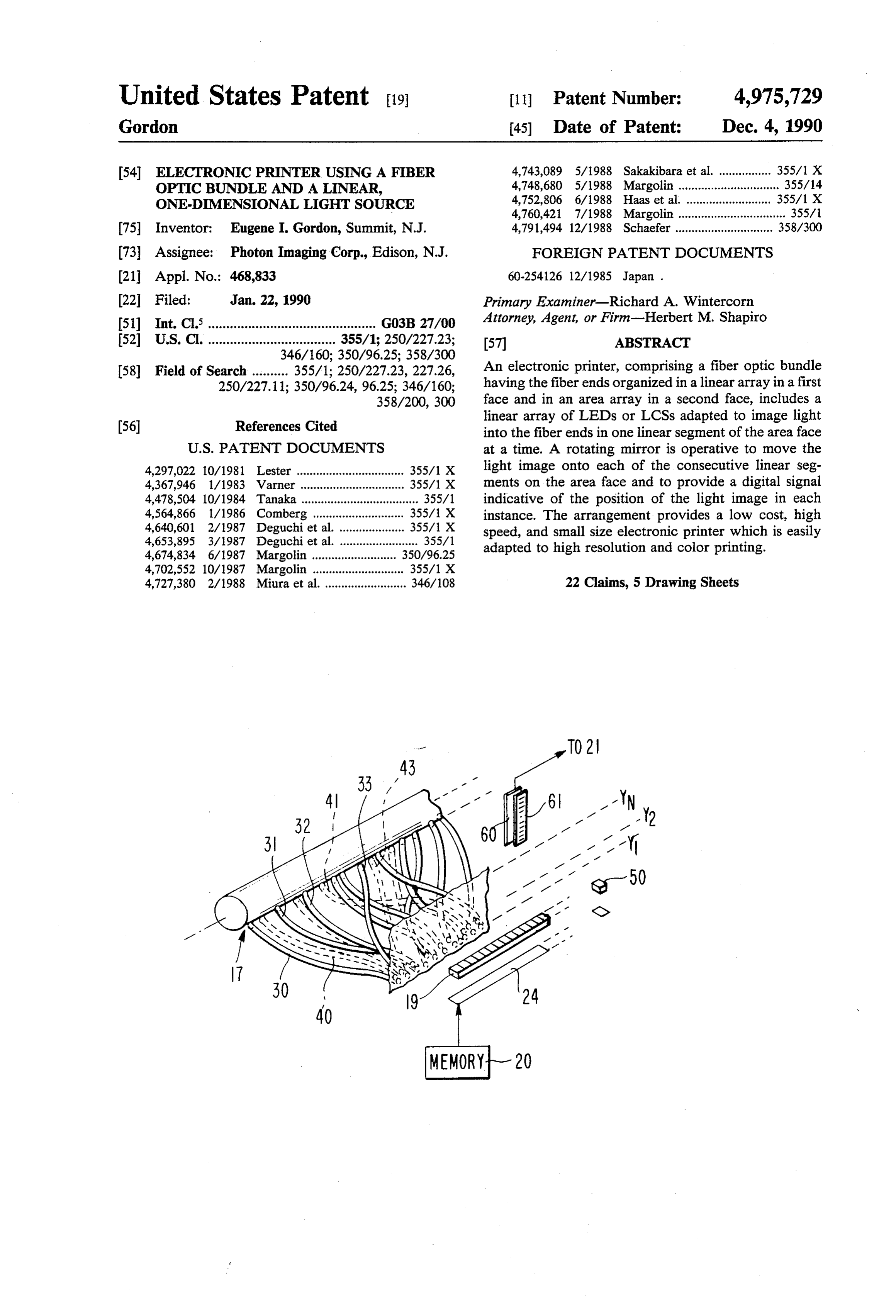
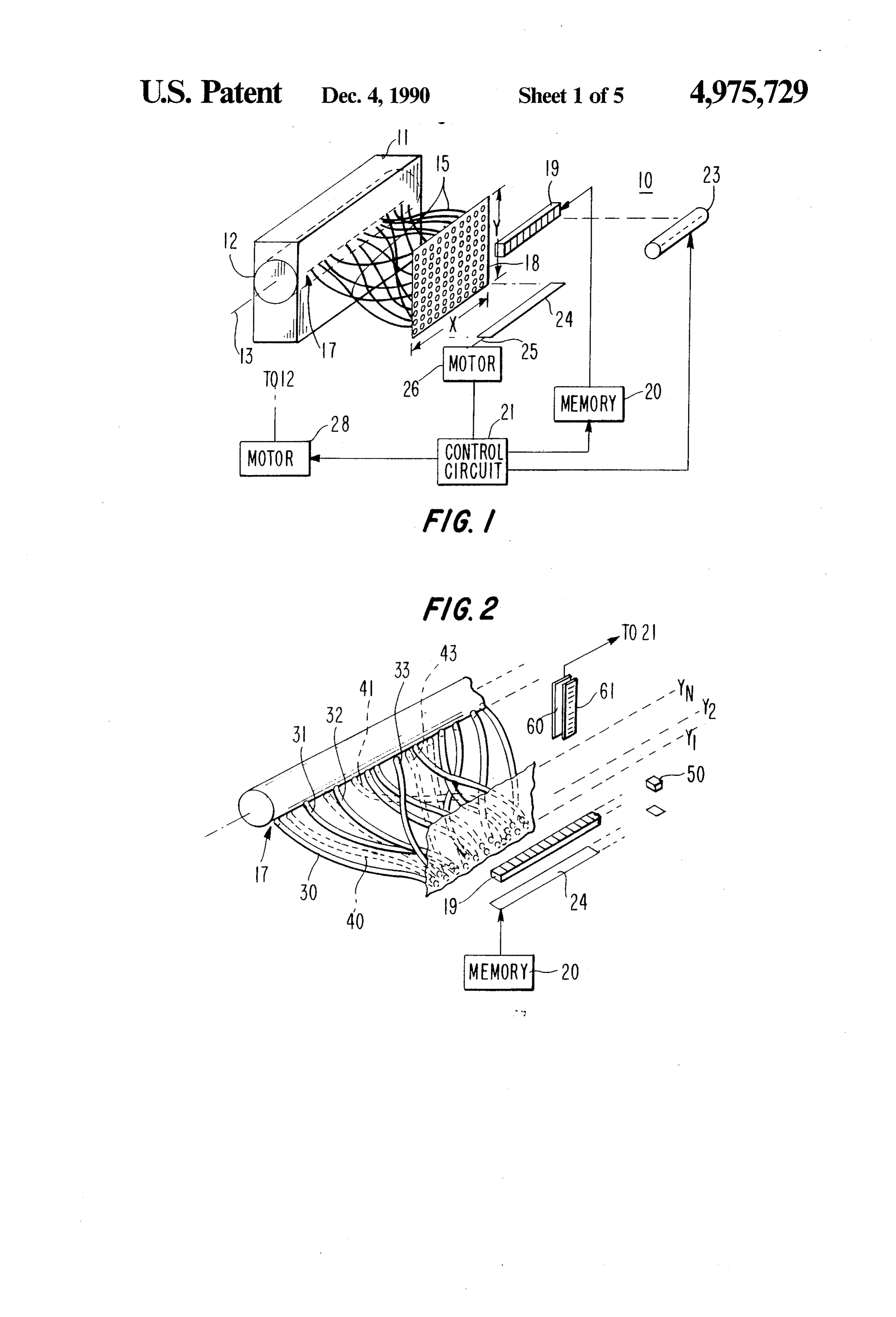
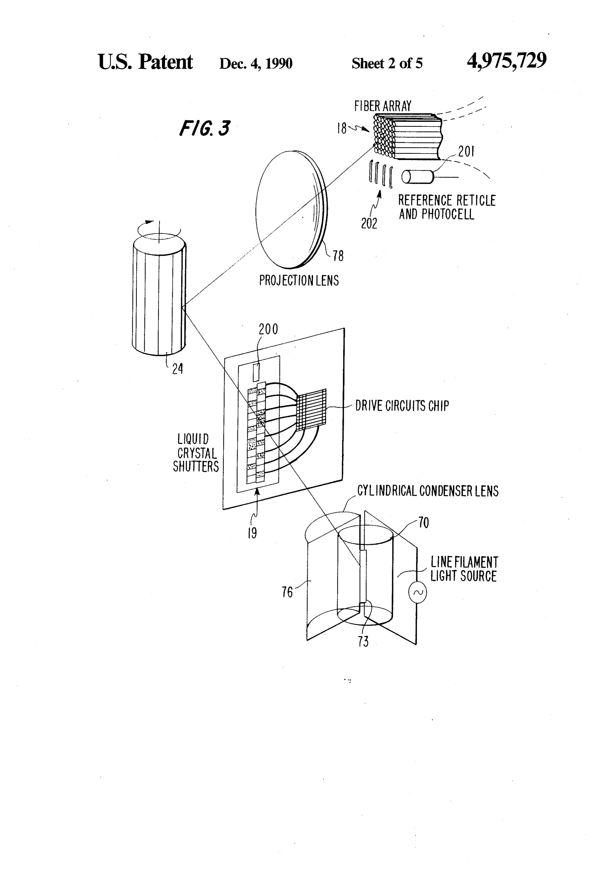
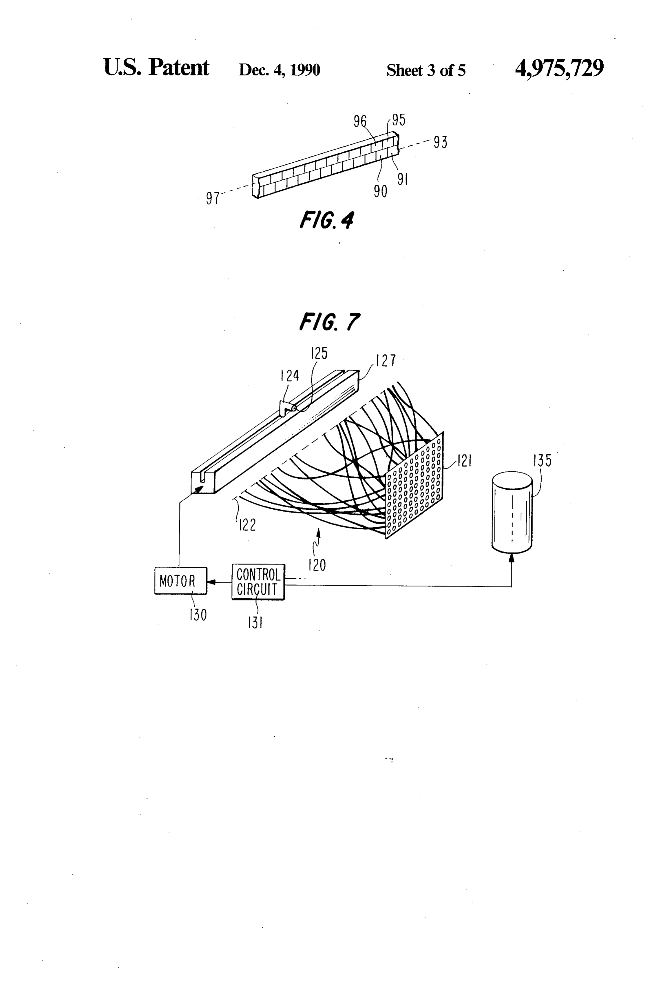
purposes, made stationary as the light spots are mir 55 BRIEF DESCRIPTION OF THE DRAWING rored consecutively onto the consecutive linear seg ment in the rectangular face of the fiber optic bundle. FIG. 1 is a representative block diagram of a printer The light spots corresponding to the totality of fibers engine in accordance with this invention; in the linear end of the fiber optic bundle are generated FIG. 2 is an expanded representation of a portion of during the time the mirrored image moves vertically the engine of FIG. 1;
through, for example, 100 discrete horizontal rows. FIG. 3 is a schematic representation of the compo This number actually corresponds to several times the nents of the engine of FIGS. 1 and 2; nominally thirty (virtual) rows of fibers in the area face FIGS. 4 and 5 are representative block and expanded of the bundle for the above-mentioned assumed number detail views of a component of the engine of FIGS. 1 of fibers for reasons that will became clear hereinafter. 65 and 2;
We will adopt the convention that the width of the FIG. 6 is a flow diagram of procedure for initializing rectangular area face is along an x-axis (the height is the optical subsystem of the printer engine of FIGS. 1 along a y-axis) and the image of the linear LED or LCS and 2; and
Page 9
FIG. 7 is a representative block diagram of apparatus It was noted above that there is an excess number of used for performing the method represented in FIG. 6. shutter elements in array 19 over the number of fibers DETAILED DESCRIPTION OF AN along the x axis of area face 18. Mirror 24 also is rotated
ILLUSTRATIVE EMBODIMENT OF THIS
in a manner so that memory 20 operates to move pixel
INVENTION
data into the LCS array 24 many times, say 100 times, during the rotation of the mirror over the area face.
FIG. 1 shows a printer engine assembly 10 in accor Thus, there are perhaps three times as many vertical dance with the principles of this invention. The assem addresses as there are fibers in the columns. The number bly comprises an image formation subassembly and an 100 rows times 256 elements per row (25,600) is approx optical subassembly. O imately ten times as many (xy) addresses at which light The image formation subassembly is represented as is generated than there are fibers in area face 18. This box 11. Box 11 comprises an illustrative, and commer means that there are about ten addresses dedicated for cially available, xerographic module including on elec each fiber. An initialization procedure need select only trostatic drum or belt, a toner station, a transfer station 15 one series of addresses for each fiber (one address if and a fixer station. This subassembly operates in a man sufficient light is provided) and is operative to deter ner well understood in the art to transfer to plain paper mine the series of addresses at which a maximum in a charge image formed on the electrostatic medium by light intensity occurs in each instance. The factor 10 optical exposure. The optical subsassembly is operative insures that this is so. Thus, the constraints on the posi to develop the charge image on the electrostatic me tioning of fibers in rows and columns in the area face are quite relaxed and, in practice, are totally disregarded dium. The electrostatic medium is represented by cylin 20 and its fibers can be organized entirely at random. This der 12 and is adapted to rotate about axis 13 as shown. is important
The optical subassembly for forming the charge one address tois achieve a low cost fiber bundle. At least selected from each series of addresses image on medium 12 includes a fiber optic bundle corresponding to a single fiber, the choice being made shown encompassed by imaginary tie 15. The fiber ends 25 to compensate for tearing.
are arranged linearly in a first face 17 of the bundle and Control circuit 21 also controls a motor 28. Motor 28 arranged illustratively in a rectangular geometry in a drives electrostatic medium 12 with which all the func second face 18. The area face can be represented as tions of the image-formation sub-assembly are synchro having x and y axes with the fibers arranged roughly in nized in a well known manner. Thus, it is clear that rows along the x axes. These rows are imaginary and 30 the row representation is used for simplifying the de control erly in circuit 21 moves the electrostatic medium prop synchronism with the movement of mirror 24 to scription only. It will become clear that the fibers are achieve a vertical pixel height approximately equal to not usually in rows (or columns) but that it does not the pixel width.
matter in any case. FIG. 2 shows an enlarged fragment of the electro The illustrative optical subassembly also includes a 35 static medium coupled to a corresponding fragment of linear array 19 of liquid crystal shutters (LCS's) opera the fiber optic bundle. The fibers 30, 31, 32, 33,-shown tive as light valves. The image of the array 19 extends by solid lines, all originate at the same row (2) in FIG. across the entire x axis of the area face of the fiber optic 2. It should be noted that the ends of these fibers at bundle. Array 19 also includes a number, N, of LCS linear end 17 are in no predictable positions there. Simi devices which is large compared to the number, S, of 40 larly, fibers 40, 41, 42, 43-originate at row y1 in area fibers along the x axis of the area face of the bundle. face 18 and again assume no predictable positions in Thus, for a 300 dpi resolution across on eight and one linear end 17. Yet because of the address sequence de half inch page, a rectangular (but random) array of termination of the initialization procedure and because fibers approximately 30x90 is used where the ninety of the excess numbers of addresses over fibers and be fibers are positioned along the x axis and the thirty 45 cause the y-axis address is determined digitally and fibers are positioned along the y axis, the fiber positions because the x-axis position of the LCS in the array 19 is being entirely random and not actually occurring in known, the memory operates to provide the proper rows or columns. In this instance, a linear array of pixel data for each pixel at linear end 17 of the fiber LCS's would include perhaps 256 individual shutter optic array even though that array is totally noncoher elements. The excess number of elements over the num 50 ent.
ber of fibers in the row will be seen to be important as The y-axis address vector is determined conveniently explained below. by including an extra index element in array 19. The Linear array 19 is operated as a line of individual light extra index element is designated 50 in FIG. 2. The valves shuttering light according to data applied to it. extra element is termed "extra' because it does not Thus, an output of memory 20 is connected to array 19 55 correspond in position to any portion of area face 18 of and is operative to shift a set of data into array 19 under the fiber optic bundle. Rather, the light exiting element the direction of control circuit 21. Light, for LCS em 50 is directed onto a single sensor 60 through a mask 61. bodiments, is provided by a backplane lamp 23 and is Mask 61 includes a grid of opaque and transparent selectively shuttered by the LCS device. spaces (an optical grating) which responds to the posi Any light exiting LCS array 19 is directed at a mirror tion of the light exiting element 50 to represent the 24. Mirror 24 is rotated about its axis 25 by a motor 26 y-axis address vector corresponding to the image of the also under the direction of control circuit 21. Axis 25 is linear light source array. Alternatively, sensor 60 may aligned with the x axis of area face 18 of the fiber optic comprise, for example, a photosensor array to provide bundle. Thus, when mirror 24 is rotated through a suc the y-axis vector for each image position. Such an ar cession of positions, the light from LCS array 19 is 65 rangement does not require mask 61. The x and y ad imaged onto consecutive y positions of the linear seg dresses for each pixel are determined during the initial ments of the area face where the long dimension of each ization procedure and stored in a PROM considered linear segment is parallel to the x axis of the area face. part of control circuit 21. The operation of the PROM
Page 10
is analogous to that of its counterpart in the above of about 4 watts/cm2. The required continuous optical noted patent. power incident on the shutter is 2.6 m watts. The re FIG. 3 shows a schematic representation of the vari quired optical power from the lamp is about 0.2 watts. ous elements of the optical subassembly of FIG. 1. A 100 watt Tungsten filament operated at 3200 degrees Lamp 70 is shown as having a filament 73. The subas k has adequate brightness to produce this even with sembly also includes a reflector or metallized coating filtering.
(not shown) used (in practice) to double the light intro The shift register driver chips for the shutter can be duced into the system by the lamp. Light from lamp 70 attached directly to LCS array 19 as shown in FIG. 3. is transmitted by condensing lens 76 to LCS array 19.
The light pattern passing LCS array 19, in each in 10 The description has been rendered in terms of a LCS stance, is directed to the mirror (24) for reflection onto shutter arrangement. Other arrangements also can be a linear segment of the area face 18 of the fiber optic used such as light emitting diodes (LED's), magneto bundle through projection lens 78. optic light valve and edge-emitting, thin film, electrolu LCS array 19 has been described as a single linear minescence devices (EE-TF-EL). Of these, LED and array of liquid crystal light valves. In practice, array 19 15 magneto-optic devices are already being used in existing might be arranged in other than a single linear row, for printer engines and are useful for printer engines in example, in two rows assembled like bricks in a wall accordance with the principle of the present invention where the bricks of one row are offset one half brick also.
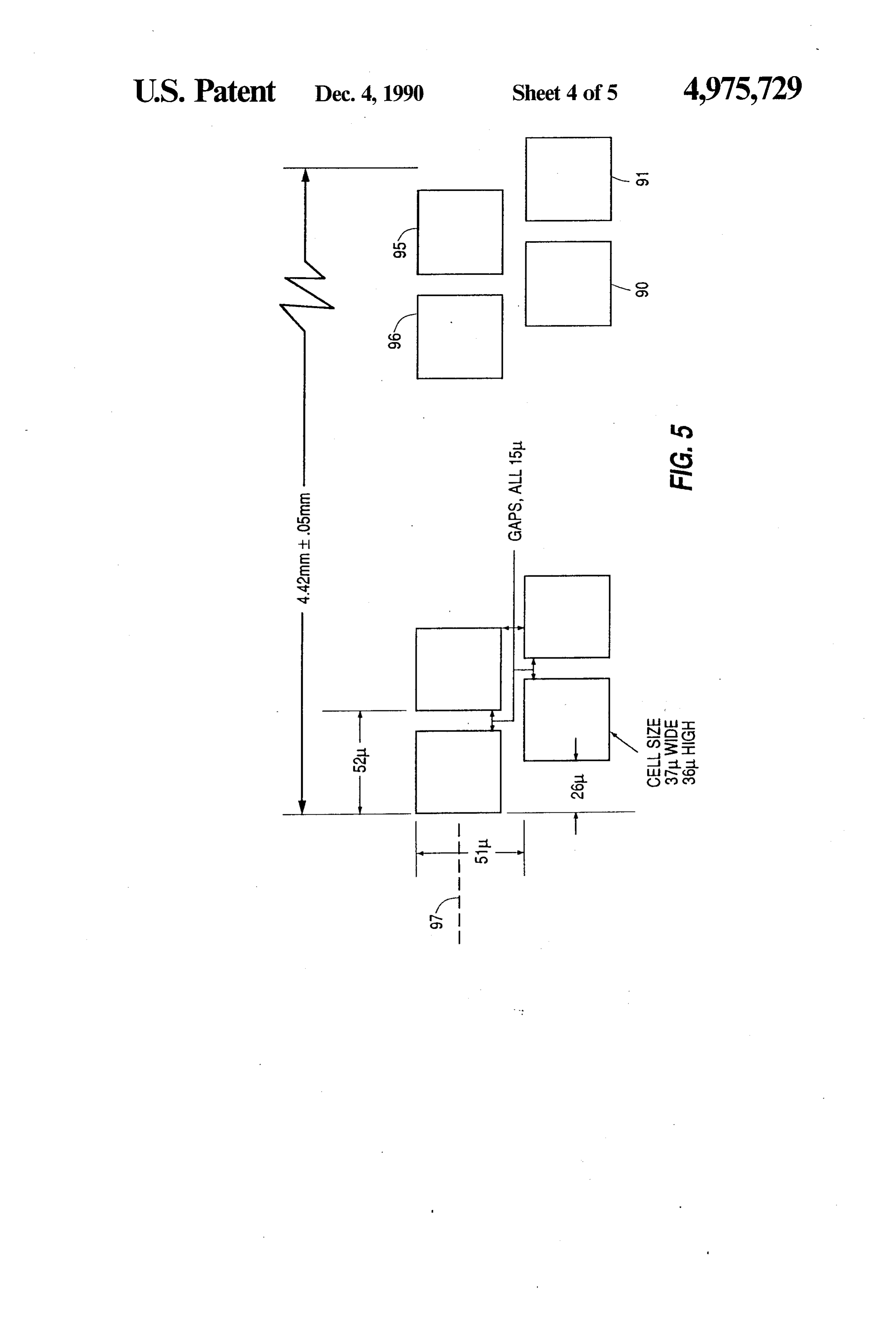
from the bricks in the next row. The arrangement is The suitability of such alternative devices herein is shown in FIGS. 3 and 4 where elements 90 and 91 in 20 underscored by the following illustrative calculations: row 93 are shown offset from elements 95 and 96 in row 97. FIG. 5 shows the array in greater detail showing an We will assume an exposure value requirement of 5 LCS cell size of 37 u wide by 67 u high and intercell ergs/cm2 which translates into 3.6X 10⁻¹¹ J/pixel. The transmission factor, TF, for a Lambertian emitter such gaps of 11.15 L. Such a LCS array is available commer cially from Displaytech Inc. of Boulder, Colo. The 25 as LED can be shown to be arrangement displayed for the liquid crystal shutters in
FIG. 3 is consistent with the brick-like LCS organiza tlOn.
The operation of the printer engine of FIGS. 1 and 2 in which F is the F-number of the lens and M is the can be summarized as follows: The data to be printed on 30 linear magnification, i.e. the linear dimension of the spot a page is already stored in memory 20 which may be a in the plane of the fiber array divided by the linear computer memory such as a disk. Memory 20 shifts dimension at the emitting array. shutter (open and closed) data into LCS array 19. Mir As a matter of interest, since the size of the LED ror 24 directs the resulting light pattern to a linear seg array element is potentially a variable, one should con ment of area face 18 of the fiber optic bundle for expos 35 sider the implications of that choice. The spot size on ing medium 12 to a discharge pattern. Memory 20 shifts the fiber is fixed. Thus, M is the variable. The energy a next subsequent pattern into LCS array 19. Mean available from the array element at constant brightness while, mirror 24 rotates to a position corresponding to is proportional to its area. Thus, M2 is the available the next linear segment of area face 18 and medium 12 moves perpendicular to the linear array of pixels. The 40 energy variable. The energy transmitted to the fiber at process repeats until the entire stored image is recorded constant brightness is, thus, on medium 12.
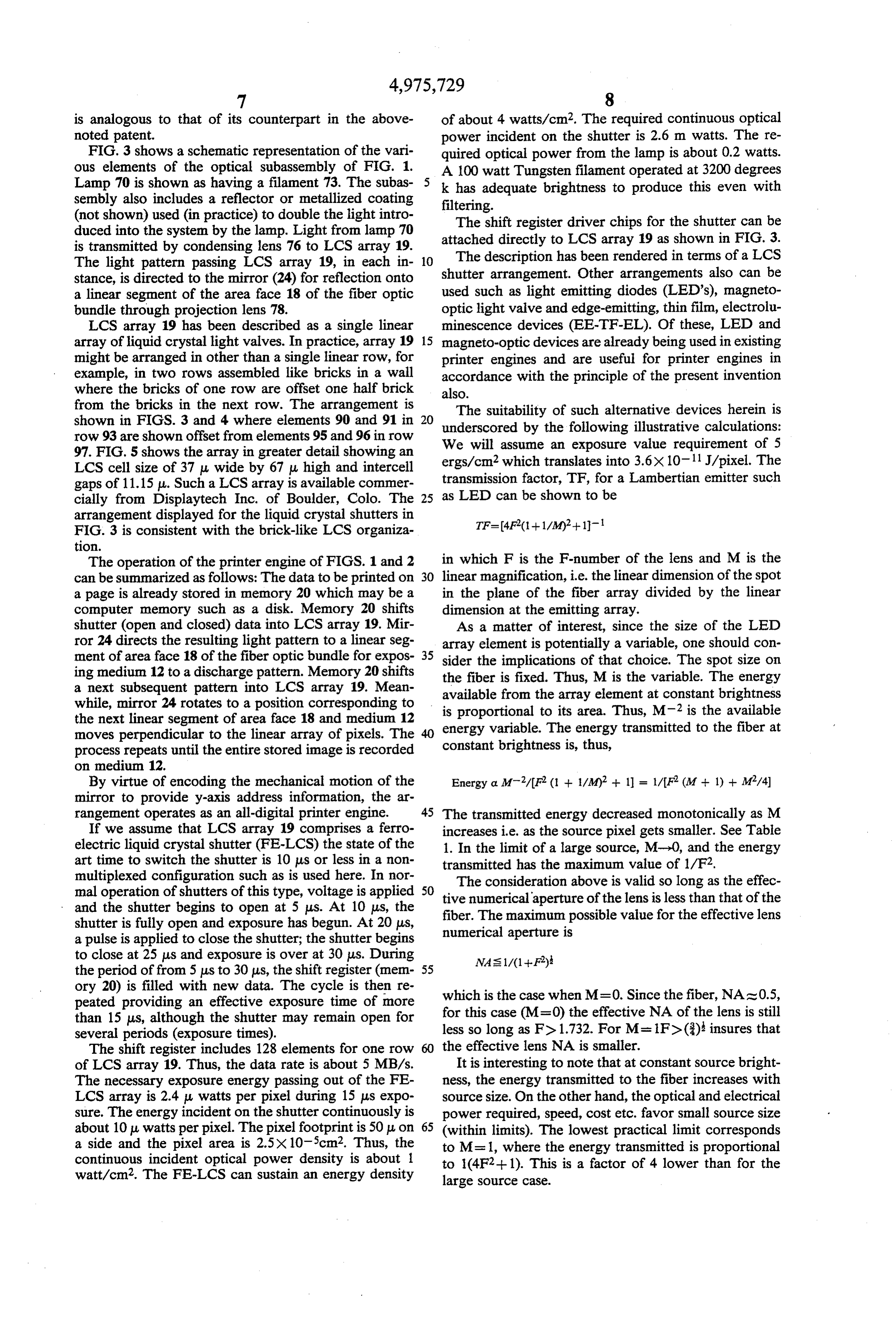
By virtue of encoding the mechanical motion of the Energy a M-2/F2 (1 + 1/M)2 + 1) = 1/F (M + 1) + M2/4) mirror to provide y-axis address information, the ar rangement operates as an all-digital printer engine. 45 The transmitted energy decreased monotonically as M If we assume that LCS array 19 comprises a ferro increases i.e. as the source pixel gets smaller. See Table electric liquid crystal shutter (FE-LCS) the state of the 1. In the limit of a large source, M-0, and the energy art time to switch the shutter is 10 us or less in a non transmitted has the maximum value of 1/F2. multiplexed configuration such as is used here. In nor mal operation of shutters of this type, voltage is applied 50 tiveThe consideration above is valid so long as the effec numerical aperture of the lens is less than that of the and the shutter begins to open at 5 us. At 10 us, the fiber. The maximum possible value for the effective lens shutter is fully open and exposure has begun. At 20 us, a pulse is applied to close the shutter; the shutter begins numerical aperture is to close at 25 us and exposure is over at 30 us. During NAs 1/(1 + F) the period of from 5 us to 30 us, the shift register (mem 55 ory 20) is filled with new data. The cycle is then re peated providing an effective exposure time of more which is the case when M=0. Since the fiber, NAS0.5, than 15 us, although the shutter may remain open for for this case (M=0) the effective NA of the lens is still several periods (exposure times). less so long as F> 1.732. For M= 1 Fd (3)} insures that The shift register includes 128 elements for one row the effective lens NA is smaller. of LCS array 19. Thus, the data rate is about 5 MB/s. It is interesting to note that at constant source bright The necessary exposure energy passing out of the FE ness, the energy transmitted to the fiber increases with LCS array is 2.4 L watts per pixel during 15 us expo source size. On the other hand, the optical and electrical sure. The energy incident on the shutter continuously is power required, speed, cost etc. favor small source size about 10 u watts per pixel. The pixel footprint is 50 u, on 65 (within limits). The lowest practical limit corresponds a side and the pixel area is 2.5X105cm2. Thus, the to M= 1, where the energy transmitted is proportional continuous incident optical power density is about 1.
watt/cm2. The FE-LCS can sustain an energy density to 1(4F2+ 1). This is a factor of 4 lower than for the large source case.
Page 11
TABLE 1 no two-dimensional, addressable, light-generating
EXPOSURE FACTOR 6aS such 2S a CRT 1S present. Instead, a linear, light - - generating means is made two-dimensional by rotating a F 0 0. 0.5 1 2 mirror which sweeps an image of a linear array of light 5 generating means onto consecutive linear segments of s d 44 8: 8: g 8. the area face of the fiber optic bundle, the light patterns 2 0.25 0.21 0.11 0.06 0.03 being changed "on the fly.” 2.5 0.16 0.13 0.07 0.04 0.02 In operation of the illustrative optical subassembly, 3 0.11 0.09 0.05 0.03 0.01 eigh bits (x axis bits) of a sixteen bit address code are EXPOSURE FACTOR = 1/(F(M + 1) + M/4} 10 supplied by an address register (not shown) which is part of the linear LCS array 19. The other eight bits (y
In one practical arrangement, there are two rows of axis bits) are supplied by sensor 60 and mask 61 to corre LEDs, perhaps 128 in each row, so that there are a total spond to the angular orientation of mirror 24. In an of 256 pixel addresses covering 90 fibers in a linear arrangement where mirror 24 of FIG. 1 is an elongated segment of the area face of the bundle. The LEDs are 15 polygon as shown in FIG. 3, for example, and motor 26 driven on the two sides in a 1x256 configuration (i.e. of FIG. 1 is a stepper motor, the mirror can be main no multiplexing). When the linear segments are scanned tained in consecutive fixed positions during an initializa vertically, there will be about 100 address positions tion procedure. In this instance, the relationship be covering about 30 fibers in a column. This provides tween the pixel positions in the linear end and those enough spatial coverage for about 2700 fibers. The 20 addresses are determined during the initialization proce linear dimension of the LED is about equal to the fiber dure by opening all light valves of LCS array 19 and by diameter, i.e. 85 microns. We want this to be about 28.33 microns in the image plane. Thus, the magnification is directing segment light through all the open shutters to a linear of the area face. While light is incident on all of 28.3/85=0.333. Assuming an F:2 lens, the transmission the instant linear segment, a hooded sensor with a trans factor is 0.02. For a large pixel, say four times larger, the 25 parent slit is moved along the linear face of the bundle magnification is 0.1 and the transmission factor is in increments small compared to a fiber diameter. In this 2.1 x 10⁻³ or 10 times lower. However, the available manner, all slit positions for which maximum intensity energy is at least 16 times greater. Hence, we gain a peaks factor of almost two by using larger LEDs. The actual obtained. The light valves remain on andseetheFIG. occur for that linear segment (i.e. 2) are gain from using larger LEDs may be much greater. 30 repeated for the next linear segment. The process conis process Large LEDs offer substantial opportunities for improv tinues until all the linear segments are exposed. At this ing brightness. The maximum line time is 3 ms corre juncture in the initialization procedure, all the maxi sponding to a 10 second page print time. Thus, 30 us is mum intensity positions and associated addresses are available to achieve the necessary exposure.
The necessary power out of the LED is 60 uwatts. to correspond to the 35 known but not in the order in which they have to occur order of the pixels desired at the
With reflection losses of about 15% this requirement linear face of the bundle. This relationship can be under becomes 70 uwatts. We assume that the LED emits 20 stood by an examination of the interleaved fibers shown uwatt/ma. This corresponds to a power efficiency of about 1.3%, typical of small, diffused-junction LED in The FIG, 2.
proper sequence for those addresses is obtained arrays in GaAlAs. Thus, the drive current requirement 40 by opening shutter only those shutters (LCS's) of array is 3.5ma to achieve 70 uwatts. This is a reasonable drive 19 at addresses (x and y) which correspond to one of the current for such a small LED. The LEDs tend to satu rate with increasing drive current. On the other hand, amaximum intensity positions previously obtained one at time while the hooded photosensor is in one of the there are 256 LEDs driving 2550 (nominally 2700) fi bers. Thus, each LED is used 9 times in each frame on 45 consecutive maximum intensity positions. The address the average. The duty cycle is, therefore, 270 us/3000 for which light exits at the photosensor position is re corded in each instance as described above. It takes us=0.09 under the assumption of uniform usage. Over heating is not a problem because the average drive about 100 ms to move the hooded photosensor to a new current is only 0.3 ma. fiber (pixel) position and scan the mirror. Thus, the total In presently available high speed LED line printers, 50 line time is 255 seconds for 2550 fibers. the LED on time is probably of order 60 us. The expo subassembly The physical organization of the illustrative optical sure requirement is the same. The NA of a suitable permits illumination, by a separate source, selfoc lens array is 0.1-0.2 at best. Thus, the energy of the entire area face of the fiber optic bundle at the transmission factor can be estimated to be less than 0.04 same time rather than by illumination of only one linear and probably comparable to the value assumed for the 55 segment of the area face at a time. The illumination of printer of 0.02. Therefore, the LED approach also ap the entire face at the same time allows all the maximum pears feasible, the trade off being the extra cost and intensity positions and related addresses to be obtained drive current requirements of the large LED array with a single scan of the linear face by the hooded pho versus the smaller number of LEDs required. tosensor. For the illustrative system where one hundred The initialization procedure for the optical subsas 60 y-axis positions are used, the illumination of the entire sembly of the printer engine of FIGS. 1 and 2 is directed area face reduces the scan time by a factor of one hun at determining the addresses of light imposed on the dred.
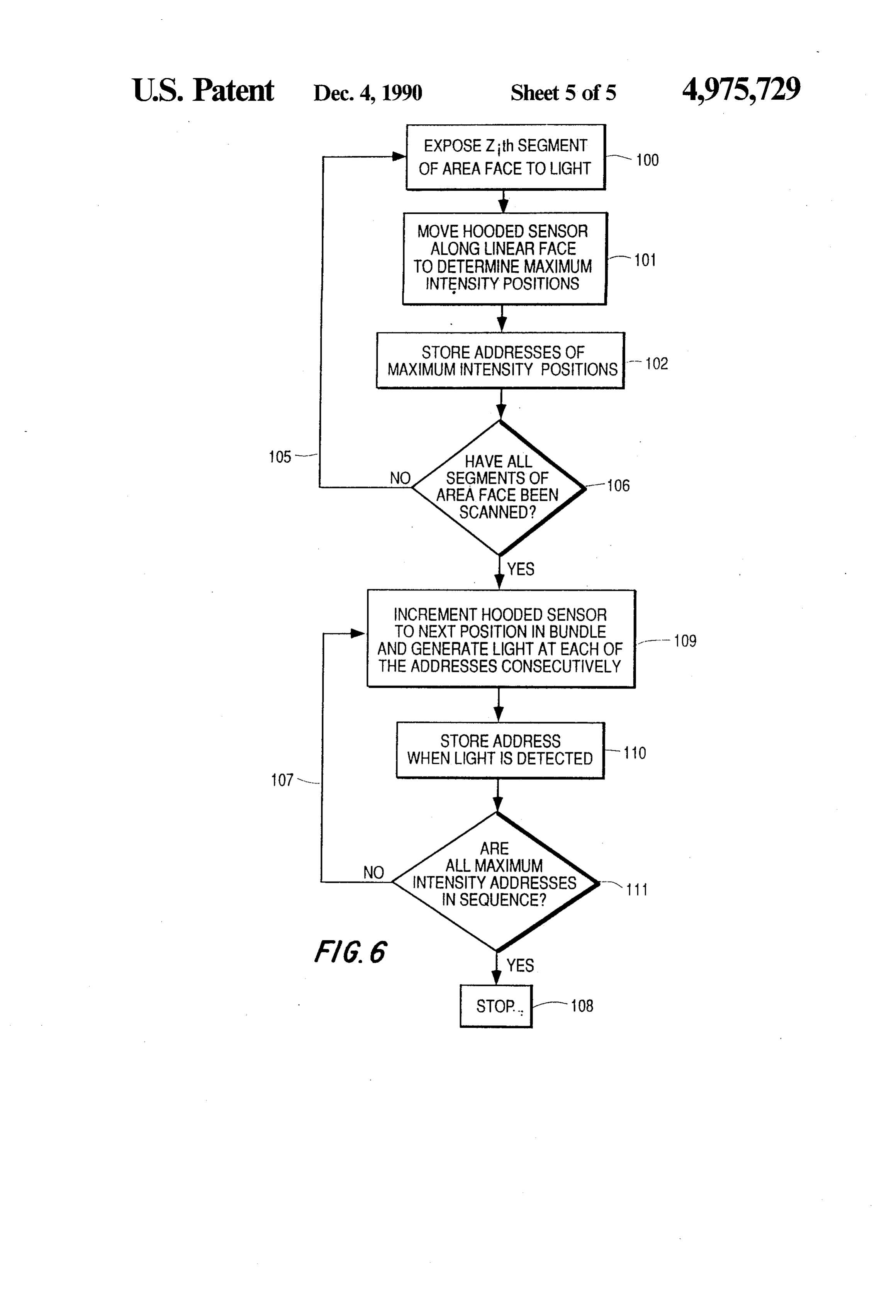
area face 18 of the fiber optic bundle and the relation FIG. 6 shows a flow diagram of the initialization ship between those addresses and the pixels exiting the procedure where the linear face is scanned by the linear face 17 of that bundle. In the absence of the estab 65 hooded photosensor each time a linear segment of the lishment of such relationship, light patterns directed at area face is illuminated. Block 100 indicates that a linear the area face will be scrambled at the linear face. In segment of the area face is illuminated. Block 101 indi accordance with the principles of the present ivention, cates that the hooded sensor is moved to determine all
Page 12
addresses at which maximum light intensity occurs. at the right position in the written line on the photosen Block 102 indicates that those addresses are stored. This sitive medium. The indexing light source (shutter) is procedure is repeated until light has been generated at designated 200 in FIG. 3. The photodetector is desig all linear segments as indicated by arrow 105. It is help nated 201 and the timing signals are designated 202. ful to remember that there are about ten addresses at the 5 Polygon 24, in one specific embodiment is a 20 facet, 38 light generating end of the optical subassembly to corre mm radius mirror arrangement and lens 76 is a 50mm, spond to each fiber. The sensor selects the set of ad F/3.1, 1:1 focussing lens.
dresses, amongst the ten for each fiber, at which the In a typical scan configuration, there are at least 100 maximum intensity occurs. It is also helpful to observe linear segments and 256 elements in the segment (and from FIG. 2 that the addresses at which maximum in 10 the segments may overlap). Thus, there are for any tensity occur in one linear segment of the area face are segment on average, about 25.5 elements thar are in the interleaved with the addresses from other segments. correct position to excite a fiber. Each segment is in its After all linear segments are scanned by the photo position for 25 us. The 100 segments are executed in sensor as indicated by block 106, the addresses of maxi time sequence with no dead time. Thus, the time to mum intensity positions are placed in a sequence to 15 write a linear segment of the page is 2.5 ms with a cycle correspond the sequence of pixels in the linear face of time of 3 ms to cover (inter-facet) dead time in the the fiber optic bundle. This is accomplished by moving polygon. With 3300 linear segments, it takes about 10 the slit (photosensor) to a now known position of maxi seconds to write a page. In a typical design, a polygon mum light intensity and, while the photosensor is in that with 20 sides performs the scanning. The time for one position, generating light consecutively at all the ad 20 complete turn of the polygon is 60 ms corresponding to dresses determined by the above procedure until the 1000 revolutions per minute. Each pixel in the linear photosensor detects light. The photosensor is then array is turned on every 10 rows on average or about 10 moved to the next consecutive position where maxi times during exposure cycle. Thus, 256 light sources mum light intensity occurred and the procedure is re write into 2550 fibers. The timing is consistent with 6 peated as indicated by arrow 107. When all elements at 25 pages per minute.
which maximum intensity light is generated are in se Groups of fibers in the fiber linear array emit light quence, the initialization procedure stops as indicated simultaneously. There is not a progressive sequence of by block 108. The scrambled addresses at which maxi light spots for exposing the pixels as in a flying spot mum light intensity occurred are now in an ordered (CRT) scanner. As a result there is the possibility that sequence corresponding to the desired ordered se 30 two adjacent fibers in the linear array would not be quence of the maximum light intensity (pixels) in the excited with a non trivial time gap as mentioned above. linear face of the bundle. The ordering procedure is With a continuously moving photosensitive medium, represented by blocks 109, 100, and 111 of FIG. 6. the pixels would exhibit small, random vertical dis FIG. 7 shows an arrangement for carrying out the placements from a straight line, never more than one initialization procedure. The fiber optic bundle 120 35 pixel. These displacements repeat from line to line so again extends from an area face 121 to a linear face 122 there would be a small tear between some vertical lines. as in FIG. 1. A photosensor 124 covered with a hood This would be undesirable. Fortunately, the distance having a slit 125 is moved along track 127. The incre between two fibers in the area face which are adjacent mental movement of the sensor is carried out by a motor in the linear face is typically a small fraction of the 130 under the control of control circuit 131 which may 40 length of the fiber optic bundle, area array side. Thus, be control circuit 21 of FIG. 1. Control circuit 131 the time lapse in writing the two adjacent fibers in the typically comprises a relatively fast computer pro linear array face is atmost a small fraction of the time to grammed for the initialization procedure operation. A write a horizontal line. During this time the photosensi much less sophisticated control circuit can be used for tive medium moves a distance equal to the height of one the finished printer. The control circuit (131) is opera 45 pixel. Consequently, the vertical displacement of adja tive, as is control circuit 21 of FIG. 1, to contro the light cent pixels and the related tear is never more than a generating means LCS 19 (or LED equivalent), the small fraction of the pixel height. On the other hend, if liquid crystal shutters, and mirror 24 and to synchronize the photosensitive medium is moved stepwise during the operation of the light-generating means with the the dead time of the polygon and is held stationary movement of sensor 124 along track 127. FIG. 7 also 50 during the writing period, then all pixels fall on the shows a lamp 135 for illuminating the entire area face of same straight line. Based on simulations, the small verti the fiber optic array if required by the chosen initializa cal displacements that occur with a continuously mov tion procedure. ing medium are not observable and it is not expected The image of the linear LCS light valve (LV) array that step motion will be necessary.
(19 of FIG. 3) is scanned mechanically by a rotating 55 The reason that fiber ends in the area face of a fiber polygon (24) across the area face 18 of the fiber optic optic bundle, which have adjacent ends in the linear bundle as described above. Particular shutters in the face, actually end up in closely-spaced (although ran linear array are turned on to transmit light into particu dom) positions is a result of the manufacturing proce lar fibers. The image of the linear array scans at approxi dure for the fiber optic bundle. Optical fibers are drawn mately constant velocity across the area face (18) of the 60 and captured on a drum in a manner well understood in fiber optic bundle. An index light source at the end of the art. A fiber optic bundle is made from these cap the linear LCS array generates timing signals from a tured fibers by placing an adhesive tape across the fi transmission grid photodetector in the plane of the area bers, say every foot along the drum and by cutting the face of the fiber optic bundle immediately adjacent to fibers at the tape. The fibers thus, are captured in a the fiber array. In response to the timing signals, the 65 linear arrangement at one end and just hang at the system turns on the particular pixels in the row at just other.
the right time to excite the appropriate fibers. The in The LCS array is controlled by dedicated drivers; it coming pixel stream is reordered so as to produce pixels is not multiplexed. The elements comprise a special,
Page 13
high speed liquid crystal shutter with cross polarizers. vice light valve (LCS-LV), and memory means for Typical contrast ratio exceeds 500:1. Since there are on shifting into said LCS-LV data for controlling the open average five LCS elements potentially illuminating or shut states for the shutter elements therein. each fiber core, a non excited fiber receives about 5 time 4. A combination of elements in accordance with the dark output of one element. So the actual contrast 5 claim 3 wherein said means for controlling a plurality of ratio of the emission into the fiber is about 100:1. light elements comprises mirror means for reflecting The excitaion wave form is a -- 15 v pulse for black light from said LCS-LV to said area face and means for and a -15 v pulse for white. The light turn-on and rotating said mirror means controllably for directing turn-off is delayed by about 7 us and the 10 to 90% rise reflected light to said consecutive linear segments. time is also about 7 us. Thses parameters are voltage 10 5. A combination in accordance with claim 2 wherein and temperature dependent so the voltage and tempera said means for controlling said light elements includes ture of the cell are controlled. Because of the rise time, control means for rotating said mirror to produce con the 25 us light pulse is roughly bell-shaped with a flat secutive images along said second axis corresponding to tened top, thereby slightly reducing the available light. said linear segments.
This further reduces the contrastratio, but not by much, 15 6. A combination in accordance with 2 wherein said perhaps 20%. The shutter without polarizers has an plurality of light conduits comprises a fiber optic bundle absorption loss of % and can handle a kilowatt/cm2 of including fibers arranged randomly in a two-dimen optical flux. However, even with a polarizer/cell sand sional arrangement of S fibers along said first axis and T wich and no cooling, the rated incident optical power fibers along said second axis, wherein said linear means capability is 4 watts/cm2. 20 comprises N devices where N>> S, said combination The total flux in the pulse can be varied by control also including second-axis control means for controlling ling pulse width or height, so gray scale is inherient. said means for controlling such that light from linear Gray scale also can be achieved by time modulation. means is directed at a number, Z, of consecutive linear Color can be achieved by putting three linear fiber segments where Zd >T.
arrays together in parallel in the same fiber optic bundle 25 7. A combination in accordance with claim 6 wherein using separate drive sources. The fiber lines are spaced ZN is ten or more times greater than S.T. by one pixl height. The color for three adjacent lines are 8. A combination in accordance with claim 2 wherein written simultaneously with appropriate delay so that said light conduits comprise a fiber optic bundle, said they superimpose on the photosensitive medium. Be combination also including a photosensitive medium cause of the geometry, registration is automatically 30 coupled to said linear face and responsive to light pat achieved. There is no writing time penalty i.e. the rate terns issuing from said fiber ends in said linear face for is still 5 or more pages per minute. Another option is to forming an image on the photosensitive medium. use time sequential color with stepped motion of the 9. A combination in accordance with claim 8 wherein medium. An initialization procedure for color embodi said photosensitive medium comprises an electrostatic ments requires, for example, three consecutive proce 35 medium with associated toner, transfer and fixer sta dures, one for each color with light of red, green and tions for forming an image on plain paper. blue, where each procedure is analogous to that de 10. A combination in accordance with claim 8 scribed above. The procedures also may be carried out wherein said photosensitive medium comprises photo by using a color wheel. graphic paper.
Although the invention has been described in terms 11. A combination in accordance with claim 2 of a linear array of light sources and a mirror, it should wherein said light conduits comprise a fiber optic bun be clear that a matrix array can be used in a row by row dle, wherein said light source means comprises means mode to achieve the equivalent operations. Also, one or for directing light at said linear means, and said linear more linear array of light sources can be imaged onto an means comprises light shutter means for controllably area face of a fiber bundle which is in the shape of an 45 occluding said light.
annulus where the images are rotated by, for example, a 12. A combination in accordance with claim 8 also Dove Prism to move from (radial) segment about the including a light source for directing light at said linear annulus. means and light shutter means for controllably occlud What is claimed is: ing said light.
1. A combination comprising a plurality of light con 50 13. A combination in accordance with claim 6 duits having the ends thereof arranged in a linear array wherein said linear means comprises an LED and said in a first face and in an area array in a second face hav means for directing comprises mirror means responsive ing first and second axes and a plurality of linear seg to coded signal for moving said mirror to direct light to ments parallel to said first axis, light source means for said linear segments.
generating a plurality of light elements simultaneously 55 14. A combination in accordance with claim 2 along each of said linear segments of said area face wherein said linear means comprise a plurality of LCS aligned with said first axis and digital means for control light valves arranged in first and second rows offset ling the presence or absence of said light elements at from one another.
said linear segments along said second axis of said area 15. A combination in accordance with claim 2 also face each of said linear segments extending across said 60 including sensor means for sensing the one of said linear area face along said first axis. segments illuminated and means responsive to said sen 2. A combination in accordance with claim 1 wherein sor means for providing a coded representation for said light source means comprises linear means for gen y-axis position of the illuminated linear segment in each erating said plurality of light elements and digital means instance.
for directing said light elements at consecutive ones of 65 16. Apparatus for initializing an optical system com said linear segments. prising a fiber optic bundle which has the ends of the 3. A combination in accordance with claim 2 wherein fibers arranged in a linear array in a first face and in an said light source means comprises a linear LCS multide area array in a second face and which has a linear ar
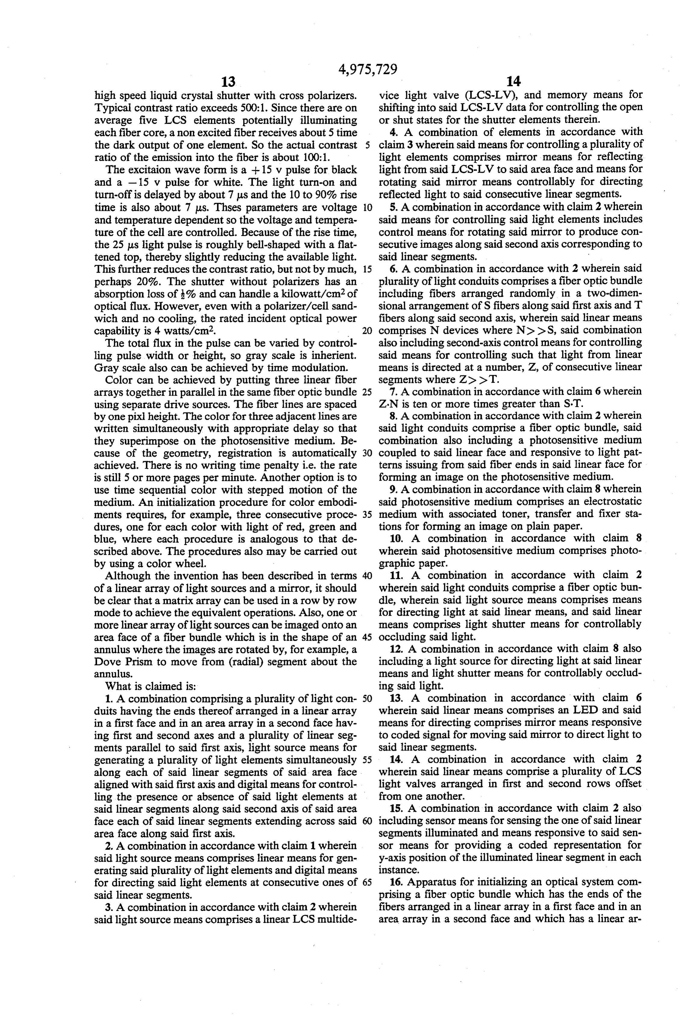
Page 14
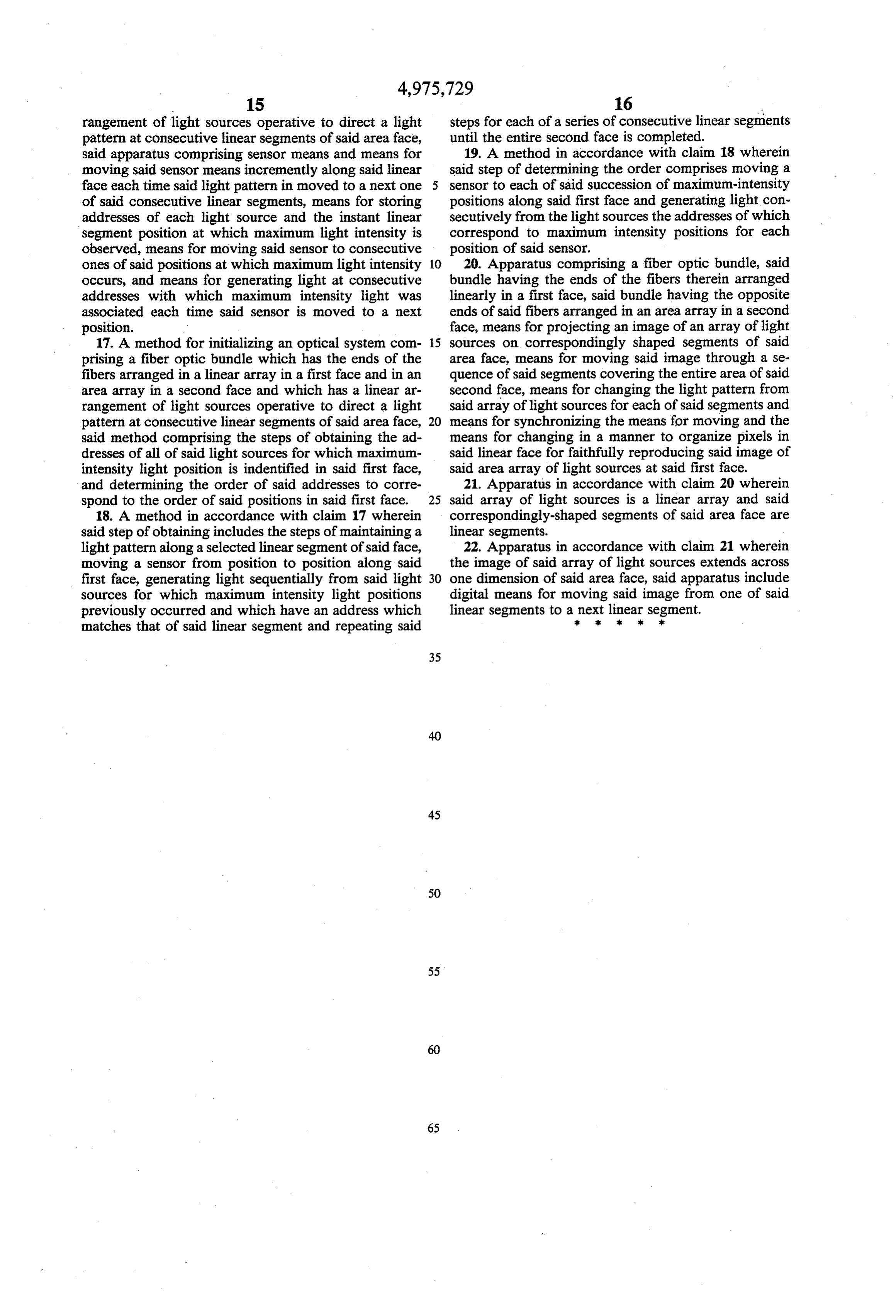
rangement of light sources operative to direct a light steps for each of a series of consecutive linear segments pattern at consecutive linear segments of said area face, until the entire second face is completed. said apparatus comprising sensor means and means for 19. A method in accordance with claim 18 wherein moving said sensor means incremently along said linear said step of determining the order comprises moving a face each time said light pattern in moved to a next one sensor to each of said succession of maximum-intensity of said consecutive linear segments, means for storing positions along said first face and generating light con addresses of each light source and the instant linear secutively from the light sources the addresses of which segment position at which maximum light intensity is correspond to maximum intensity positions for each observed, means for moving said sensor to consecutive position of said sensor.
ones of said positions at which maximum light intensity 10 20. Apparatus comprising a fiber optic bundle, said occurs, and means for generating light at consecutive bundle having the ends of the fibers therein arranged addresses with which maximum intensity light was linearly in a first face, said bundle having the opposite associated each time said sensor is moved to a next ends of said fibers arranged in an area array in a second position. face, means for projecting an image of an array of light 17. A method for initializing an optical system com 15 sources on correspondingly shaped segments of said prising a fiber optic bundle which has the ends of the area face, means for moving said image through a se fibers arranged in a linear array in a first face and in an quence of said segments covering the entire area of said area array in a second face and which has a linear ar second face, means for changing the light pattern from rangement of light sources operative to direct a light said array of light sources for each of said segments and pattern at consecutive linear segments of said area face, 20 means for synchronizing the means for moving and the said method comprising the steps of obtaining the ad means for changing in a manner to organize pixels in dresses of all of said light sources for which maximum said linear face for faithfully reproducing said image of intensity light position is indentified in said first face, said area array of light sources at said first face. and determining the order of said addresses to corre 21. Apparatus in accordance with claim 20 wherein spond to the order of said positions in said first face. 25 said array of light sources is a linear array and said 18. A method in accordance with claim 17 wherein correspondingly-shaped segments of said area face are said step of obtaining includes the steps of maintaining a linear segments.
light pattern along a selected linear segment of said face, 22. Apparatus in accordance with claim 21 wherein moving a sensor from position to position along said the image of said array of light sources extends across first face, generating light sequentially from said light 30 one dimension of said area face, said apparatus include sources for which maximum intensity light positions digital means for moving said image from one of said previously occurred and which have an address which linear segments to a : nextk linear sk x segment.
matches that of said linear segment and repeating said
Provenance
- Collection
- Cited prior art
- Original PDF
- patentimages.storage.googleapis.com →
- Filed
- 1990-01-22
- Pages
- 14
- Method
- pdftotext (the PDF's own text layer) + pdftoppm 300dpi page scans
- Source
- Google Patents bibliographic record
- Granted
- 1990-12-04
- Inventors
- Eugene I. Gordon; Photon Imaging Corp
- Transcribed from
- patentimages.storage.googleapis.com →