patent · US4813765
Device for changing directions of light rays
21 March 1989
Page 1
Drawing sheet — no readable text.
Page 2
United States Patent 19 11 Patent Number: 4,813,765 Negishi 45 Date of Patent: Mar. 21, 1989 54) DEVICE FORCHANGING DIRECTIONS OF FOREIGN PATENT DOCUMENTS
LIGHT RAYS
76) Inventor: Masataka Negishi, 29-19, Daito 56843 8/1982 European Pat. Off. ......... 350/96.10
2-Chome, Urawa-Shi, Saitama-Ken, 3208162 10/1982 Fed. Rep. of Germany 362/31 : - - Japan 1091225 4/1955 France .................................. 362/31 21 Appl. No.: 59,878 1363539 5/1964 France .............................. 350/96.10
(22) PCT Filed: Sep. 19, 1986 127925 10/1978 Japan. (86). PCT No.: PCT/JP86/00489 Primary Examiner-Jon W. Henry
Attorney, Agent, or Firm-Ladas & Parry
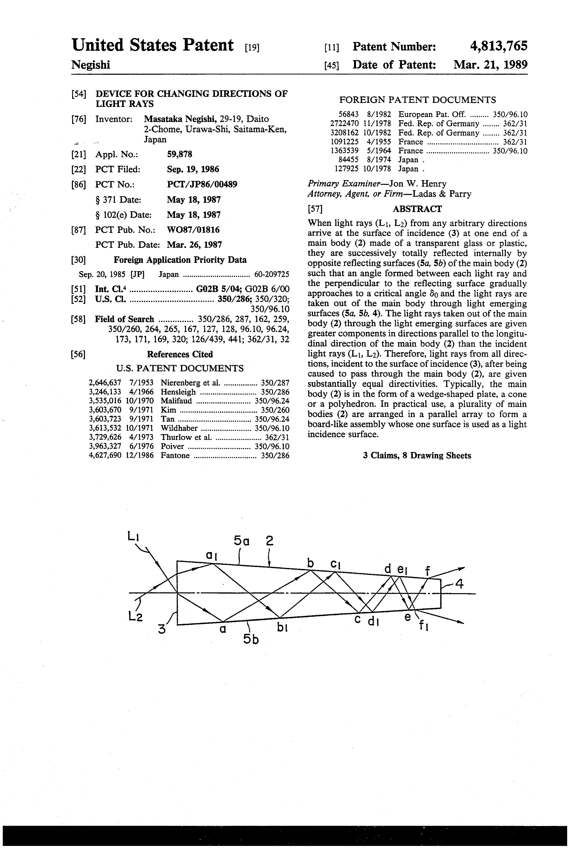
When light rays (Li, L2) from any arbitrary directions 87 PCT Pub. No.: WO87/01816 arrive at the surface of incidence (3) at one end of a PCT Pub. Date: Mar. 26, 1987 main body (2) made of a transparent glass or plastic, they are successively totally reflected internally by 30 Foreign Application Priority Data opposite reflecting surfaces (5a, 5b) of the main body (2) Sep. 20, 1985 JP Japan ................................ 60-209725 such that an angle formed between each light ray and the perpendicular to the reflecting surface gradually 51) Int. Cl."........................... GO2B5/04; G02B 6/00 approaches to a critical angle ào and the light rays are 52 U.S.C. .................................... 350/286: 350/320; taken out of the main body through light emerging 350/96.10 surfaces (5a, 5b, 4). The light rays taken out of the main 58 Field of Search ............... 350/286, 287, 162, 259, body (2) through the light emerging surfaces are given 350/260, 264, 265, 167, 127, 128, 96.10, 96.24, greater components in directions parallel to the longitu 173, 171, 169,320, 126/439, 441; 362/31, 32 dinal direction of the main body (2) than the incident 56) References Cited light rays (L1, L2). Therefore, light rays from all direc
caused to pass through the main body (2), are given 2,646,637 7/1953 Nierenberg et al. ................ 350/287 substantially equal directivities. Typically, the main 3,246, i33 4/1966 Hensleigh ........................... 350/286 body (2) is in the form of a wedge-shaped plate, a cone 3,535,016 10/1970 Malifaud .......................... 350/96.24 or a polyhedron. In practical use, a plurality of main 3,603,670 9/1971 Kim ..................................... 350/260 bodies (2) are arranged in a parallel array to form a 3,603,723 9/1971 Tan ................................... 350/96.24 3,613,532 10/1971 Wildhaber ........................ 350/96.10 board-like assembly whose one surface is used as a light 3,729,626 4/1973 Thurlow et al....................... 362/31 incidence surface.
3,963,327 6/1976 Poiver ............. . 350/96.10 4,627,690 12/1986 Fantone .............................. 350/286 3 Claims, 8 Drawing Sheets
Page 3
Drawing sheet — no readable text.
Page 4
Drawing sheet — no readable text.
Page 5
Drawing sheet — no readable text.
Page 6
Drawing sheet — no readable text.
Page 7
Drawing sheet — no readable text.
Page 8
Drawing sheet — no readable text.
Page 9
Drawing sheet — no readable text.
Page 10
they are refracted at the reflecting surfaces, being emit
DEVICE FOR CHANGING DIRECTIONS OF ted from the main body substantially at a predetermined LIGHT RAYS angle relative to the reflecting surfaces or the outer surface of the main body or being emitted within a
TECHNICAL FIELD predetermined angular range. As a result, the light rays The present invention relates to a device for changing emitted or emerging from the main body are almost in the directions of light rays and, more particularly, to a the same direction.
device for receiving light rays from all directions and converting them into light rays within a predetermined 10 BRIEF DESCRIPTION OF THE DRAWINGS range of direction. FIG. 1 is a sectional view of a main body according
BACKGROUND ART
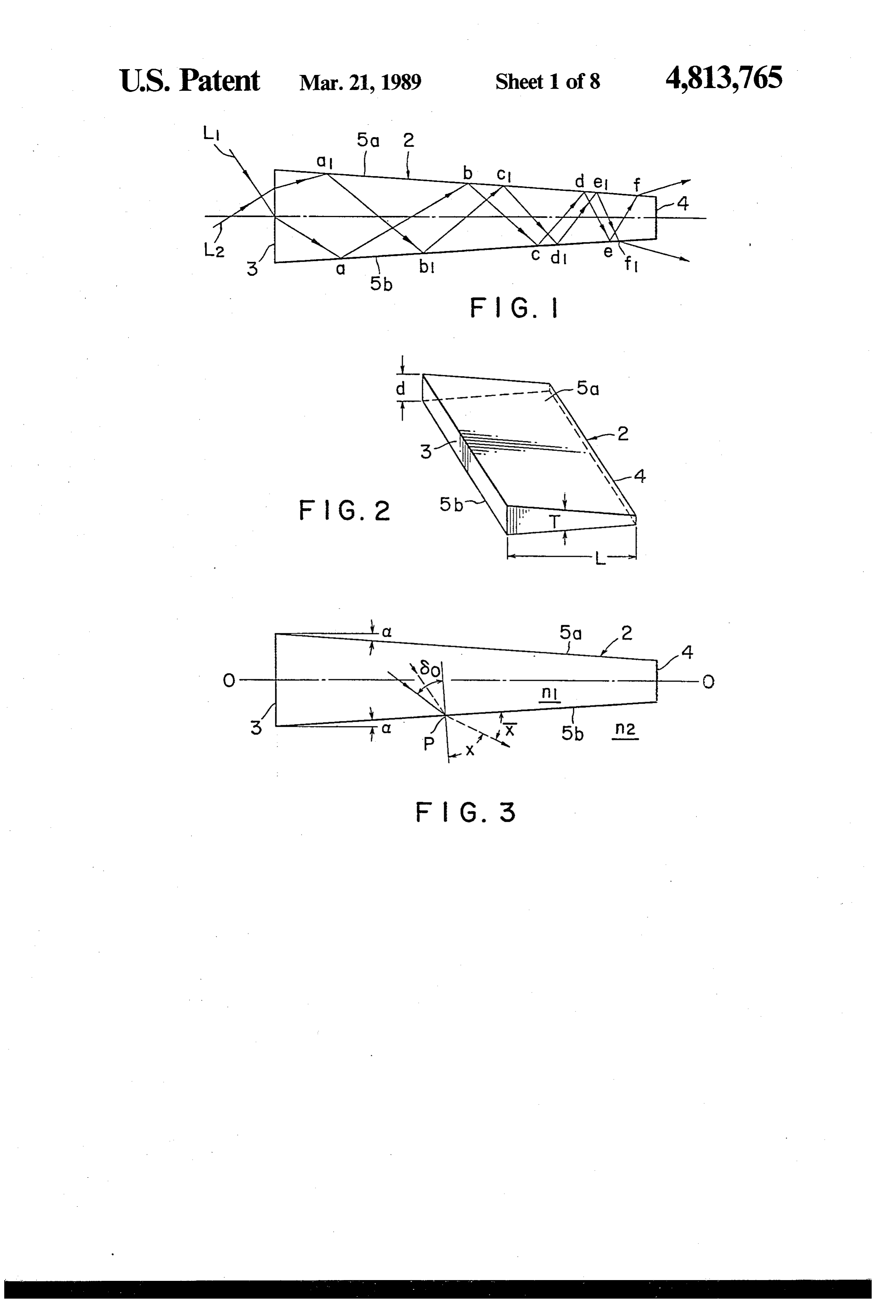
to a preferred embodiment of the present invention;
FIG. 2 is a perspective view thereof;
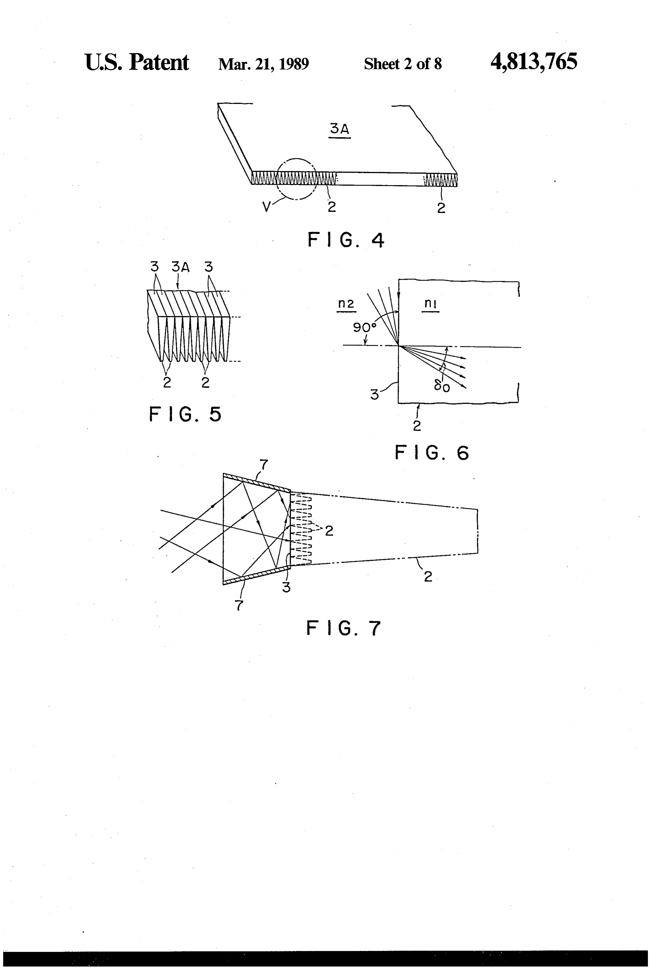
In the case of utilization of light, such as sunlight, FIG. 3 is a view explanatory of the mode of operation whose angle of incidence gradually changes, in order to of the first embodiment shown in FIG. 1; attain an effective utilization, a light source tracking 15 FIG. 4 is a perspective view of an assembly for device which is so controlled as to point to the direction changing the directions of light rays in which a plurality of incident light is needed. of main bodies as shown in FIG. 2 are arranged in a When a light input or reception means is always parallel array;
maintained to point to the direction of incidence of light FIG. 5 is an enlarged view illustrating a portion indi by the light source tracking device, the incident light 20 cated by V in FIG. 4;
can be received in a most effective manner. However, FIG. 6 is a view explanatory of the behaviors of light as the angle of incidence of, for example, sunlight grad rays incident on a light incidence surface; ually changes according to the season of the year and FIG. 7 is a sectional view of a device for assisting the from the sunrise to the sunset, an effective light source 25 incidence of light rays;
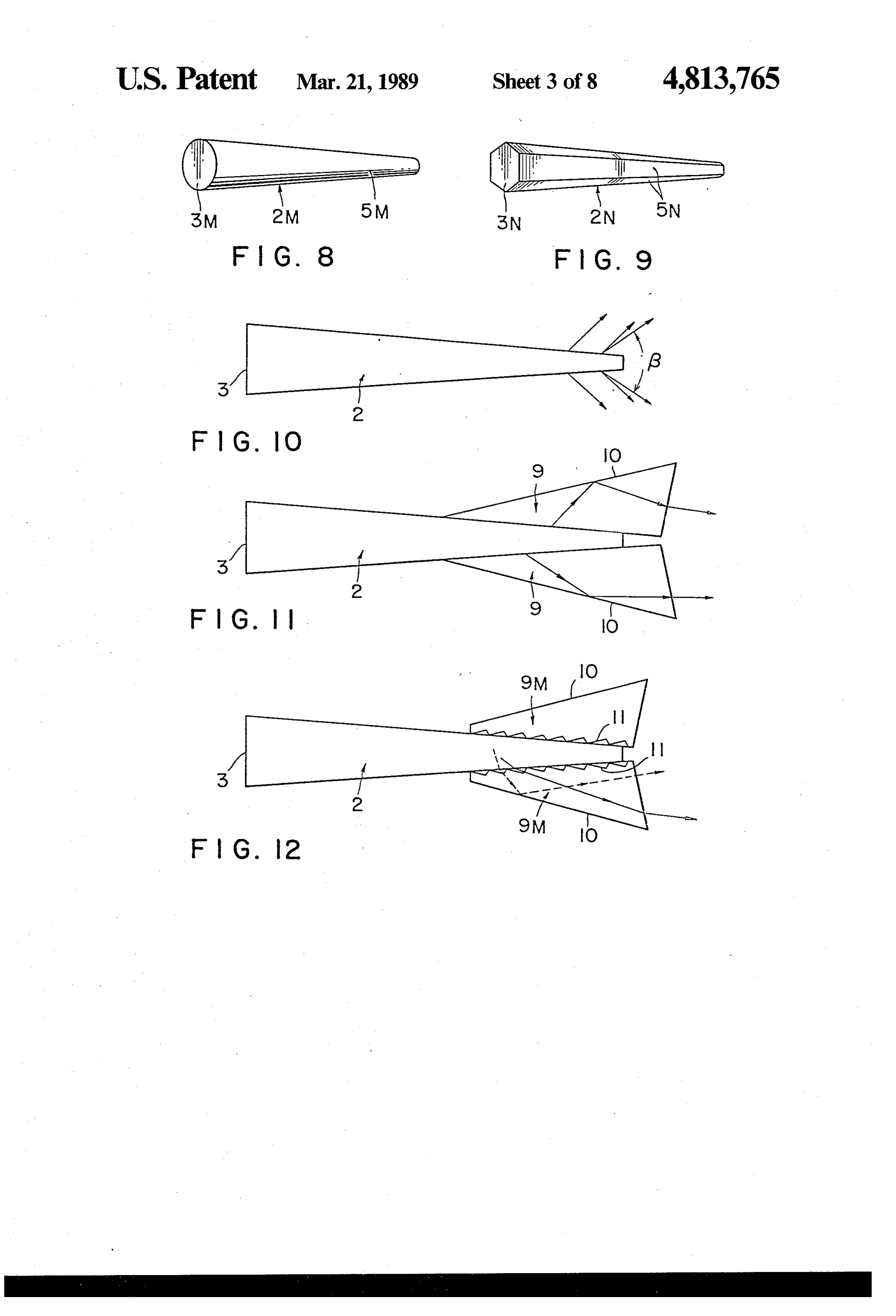
tracking device must necessarily be complicated in con FIG. 8 is a perspective view of a further preferred struction and expensive and cannot be used practically. embodiment of the present invention; The present invention has been made to overcome FIG. 9 is a perspective view of a yet further preferred the above and other problems encountered in the prior embodiment of the present invention; art and has for its object to provide a device for chang FIG. 10 is a view explanatory of diverging angles of ing the directions of light rays, which is maintained light rays emitted from a main body;
stationary in the case of receiving light rays whose FIG. 11 illustrates auxiliary elements attached to the angles of incidence varies from time to time or light rays main body;
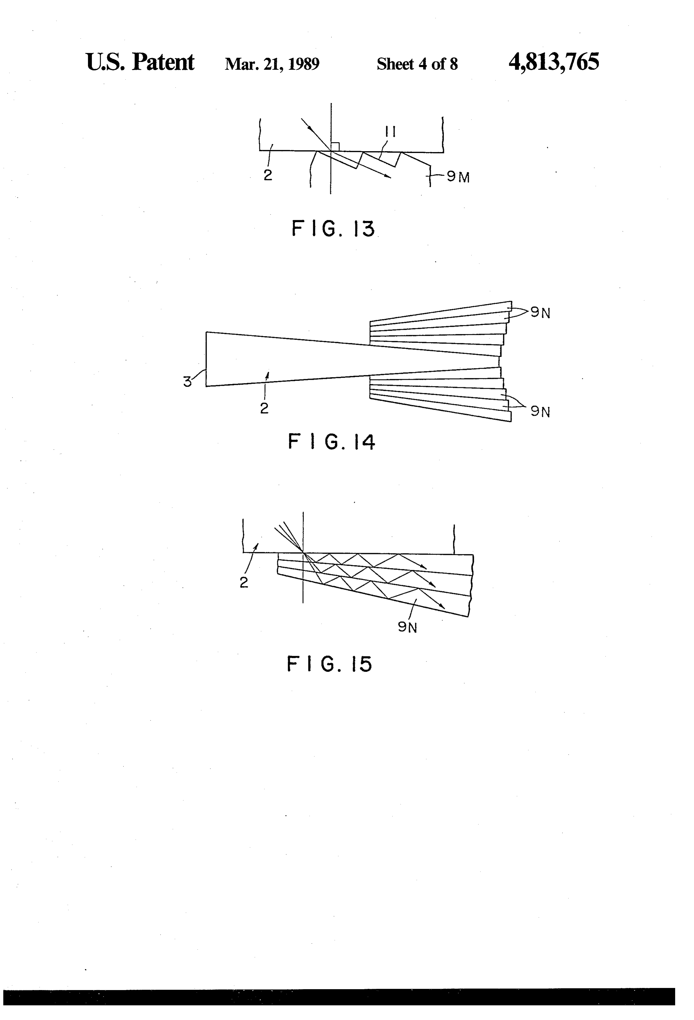
from any directions without the use of a light source FIG. 12 illustrates modified auxiliary elements; tracking device and which can convert them into light rays within a predetermined direction range so as to 35 FIG. 13 is a partial view, on an enlarged scale, of facilitate the utilization of the received light rays. FIG. 12;
FIG. 14 illustrate yet further auxiliary elements;
DISCLOSURE OF THE INVENTION FIG. 15 is a partial view, on an enlarged scale, of A device for changing the directions of light rays in FIG. 14;
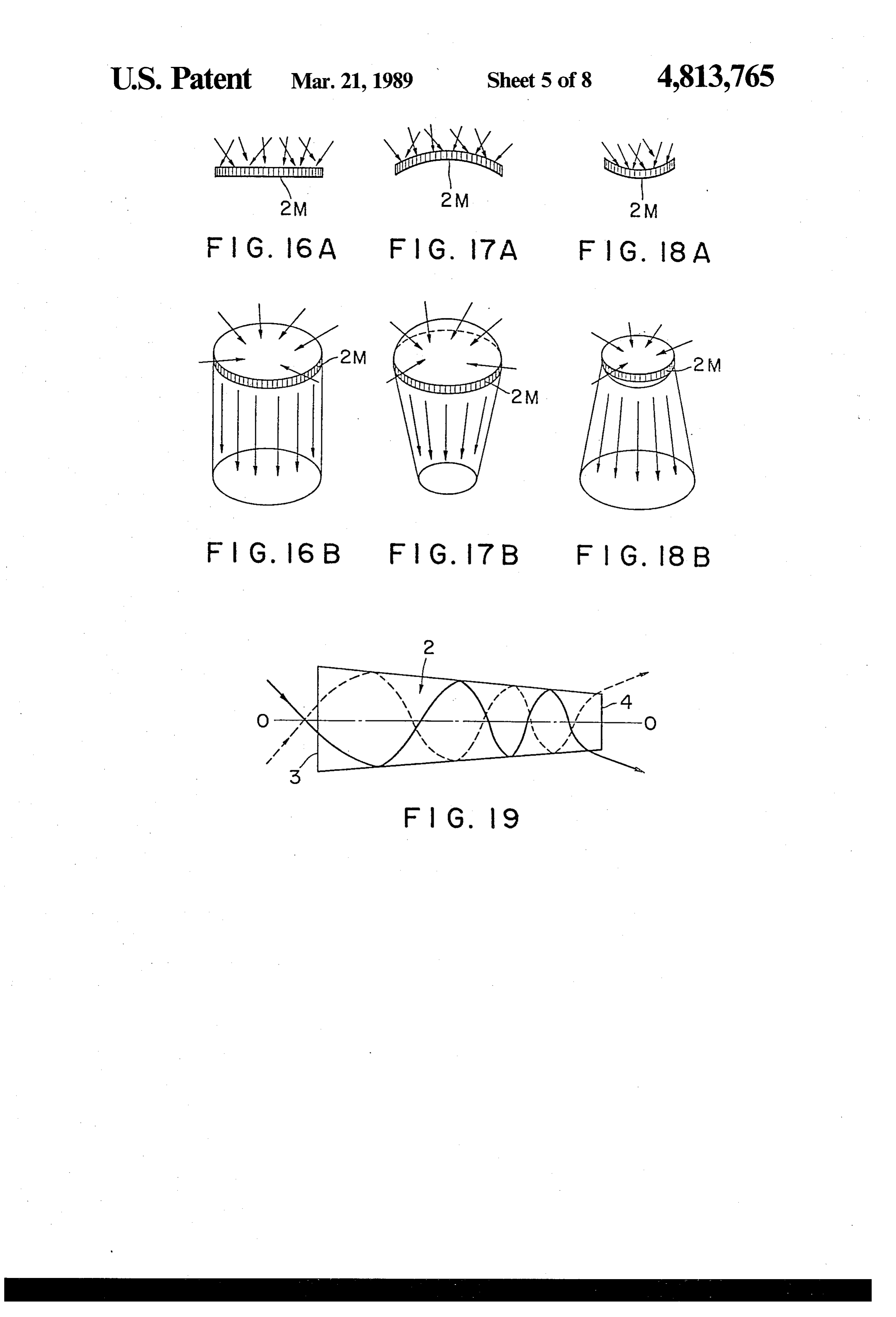
accordance with the present invention has a three-di FIG. 16A is a side view of an assembly for changing mensional body which is made of an optically transpar the directions of light rays in which a plurality of main ent material and has a light incidence surface and a light bodies as shown in FIG. 8 or FIG. 9 are assembled; emerging surface. The main body has reflecting sur FIG. 16B is a perspective view of FIG. 16A; faces for causing repetitive reflections of the light rays FIG. 17A is a side view of a modification of the as which have entered the body through the light inci 45 sembly shown in FIG. 16A;
dence surface. The reflecting surfaces of the main body FIG. 17B is a perspective view of FIG. 17A; are so arranged and shaped that the direction of a light FIG. 18A is a side view of a modification of the as ray which is repeatedly internally reflected within the sembly shown in FIG. 16A;
body is caused to have an angle incident on the reflect FIG. 18B is a perspective view of FIG. 18A; ing surfaces, which gradually approaches a critical 50 FIG. 19 shows yet another preferred embodiment of angle with respect to the reflecting surface. A portion the present invention;
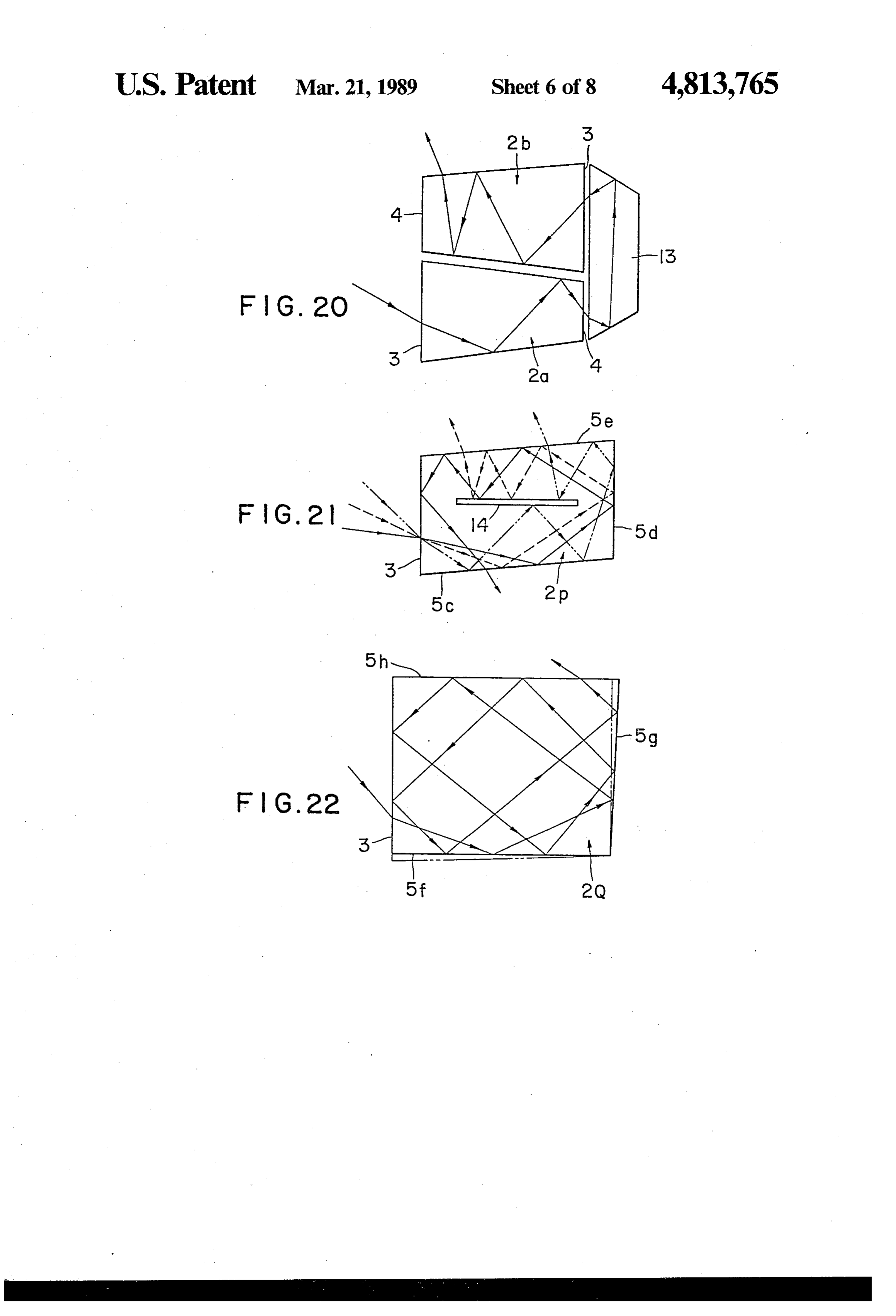
of the main body or a portion adjacent to said first-men FIG. 20 shows an example of a combination of the tioned portion at which the light rays are reflected at main bodies as shown in FIG. 1;
the critical angle or at an angle smaller than the critical FIG. 21 is a view illustrating an embodiment of a angle constitutes the light emerging surface from which 55 "rotation' type device in accordance with the present the light rays whose directions are changed are derived. invention;
The light rays which has entered through the inci FIG. 22 is a view illustrating another embodiment of dence surface of the main body into the same are repeat a "rotation' type device in accordance with the present edly internally reflected and, because of the profiles of invention;
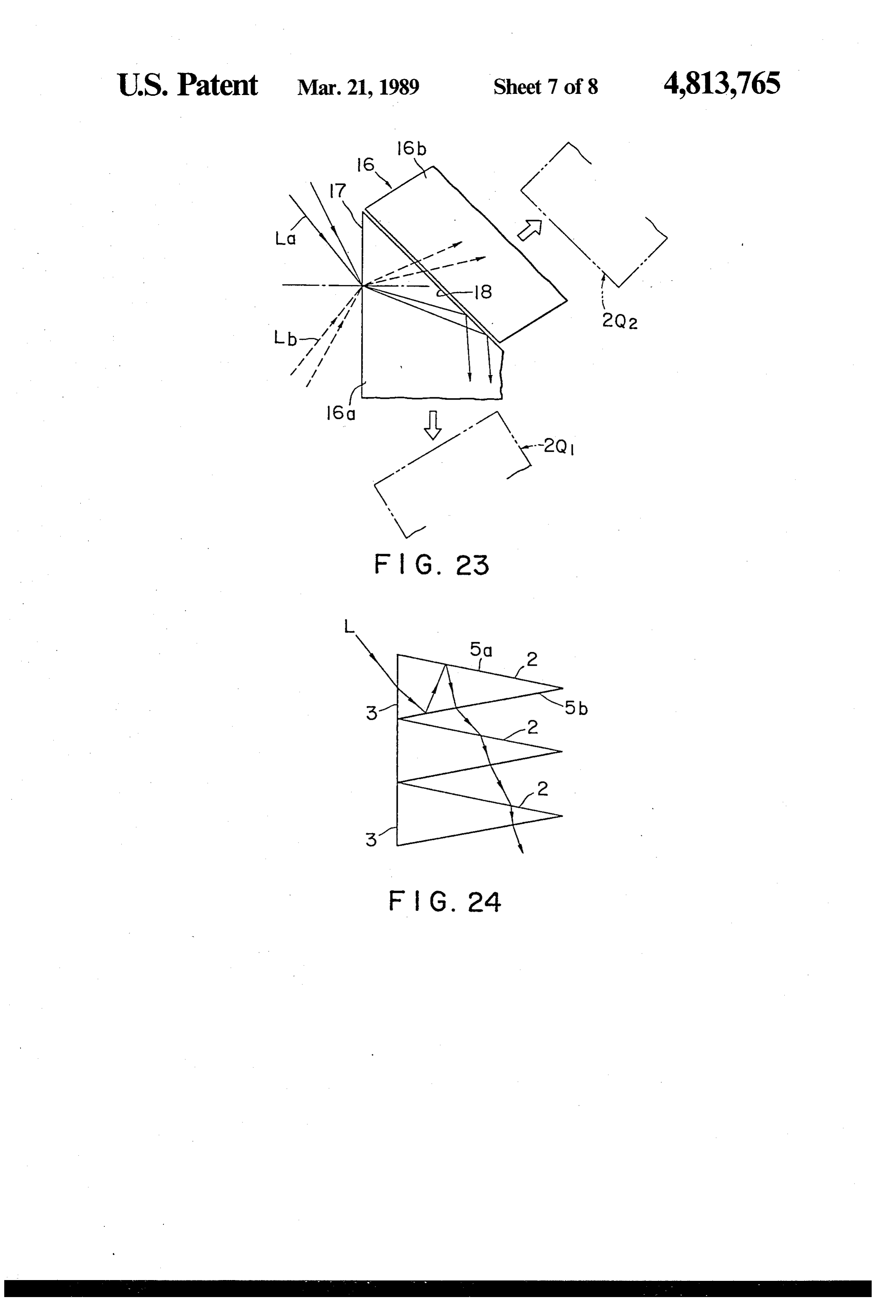
the reflecting surfaces, the angle of each reflected light 60 FIG. 23 is a view illustrating a device for selecting ray relative to a perpendicular is gradually increased the direction of incidence adapted for use with the “ro and becomes equal to the critical angle or an angle tation' type device in accordance with the present in slightly smaller than the critical angle. When reaching vention;
such condition, the light rays are not reflected inter FIG. 24 is a view explanatory of a phenomenon ob nally by the reflecting surface any longer, but refracted 65 served when a plurality of main bodies are assembled at the reflecting surfaces, thus being emitted out of the into a parallel array as shown in FIGS. 4 and 5; main body. Since the light rays are incident to the re FIG. 25 is a sectional view, on an enlarged scale, of a flecting surfaces at angles close to the critical angle, still further embodiment of a device for changing the
Page 11
directions of light rays in accordance with the present When the material of the main body 2 has an index of invention; and refraction n1 and the atmosphere or medium surround FIG. 26 is a sectional view, on an enlarged scale, of a ing the main body 2 has an index of refraction n2, the yet further embodiment of the present invention. following relation is established.
BEST MODES FOR CARRYING OUT THE
INVENTION
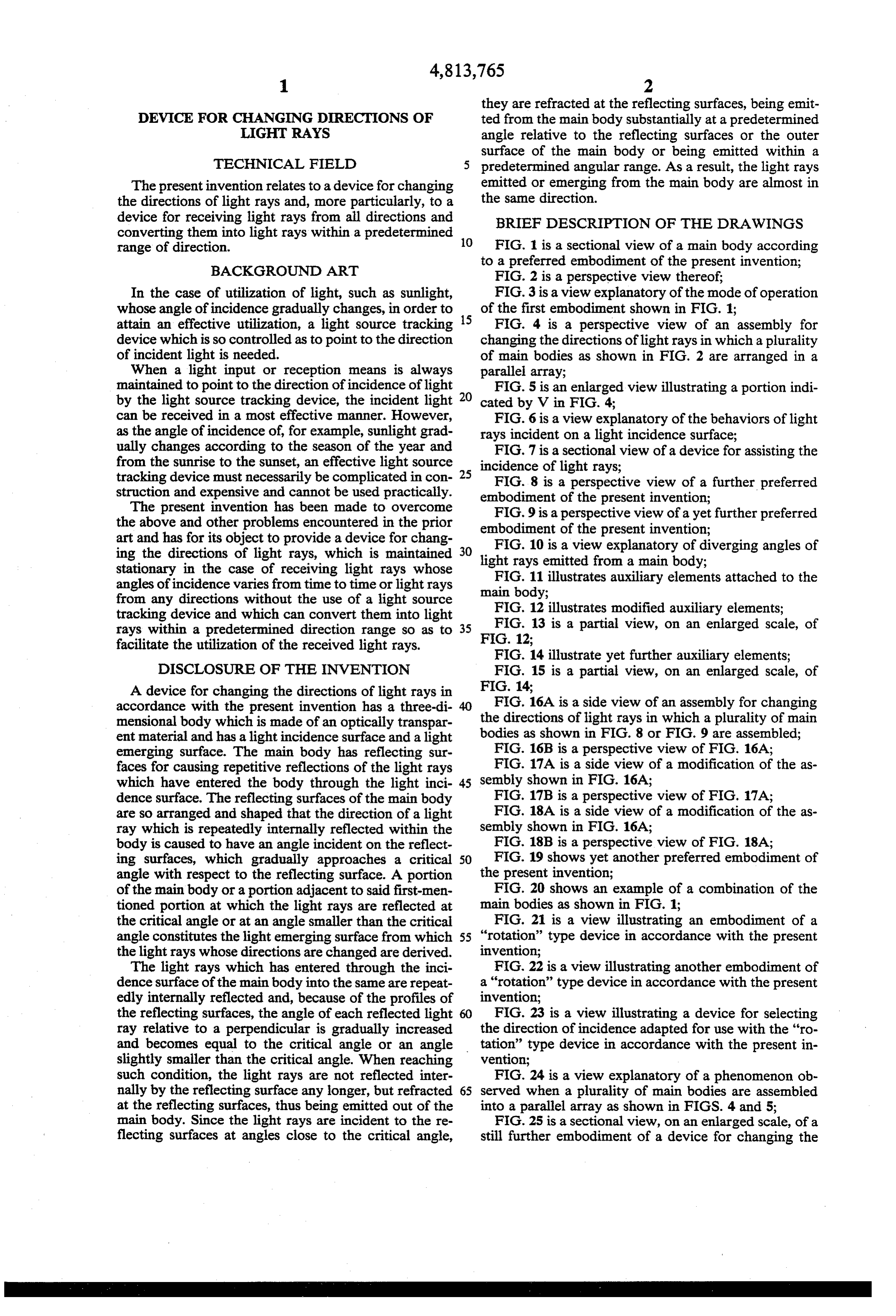
The preferred embodiments of the present invention Meanwhile, whenever a light ray undergoes total will now be described. The device for changing the reflection at the reflecting surface 5a or 5b, the angle of directions of light rays shown in FIG. 1 has a main body O incidence of the totally reflected light ray arriving at 2 made of an optically transparent material such as a the opposite reflecting surface 5b or 5a is decreased by transparent glass, a transparent plastics or the like. The 2a, so that the light ray incident at the reflecting surface main body 2 is, for instance, in the form of a plate of becomes more and more upright relative to the reflect wedge-shaped cross section as shown in FIG. 2 and is ing surface, and when the angle of the light ray becomes gradually decreased in thickness from one side to the 15 smaller than the critical angle 80, at least part of the opposite side. An end surface 3 on one side of the main light ray is refracted at the reflecting surface and emit body 2 defines a light incidence surface, and a pair of ted out of the main body to the surrounding medium. It opposing planes. 5a and 5b which are extended from the follows therefore that if an internal light ray is incident light incidence surface 3 to an end surface 4 on the other at the point Pat an angle smaller than the critical angle side of the main body 2 define reflecting surfaces on 60 by 2a and is refracted totally at the reflecting surface which light rays which have entered the main body 2 and emitted into the surrounding medium as indicated through its light incidence surface 3 are reflected. The by the broken lines in FIG. 3, the following relation is end surface 4 may be made very small in area or elimi established:
nated.
When a light ray L1 is sent to the light incidence 25 n1sin (60-2a)=n2-sin X surface 3 of the main body 2 in the above-described construction shown in FIG. 1, it repeats internal reflec When the surrounding medium is air, n2 = 1 and tions at points a, b, c, d and e on the reflecting surfaces when X=90'-X, the following relation is obtained: 5a and 5b while propagating toward the end surface 4 n1-sin(60-2a)=sin X=sin (TM2-X)-cos X and is finally emitted out of the main body 2 at a point 30 f. In like manner, a light ray L2 incident from a direction Hence, different from the direction of incidence of the light ray
L1 is repeatedly reflected internally at a1, b1, c1, d1 and e1 and is finally emitted out of the main body 2 at a point fl. These internal reflections of the light rays Ll 35 Therefore, when 60-2a.<T/2, the greater the value a, and L2 are total reflection. the greater the value X becomes. Next the above-described phenomenon will be con If the light ray is refracted not totally and emitted out sidered with reference to FIG. 3. It is assumed that the of the main body and the light ray is partly reflected angle between each of the reflecting surfaces 5a and 5b again even when the angle of incidence is smaller than and the center surface (optical axis) O-O of the main the critical angle, the following relation is obtained: body be a and that an internally reflected light ray be incident at a point P on the reflecting surface 5b. When X=cos (n1sin(60-4a):
the angle between the internally reflected incident light ray and a perpendicular to the reflecting surface 5b at As a result, the value X is increased more and more. the point P is greater than a critical angle Öo, the inter 45 As is apparent from the above explanation with refer nally reflected light ray undergoes total reflection at the ence to FIG. 3, the light rays undergo total reflection at point P and is directed again to the opposing reflecting the points a, b, c, d and e and the points a1, b1, c1, d1 surface 5a. On the other hand, when the angle of inci and e1 as shown in FIG. 1 and when the angles of inci dence of the internally reflected light ray incident at the dence of the light rays become equal to or smaller than point P is equal to the critical angle 80, it is refracted 50 the critical angle 8o for the first time at the points f and and emerges parallel to and along the outer surface of f1, respectively, the light rays are refracted and emitted the reflecting surface 5b at the point P. Furthermore, out of the main body 2 to the surrounding medium. The when the angle of incidence of the internally reflected light rays are emitted out of the main body 2 also light ray is smaller than the critical angle 60, it is emitted through its end surface 4 to the surrounding medium. out of the main body 2 into the surrounding medium at 55 When light rays from all directions are incident on an angle X in relation to the perpendicular as indicated the incidence surface 3 and enter the main body 2 and by the broken lines. As described above, the angle of when it is desired that the light rays emitted from within incidence of a light ray striking the reflecting surface is the main body through the reflecting surfaces 5a and 5b small, the light ray is totally reflected at the reflecting and the end surface 4 are in parallel or almost in parallel surface and when the angle of incidence is gradually with the optical axis O-O, it is preferable that the angle decreased and becomes equal to the critical angle, at a is made as small as practicable, but when a is made least part of the light ray is refracted at the reflecting small, the whole length L will be increased (FIG. 2). surface and emitted out of the main body 2 into the In order to overcome this problem, the thickness d of surrounding medium in parallel with the outer surface the light incidence surface 3 (FIG. 2) must be reduced of the reflecting surface. Furthermore, when the angle 65 as much as possible.
of incidence is increased, it is refracted at the reflecting When main bodies 2 having a thickness d made as surface and emitted out of the main body, 2 into the small as possible are utilized, they are arranged in a surrounding medium. parallel array as shown in FIGS. 4 and 5 so that the
Page 12
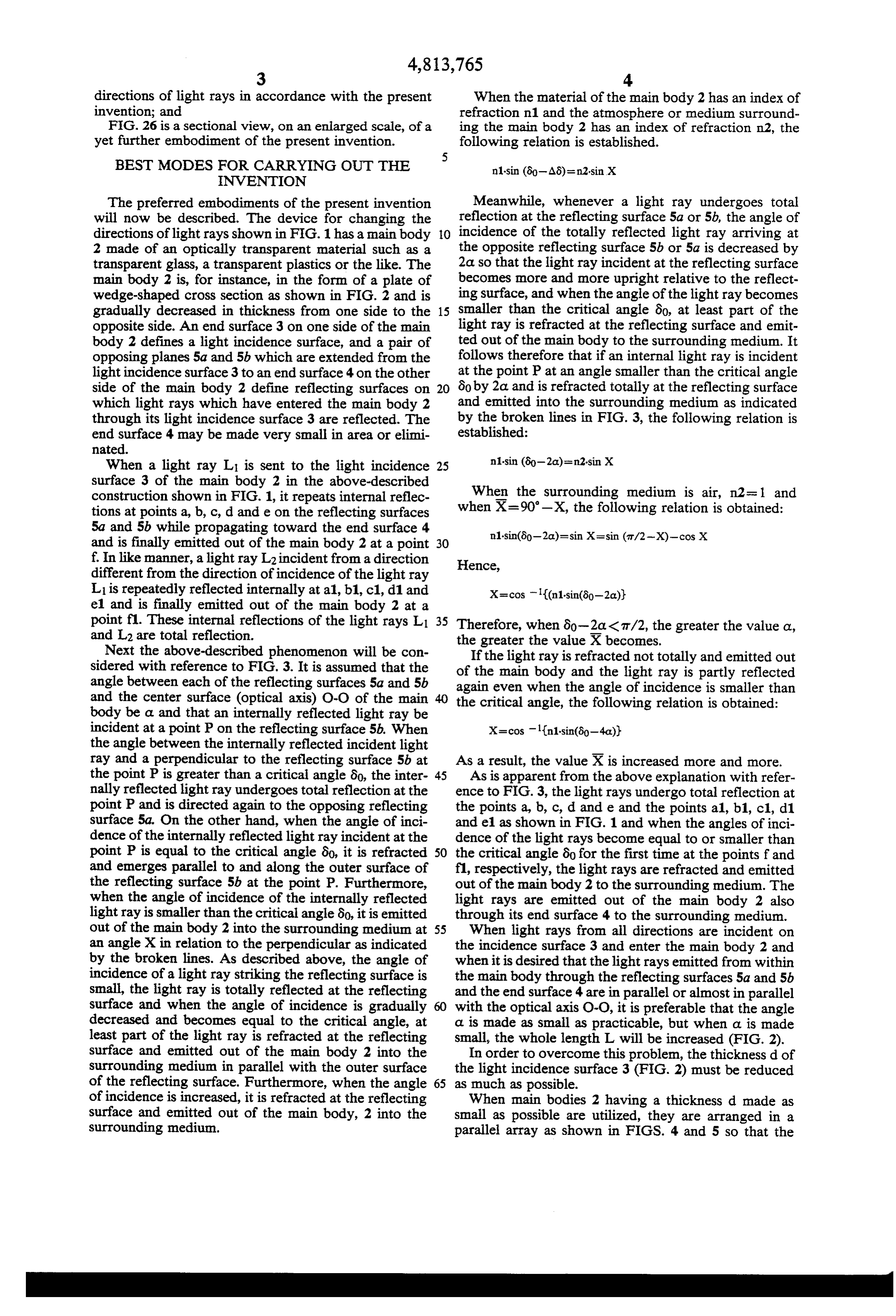
light incidence surfaces of all the main bodies 2 define a elements 9 each having a triangular cross sectional con large surface 3A. Then light rays which are incident on figuration are attached to the outside surface of a light the large surface 3A from all directions are changed in emitting portion of the main body 2. The light rays directions of propagation within the main body and which are emitted from the main body 2 with a wide emitted out of the main body in directions almost per diverging angle pass through thin air layers between the pendicular to the surface 3A. main body 2 and the auxiliary elements 9 and then are Next the input of light rays through the light inci reflected or refracted at least once by the reflecting dence surface 3 into the main body 2 will be considered. surfaces 10 or the auxiliary elements 9 after the light It is assumed that the atmosphere or medium surround rays enter the latter whereby the directions of propaga ing the main body 2 be the air with n2 = 1 and the main 10 tion of light rays are changed to those substantially in body 2 is made of an acrylic resin with n=1.491. Then, parallel with the optical axis when emitted from the
main body 2. To this end, the reflecting surfaces 10 n1sin 60=n2-sin 90 diverged rearwardly in the direction opposite to that of 15 the light incidence surface 3. The reflecting surfaces 10 may be formed of reflecting films which, for instance, 1.491 sin 80=1:sin 90 are fabricated by a vacuum deposition process using aluminum. The auxiliary elements 9 are made of solid
Therefore, material. Instead, only mirrors may be provided at the positions of the reflecting surfaces 10. In the case of 80=sin(sin 90/1491)=42.12' providing the auxiliary elements 9 for the main body 2 Therefore, when viewed at a sectional plane, various of FIG. 2, the elements are in the form of a plate of light rays in air within an angular range of triangular cross section, while for the main bodies 2M, 80x2=84.24 can enter the main body 2 and are trans 2N of FIGS. 8 and 9, they take the form of an annulus mitted therethrough by reflections at the reflecting 25 encircling the main body.
Auxiliary elements 9M shown in FIG. 12 are different surfaces 5a and 5b.
FIG. 7 shows a device for assisting the input of light from those shown in FIG. 11 in that the surfaces of the rays into the main body 2 of the device for changing the auxiliary with the elements 9M which are made into contact main body 2 are formed with sawtooth por directions of light rays. This device serves to reduce the 30 quantity of said material of the main body 2 as much as tions 11. An air layer is formed between the sawtooth possible so that the device for changing the directions of portion 11 and the main body 2, whereby, as shown on light rays can be made light in weight and fabricated an enlarged scale in FIG. 13, the light rays which are economically. The device comprises mirrors 7 extended emitted out of the main body 2 into the air layer include from the opposite sides of the light incidence surface 3 increased components in parallel with the optical axis. in such a way that they converge toward the incidence 35 Therefore, in order to fully utilize such components, the surface 3. Incident light rays from various directions are sawtooth surfaces of the auxiliary element 9 receive the reflected by the inner surfaces of the mirrors 7 and light rays emitted from the main body 2 substantially at directed to the incidence surface 3. right angles therewith or in the directions almost paral As described above, the reflecting surfaces. 5a and 5b lel with the optical axis. When the light rays are emitted are converged gradually in the direction away from the out of the auxiliary element 9M, its components parallel light incidence surface 3, but it is to be understood that with the optical axis are increased. the reflecting surfaces need not be opposing flat reflect In an embodiment as shown in FIG. 14, an auxiliary ing surfaces. element 9N consists of a lamination of a plurality of In an embodiment shown in FIG. 8, a circular light relatively thin layers. Each layer of the auxiliary ele incidence surface 3M is merged with a conical reflect 45 ment is gradually increased in thickness in the direction ing surface 5M so that a main body 2M is in the form of away from the incidence surface 3 whereby, as shown a frustum of cone. in FIG. 15, components of the light rays which are in In an embodiment as shown in FIG. 9, a main body parallel with the optical axis are gradually increased as 2N is in the form of a hexagonal prism and the reflecting the light is transmitted through the layer by reflections surfaces 5N are defined by the inclined surfaces of the SO and emitted out of the layer to the surrounding medium. hexagonal prism. In addition, any prism having any Unlike the main body as shown in FIG. 2, especially cross sectional configuration may be used. the prism-shaped device for changing the directions of In both of the embodiments shown in FIGS. 8 and 9, a light ray enters through the light incidence surfaces light the rays shown in FIGS. 8 or 9 is adapted to receive light rays from all arbitrary directions around the 3M and 3N and undergoes repeated total internal reflec 55 tions in a manner substantially similar to that described whole circumference and to change the directions of the light rays thus taken in. A plurality of such main hereinbefore with reference to FIG. 1 and is emitted out of the main bodies 2M and 2N. In this case, it should be bodies can be also arranged or assembled into an array noted that a light ray propagates along a three-dimen so that they may be utilized in a mode substantially sional path. similar to that described above with reference to FIG. In the above-described embodiments, the light rays 4.
which undergo successive total reflections inside the Such an embodiment is shown in FIGS. 16A and 16B. main body 2, 2M or 2N are emitted out of the main body A plurality of main bodies 2M (2N) are bundled or with a diverging angle gas shown in FIG. 10 so that the assembled in the form of a circular disk as shown in quantity of light rays in parallel with the optical axis is 65 FIG. 16A or in any suitable shape. Innumerable light not so great. rays from all directions are rendered substantially paral In order to overcome this problem, in an embodiment lel with each other as shown in FIG. 16B by this assem as shown in FIG. 11, optically transparent auxiliary bly.
Page 13
In the case of the embodiment shown in FIGS. 16A cated by the solid line and redirected toward the main and 16B, the surfaces of light incidence of the main body 2C1, but the light rays indicated by the broken bodies 2Mare arranged in coplanar relationship, but it is lines pass through the inclined surface 18 toward the also possible that they may be arranged to define a second main body 2C2. As described above, the light convex surface as shown in FIGS. 17A and 17B or rays incident on the surface 17 of incidence at various alternatively to define a concave surface as shown in angles of incidence are so selected by the selector as FIGS. 18A and 18B. In the case of the former, the light light rays propagating in one direction and the light rays emitted from the main bodies converge while in the rays propagating in another direction whereby the main case of the latter the light rays emitted from the main bodies of the embodiments shown in FIGS. 21 and 22 bodies diverge. In these cases, the light rays confined in 10 are utilized to change the directions of propagation of a solid angle in corelation with the concave or convex light rays from any arbitrary directions. surface are projected. The total reflection surfaces of the main body can be In an embodiment shown in FIG. 19, the index of coated with a reflecting film except at a portion through refraction of the main body 2 is gradually or stepwise which the light rays are emitted out of the main body to decreased away from the optical axis O-O toward the 15 the surrounding medium.
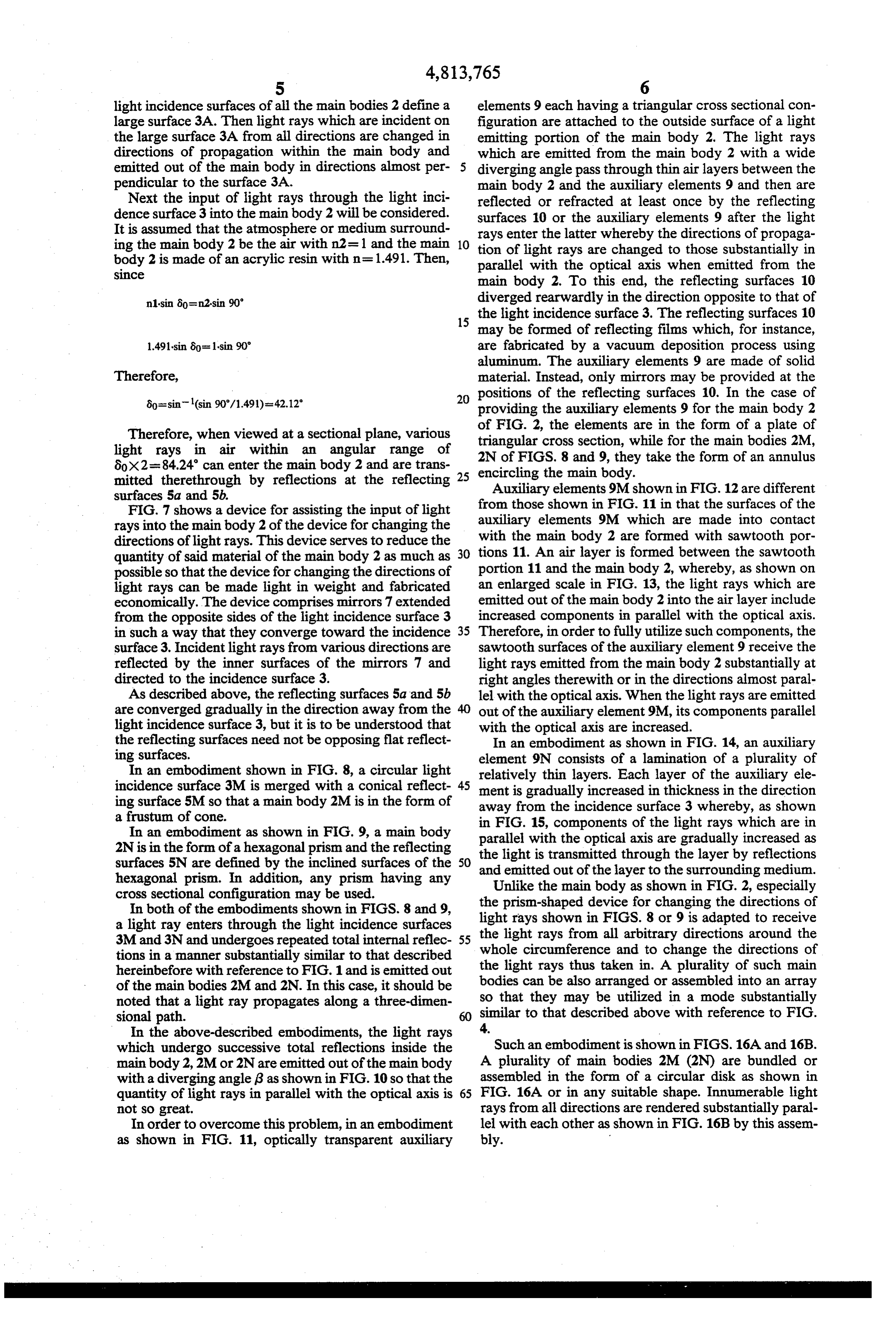
outer surface. As a result, the path of a light ray which FIG. 24 is a diagrammatic view illustrating on a fur is repeatedly reflected and transmitted through the main ther enlarged scale a portion of the assembly in which a body becomes non-linear. plurality of main bodies 2 are arranged in a parallel In an embodiment as shown in FIG. 20, two main array as shown in FIGS. 4 and 5. As described above, bodies 2a and 2b are arranged in opposite directions and when a transparent connecting element 13 is mounted on the dence ainto light ray enters through the surface 3 of inci any one of the main bodies 2, it undergoes end surface 4 of the first main body 2 and the surface 3 repeated total reflections within the main body 2 and of incidence of the second main body 2b. Therefore, the then is emitted out of the main body 2 into the surround light rays emitted from the first main body 2a enter the ing medium. As described connecting element 13, are reflected in the interior of L is converted into a lightabove, 25 the incident light ray ray which is emitted out of the same, and then enter the second main body 2b. the main body and has an increased components parallel Thus, in this embodiment, the light rays are reversed in to the longitudinal direction of the main body relative to direction when being emitted to outside.
Unlike the embodiments described above, in an em the incident light ray L. When the light rays emitted out bodiment shown in FIG. 21, a main body 2P has a sur 30 of the one main body 2 enters the adjacent main body 2 face of light incidence 3 and reflecting surfaces 5c, 5d successively, the components parallel to the longitudi and 5e and the surface of incidence 3 also serves as a nal direction of the main body 2 are gradually decreased reflecting surface. The main body 2P has a rectangular as shown in FIG. 24 as it passes through one main body cross sectional configuration as a whole and a reflecting to another. It is therefore quite apparent that such phe plate 14 is embedded in the main body 2P. Therefore, a 35 nomenon is not desirable.
light ray which enters through the surface of incidence In order to prevent such undesired phenomenon, the 3 into the main body 2P undergoes "rotating” reflec assembly as shown in FIG. 25 can be used. According tions by the reflecting surfaces 5c, 5d and 5e, the surface to this assembly, a plurality of main bodies 2d which are of incidence 3 and the reflecting plate 14 and is emitted arranged in a parallel array and directed in one direc out of the main body 2P to the surrounding medium tion are inserted into the spaces defined between the when the light ray reaches one of the reflecting surfaces adjacent main bodies 2c which are arranged in a parallel at an angle of incidence smaller than a critical angle Öo. array and directed in the other or opposite direction in In an embodiment shown in FIG. 22, a main body 20 complementary relationship. In this assembly, a light has a pair of opposing non-parallel reflecting surfaces 5f ray L, which is incident on the surface 3 of incidence of and 5h and also a pair of opposing non-parallel reflect 45 one main body 2c and enters the same, undergoes re ing surfaces 3 and 5g. A light ray which enters through peated total reflections within the main body 2c, is emit the surface 3 of incidence into the main body 2C, there ted out from the main body 2c and immediately enters fore, undergoes rotating reflections successively and is an adjacent main body 2d which is oriented in the one emitted out of the main body 20 into the surrounding direction. After undergoing repeated total reflections medium when the light ray reaches one of the reflecting 50 within the main body 2d, the light is emitted out of the surfaces at an angle of incidence smaller than a critical main body 3d into the surrounding medium through the angle 8o as shown. bottom surface of the main body 2d. Thus, the phenom In the cases of the embodiments shown in FIGS. 21 enon described before with reference to FIG. 24 can be and 22, the surface 3 of incidence premits a light ray at avoided.
a predetermined angle of inclination with respect 55 In the case of the assembly of the main bodies 2c and thereto to enter the main body and the reflection of the 2d as shown in FIG. 25, a suitable light control element light ray which has thus entered is reflected in a prede can be attached to at least one surface of the assembly. termined direction of "rotation' so that no such effect is In the case of an embodiment illustrating such attach attained when a light ray is reflected and rotated in the ment of optical control elements, as shown in FIG. 26, opposite direction. A device for selecting the angles of 60 a lenticular lens 20 is attached to the surfaces 3 of inci incidence as shown in FIG. 23 can be used in conjunc dence of the main bodies 2c. Further, a Fresnel lens 21 tion with the above-described main body. The device is attached to the bottom surfaces of the main bodies 2d. for selecting the angles of incidence (to be referred to as It is possible to exchange the positions of such lenticular "a selector' for brevity in this specification) comprises lens and Fresnel lens or to eliminate a lenticular lens or a first transparent element 16a and a second transparent 65 Fresnel lens. Furthermore, it is possible to superimpose element 16b. A light ray incident at an arbitrary angle of a plurality of such light control elements one upon incidence on a surface 17 of incidence of the first ele another. Moreover, other light control elements can be ment 16a is reflected by an inclined surface 18 as indi used. When such light control elements are provided,
Page 14
further controls of light rays in response to optical char a light incidence surface interconnecting one end acteristics of these light control elements can be made. of said reflecting surfaces, said reflecting surfaces As described above, when the device for changing converging gradually in a direction away from said the directions of light rays in accordance with the pres light incidence surface; ent invention is utilized, light rays from different direc causing light rays having various directions to enter tions and within a certain angular range, incident on a said optical body through said light incidence sur stationary surface of incidence, can be caught and can face;
subject them to repeated internal reflections there causing the light rays, which have entered said opti within, to convert the light rays into light rays which cal body, to be internally and successively reflected are substantially in parallel with a desired direction. 10 by said reflecting surfaces until said successively Furthermore, even when the direction of incident light internally reflected light rays are caused to have varies, it is not needed to trail the incident light. More angles incident on the reflecting surfaces, which over, the three-dimensional main body used in this in angles are equal to or smaller than a critical angle vention can be fabricated from a simple optically trans with respect to said reflecting surfaces; and parent material. Therefore, the device, in accordance 15 causing the light rays, whose angles incident on the with the present invention is inexpensive and is free reflecting surfaces have become an angle equal to from breakdowns. In addition, in the device in accor or smaller than said critical angle, to emerge from dance with the present invention, a plurality of main within the optical body to the outside through a bodies can be assembled into various shapes to obtain light emerging surface portion of the optical body further useful effects. When the devices in accordance 20 remote from said light incidence surface, in such a with the present invention are superimposed one upon manner that the light rays emerging will be within another or bundled, further complex and useful effects a limited range of directions; and can be obtained. causing the light rays emerging from said light
INDUSTRIAL APPLICABILITY
emerging surface portion to pass through transpar 25 ent auxiliary elements of substantially triangular
According to the present invention, it becomes possi cross section, disposed outside of and adjacent to ble to receive scattered light, diffused light, light emit said light emerging surface portion, so as to make ted from various portions of a light source having some smaller the range of directions of the light rays size, light whose direction varies and so on to redirect it which have passed through the auxiliary elements. in a predetermined direction or project it with a desired 30 2. A method as set forth in claim 1, further compris shape. Therefore, the present invention can be used for ing the step of directing light rays having various direc utilization of the solar energy, illumination control, tions to said light incidence surface by means of a mirror transmission of images and patterns and so on. disposed adjacent to the light incidence surface. I claim: 3. A method as set forth in claim 1, further compris 1. A method of converting rays having various direc 35 ing the step of causing the light rays emerging from the tions into light rays within a limited range of directions light emerging surface to pass through air gaps formed comprising the steps of: between the light emerging surface and the auxiliary providing a transparent optical body in the form of a elements before the light rays are passed through the wedge-shaped plate having opposite non-parallel auxiliary elements. s major surfaces constituting reflecting surfaces, and 40 s
Provenance
- Collection
- Cited prior art
- Original PDF
- patentimages.storage.googleapis.com →
- Filed
- 1986-09-19
- Pages
- 14
- Method
- pdftotext (the PDF's own text layer) + pdftoppm 300dpi page scans
- Source
- Google Patents bibliographic record
- Granted
- 1989-03-21
- Inventors
- Masataka Negishi
- Transcribed from
- patentimages.storage.googleapis.com →