patent · US4922107
Apparatus emitting an electromagnetic radiation, in particular infrared, comprising a plane source of rays and a reflector
1 May 1990
Page 1 — bibliographic record
United States Patent (19) 11 Patent Number: 4,922,107 Rablet al. 45 Date of Patent: May 1, 1990 54 APPARATUS EMITTING AN 4,066,887 3/1978 Levis ................................ 30/30 H ELECTROMAGNETIC RADIATION, IN 4,114,592 9/1978 Winston .............................. 350/628 PARTICULAR INFRARED, COMPRISING A 4,129,115 i2/1978 Wyatt.................................. 350/628 PLANE SOURCE OF RAYS AND A 4,130, 107 12/1978 Rablet al. ........................... 350/628
REFLECTOR 4,596,935 6/1986 Lumpp ............................ 250/504 R (75) Inventors: Ari Rabl, Montgeron; Denis Clodic, FOREIGN PATENT DOCUMENTS Paris; Robert Dehausse, Joinville le
Pont, all of France 1110073 4/1968 United Kingdom .
(73) Assignee: A.R.M.I.N.E.S., Paris, France Primary Examiner-Jack I. Berman Attorney, Agent, or Firm-McAulay Fisher Nissen & (21) Appl. No.: 275,002 Goldberg (22 Filed: Nov. 22, 1988 (57) ABSTRACT 30 Foreign Application Priority Data This invention relates to an apparatus emitting infrared Nov. 25, 1987 FR France ................................ 87 16361 radiation which comprises a plane source of infrared rays and a reflector. In order to avoid the problem due 51) Int. Cl. ................................................. F21J 7/12 to captive rays and to multiple reflections, the cross 52 U.S. C. ............................. 250/504 R; 250/505.1; section of each half-reflector located on one side of the 250/493.1; 350/628; 350/630 plane of symmetry has the form of an arc of ellipse 58) Field of Search ............ 250/493.1, 504 R, 504 H, whose two foci are respectively constituted by the first 250/494.1,495.1, 505.1; 350/628, 630 end of the plane source and the first end of the target (56) References Cited which are both located on the other side of the plane of
Re. 17,038 7/1928 Ballman ................................ 353/98 second end of the plane source and the point of intersec 3,449,561 6/1969 Basil ............... ... 362/350 tion of the ellipse with the direct ray going from the first 3,827,059 7/1974 Rambauske ... ... 350/620 end of the plane source to the second end of the target. 3,923,381 12/1975 Winston ......... ... 350/628 4,003,638 1/1977 Winston .............................. 350/628 9 Claims, 1 Drawing Sheet
Page 2
Drawing sheet — no readable text.
Page 3
BRIEF DESCRIPTION OF THE DRAWINGS
APPARATUS EMITTING AN
ELECTROMAGNETIC RADIATION, IN The invention will be more readily understood on PARTICULAR INFRARED, COMPRISING A reading the following description with reference to the PLANE SOURCE OF RAYS AND A REFLECTOR 5 accompanying drawings, in which:
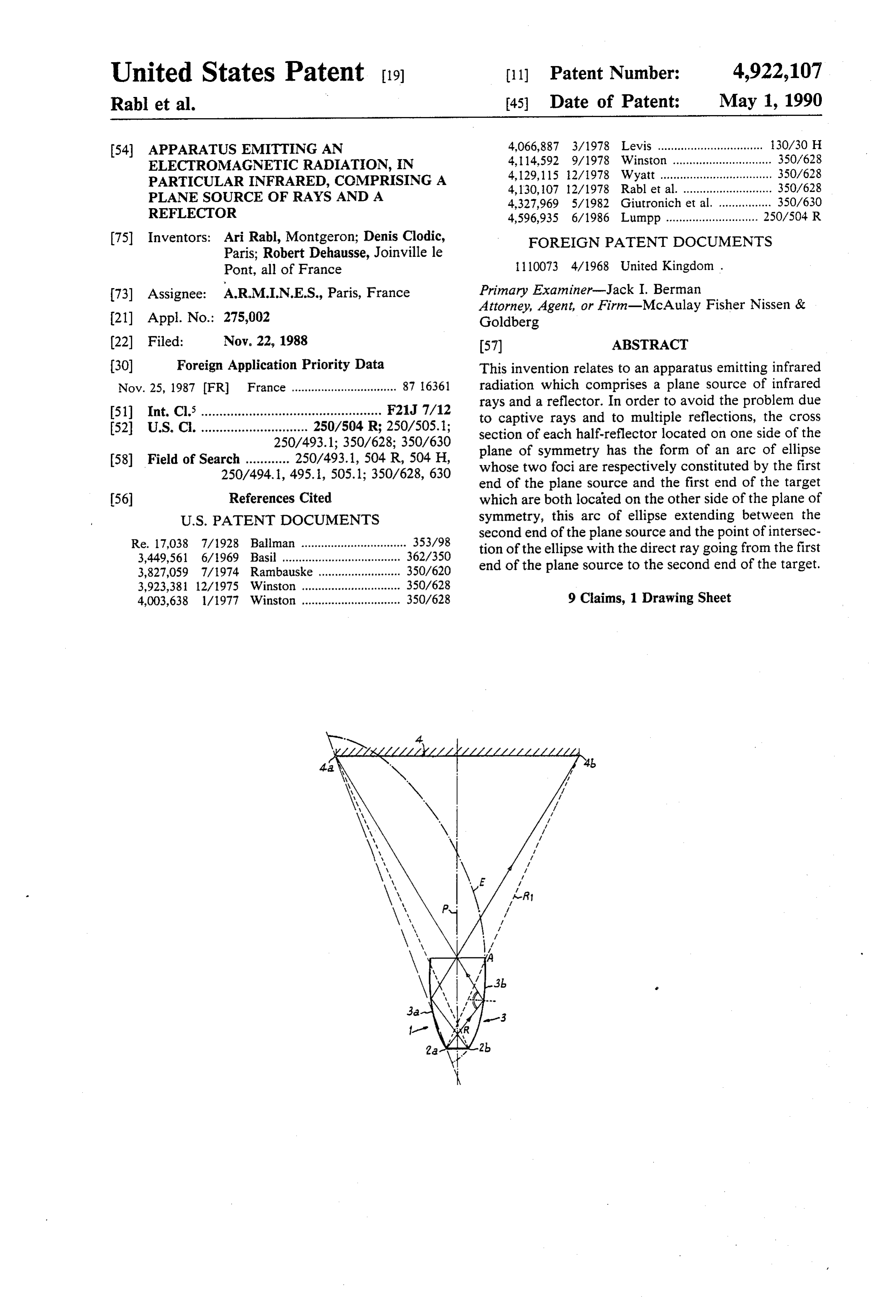
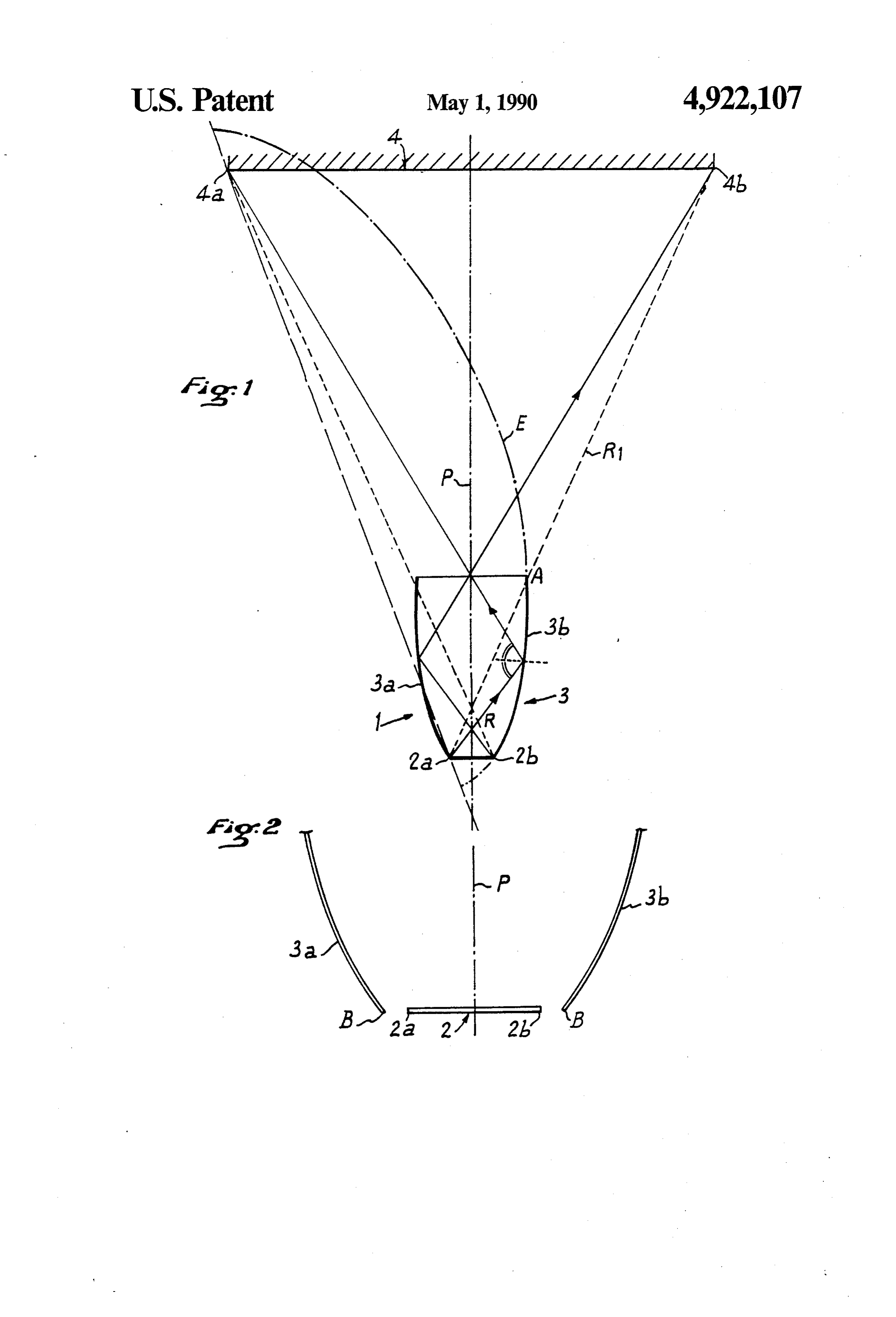
FIG. 1 is a diagram of an apparatus according to the
FIELD OF THE INVENTION invention for emitting infrared radiation. FIG. 2 is a diagram of a variant embodiment.
The present invention relates to an apparatus emitting an electromagnetic radiation, in particular infrared, O DETAILED DESCRIPTION OF THE comprising a plane source of rays and a reflector. DRAWINGS BACKGROUND OF THE INVENTION Referring now to the drawings, the apparatus accord ing to the invention for emitting radiation is generally
In an apparatus emitting electromagnetic radiation, designated by reference 1 in FIG. 1. This apparatus may particularly infrared, the reflector must be shaped and 15 emit any type of electromagnetic radiation, particularly mounted, with respect to the source of rays, so that light or infrared. However, in the following description. there are no rays captive between the source of rays and the apparatus will be considered, by way of non-limit the reflector. In fact, such captive rays are the cause of ing example, as emitting an infrared radiation. This a loss of yield and of local excess heating. In addition, apparatus comprises a plane source of infrared rays 2, the shape and arrangement of the reflector must enable 20 constituting a rectangular radiant panel, which is per it to eliminate the multiple reflections between source pendicular to a plane P which constitutes a plane of symmetry for the whole of apparatus 1, this plane P and reflector, which are naturally detrimental to the being perpendicular to the sheet of the drawing. The yield obtained with the apparatus. plane source 2 is defined as extending between two ends Radiation, and particularly light radiation emitting 2a and 2b which apparatus are already known, as described for example respect to plane P. are symmetrical to each other with in U.S. Pat. No. Re. 17,038, U.S. Pat. No. 4,066,887 and ratus also comprises a infrared
The reflector radiation emitting appa 3 which is adapted to
GB-A-No. 1 110 073. In the first two documents, the source of radiation is punctual and it is associated with which, for simplification purposes, is2 onto return the rays emitted by the source a target 4 considered as a reflector which is generally in the form of a parabo 30 being a plane in FIG. 1 and extending perpendicularly loid. Patent GB-A-No. 1 110 073 relates to a reflector to the plane of symmetry P of the emitter apparatus 1. for a rectilinear infrared ray source, whose half cross This target 4 extends between two ends 4a, 4b, symmet section comprises two arcs of parabola joined together rical to one another with respect to plane P, the first end by an arc of circle centred on the source of the rays. 4a being located, with respect to plane P, towards the However, the solutions adopted in all these known 35 first end 2a of the source 2, whilst the second end 4b of apparatus in no way avoid the above-mentioned prob the target 4 lies on the opposite side, in the same way as lems when the source of radiation is plane. the second end 2b of source 2. The present invention relates to an apparatus which The reflector 3 is constituted by two cylindrical makes it possible to satisfy these conditions and to ob halves symmetrical with respect to plane P. namely a tain a particularly high yield, with a remarkably simple 40 left half3a and a right half 3b. Each half reflector has a Structure. cross section which is constituted, in the case of the
SUMMARY OF THE INVENTION
right-hand half-reflector 3b, by an arc of an ellipse E having for foci the first ends 2a of the plane source 2
To that end, this apparatus emitting an electromag and 4a of the target 4 and passing through the second netic radiation, particularly infrared, comprising a plane 45 end 2b of the plane source 2. The right-hand half-reflec source of rays and a reflector for reflecting these rays tor 3b extends between the second end 2b of the plane emitted in the direction of a target defined as extending source 2 and a point A located at the intersection of the between two ends, the source, the reflector and the ellipse E and the extreme direct ray R1 which extends target being symmetrical with respect to the same plane between the first end 2a of the plane source and the of symmetry of the emitter apparatus, so that the reflec 50 second end 4b of the target 4. Thanks to the particular shape of the cross section of tor is constituted by two halves of the same cross sec each half3a, 3b of the reflector 3, each ray issuing from tion located on either side of the plane of symmetry and that the plane source, perpendicular to the plane of any point of the plane source 2 is reflected by the reflec symmetry, comprises first and second ends located on 55 atormultiple 3 in the direction of the target 4 without there being reflection of any rays or a ray captive be- .
either side of this plane, is characterized in that the cross tween the source 2 and the reflector 3. For example, section of each half-reflector, located on one side of the plane of symmetry, has the form of an arc of ellipse of 2a or left-hand endtheofrays
FIG. 1 shows that R issuing from the first end the source 2 directly attain the which the two foci are constituted respectively by the target 4 or are reflected by the right-hand half-reflector first end of the plane source and the first end of the 60 3b, in the direction of the first end 4a of the target 4, target which are both located on the other side of the without being intercepted by the left-hand half-reflector plane of symmetry, this arc of ellipse extending between 3b. The same applies, of course, for all the rays issuing the second end of the plane source located on the first from the second end or right-hand end 2b of the source side of the plane of symmetry or a point located in the 2, which directly attain the target 4 or are reflected by immediate proximity of this second end and the point of 65 the left-hand half-reflector 3b in the direction of the intersection of the ellipse with the direct ray going from right-hand end of the target 4. the first end of the plane source to the second end of the In the variant embodiment of the invention shown in target. FIG. 2, the two half-reflectors 3a and 3b are not joined
Page 4
directly to the two ends 2a, 2b of the source 2 and they the plane of symmetry or a point located in the terminate at points B which are located at a short dis immediate proximity of this second end and the tance from ends 2a, 2b of the source 2. In this way, point of intersection of the ellipse with the direct openings are determined between the ends 2a, 2b of the ray going from the first end of the plane source to source 2 and points B, which allow admission of air to 5 a second end of the target. ensure internal cooling of the apparatus 1. 2. In the apparatus as claimed in claim 1, wherein said The radiation emitter apparatus according to the reflector includes a left half reflector and a right half invention may be used in the whole visible and invisible reflector.
spectrum and it may in particular constitute a light 3. In the apparatus as claimed in claim 2, wherein said beam projector, mounted, for example, on an automo 10 left half reflector and said right half reflector are free of bile vehicle. any connection with said source. What is claimed is: 4. In the apparatus as claimed in claim 2, wherein 1. In an apparatus emitting infrared radiation, com each of said left half reflector and said right half reflec prising a plane source of infrared rays and a reflector for tor is spaced from an end of said plane source to define reflecting these infrared rays emitting in the direction of 15 an opening between said left half reflector and said a target defined as extending between two ends, the plane source and said right half reflector and said plane source, the reflector and the target being symmetrical source for allowing admission of air to the apparatus to with respect to the same plane of symmetry of the emit ensure internal cooling thereof. ter apparatus, so that the reflector is constituted by two 20 5. In the apparatus as claimed in claim 2, wherein said halves of the same cross section located on either side of the plane of symmetry and that the plane source, per nected left half reflector and said right half reflector are con pendicular to the plane of symmetry, comprises first and with said plane source. second ends located on either side of this plane, 6. In the apparatus as claimed in claim 1, wherein said the cross section of each half-reflector, located on plane source is a rectangular radiant panel. one side of the plane of symmetry, has the form of 25 7. In the apparatus as claimed in claim 4, wherein said an arc of ellipse of which the two foci are consti plane source is a rectangular radiant panel. tuted respectively by the first end of the plane 8. In the apparatus as claimed in claim 5, wherein said source and a first end of the target which are both plane source is a rectangular radiant panel. located on the other side of the plane of symmetry, 9. In the apparatus as claimed in claim 2, wherein said this arc of ellipse extending between the second 30 plane source is a rectangular
radiant panel.
end of the plane source located on the first side of
Provenance
- Collection
- Cited prior art
- Original PDF
- patentimages.storage.googleapis.com →
- Filed
- 1988-11-22
- Pages
- 4
- Method
- pdftotext (the PDF's own text layer) + pdftoppm 300dpi page scans
- Source
- Google Patents bibliographic record
- Granted
- 1990-05-01
- Inventors
- Ari Rabl; Denis Clodic; Robert Dehausse; A R M I N E S
- Transcribed from
- patentimages.storage.googleapis.com →