patent · US4815816A
Image transportation device using incoherent fiber optics bundles and method of using same
28 March 1989
Page 1 — bibliographic record
United States Patent (19) 11 Patent Number: 4,815,816 Schneider (45) Date of Patent: Mar. 28, 1989 54 MAGE TRANSPORTATION DEVICE USNG 4,275,950 6/1981 Meyer .............................. 350/96.10 INCOHERENT FIBER OPTICS BUNDLES 4,332,439 6/1982 Lubbers et al. ..................... 350/320 AND METHOD OF USING SAME 4,570,063 2/1986 De Bie et al. ... 250/227 4,674,834 6/1987 Margolin ...... 350/96.25 75 Inventor: Richard T. Schneider, Alachua, Fla. 4,702,552 iO/1987 Margolin ...... ... 350/96.25 4,738,510 4/1988 Sansom ............................ 350/96.25 (73) Assignee: RTS Laboratories, Inc., Alachua, 4,760,421 7/1988 Margolin ...... ... 350/96.25 X Fla. 4,762,391 8/1988 Margolin .......................... 350/96.25 21 Appl. No.: 48,815 FOREIGN PATENT DOCUMENTS 22 Filed: May 12, 1987 3226015 1/1984 Fed. Rep. of Germany ... 350/96.25 153323 6/1968 France . ... 350/340 (51) Int. Cl* ........................... G02B6/06; H01J 5/16; 58-100813 6/1983 Japan ................................... 350/340
52 U.S. Cl. .............................. 350/96.25; 350/96.24; Primary Examiner-William L. Sikes 350/320; 350/96.18; 350/507; 350/540; Assistant Examiner-Brian M. Healy 350/96.26; 250/227; 128/4; 128/6 Attorney, Agent, or Firm-Foley & Lardner, Schwartz, (58 Field of Search ............... 350/96.10, 96.18, 96.24, Jeffery, Schwaab, Mack, Blumenthal & Evans 350/96.25, 96.26, 320, 507,540; 128/4, 6; 57 ABSTRACT
References Cited The invention includes a fiber optic bundle comprising 56 a plurality of individually optic fiber elements. Each of
2,992,587 7/1961 Hicks, Jr. et al. ................ 350/96.25 The first ends of the optic fiber elements have a smaller 3,128,167 4/1964 Woodcock ....... 350/96.25 X cross-sectional area than the second ends. The first ends 3,464,330 9/1969 Lewis ........... ... 350/96.24 are mechanically joined to provide strength to said fiber 3,512,861 5/1970 Schackert ......................... 350/96.25 optic bundle, Detectors are connected to the second 3,556,085 1/1971 Takahashi ........ ... 350/96.26 ends for receiving light channeled through the optic 3,652,855 3/1972 McIntyre et al. A.... 250/227 X fibers. Due to the increase in size of the optic fibers from 3,669,524 6/1972 Shio ................. ... 350/96.25 3,814,081 6/1974 Mori.... 350/96.26 X the first end to the second end, a magnification in the 3,933,409 1/1976 Kloots. ... 350/96.20 X transported image takes place.
3,933,455 1/1976 Chown 350/96.20X 4,076,378 2/1978 Cole ................................. 350/96.24 16 Claims, 3 Drawing Sheets
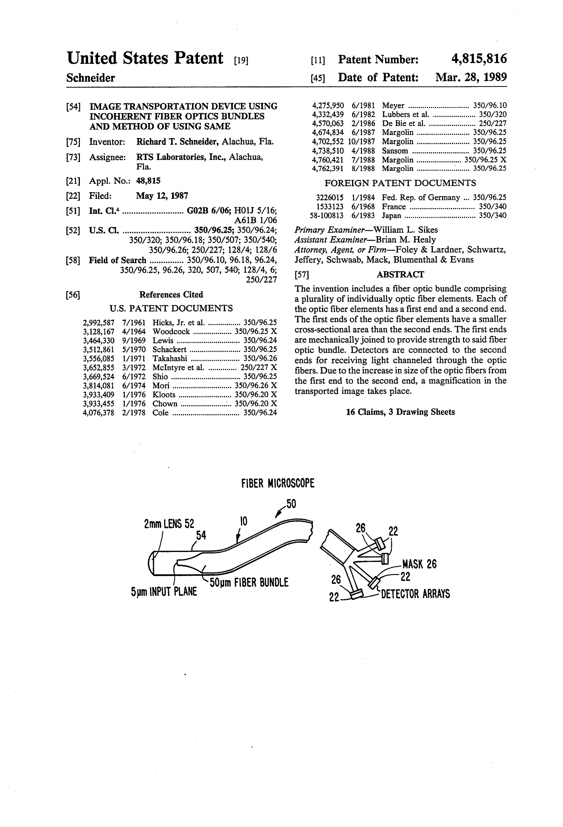
FBER MCROSCOPE
2mm LENS 52 O 26 22
MASK 26
sm (NPut LANE '" 22 DETECTOR ARRAYS
Page 2
Drawing sheet — no readable text.
Page 3
Drawing sheet — no readable text.
Page 4
Drawing sheet — no readable text.
Page 5
inside a throughport of a nuclear reactor, photographic
IMAGE TRANSPORTATION DEVICE USING recording is impossible. One could transport the image NCOHERENT FBER OPTCS BUNDLES AND with relay lenses to a low radiation area and then take METHOD OF USING SAME the picture photographically, or one can use a fiber 5 optics bundle for transportation of the image. Fibers
The U.S. Government has a paid-up license in this which are radiation hardened are available for such an invention and the right in limited circumstances to re application. Therefore, in this case one indeed competes quire the patent owner to license others on reasonable with photographic recording. The fiber optics cable can terms as provided for by the terms of contract No. be snaked around corners, while the relay lenses need a N00014-85-C-0862 awarded by the Dept. of the Navy. 10 clear aperture, giving range to shielding problems. BACKGROUND OF THE INVENTION Therefore, a fiber optic bundle would indeed be prefer able if it could deliver the required resolving power.
1. Field of the Invention The same argument is true for any other periscope The present invention relates to fiber optic bundles arrangement, e.g., for a submarine. Here, also, it would for transporting images, and especially to such fiber 15 be advantageous to replace the relay lenses by a fiber optic bundles which have a high image resolution. optics bundle; however, the resolving power cannot be 2. Discussion of Related Art compromised.
With the advent of fiber optics technology, the op Any application where observation of inaccessible portunity of transporting optical images in fiberbundles locations are attempted, the fiber optics bundle is pref became available. Such bundles conventionally have a 20 erable. If the location is so inaccessible that an optical point-to-point relation between the input and the output relay is not possible, one does not compete with the of the fiber bundle. Such bundles are called "coherent photographic camera anymore, therefore, any resolving bundles” and are in widespread use, e.g. in fiberscopes, power is welcome. If a relay is possible, one has to be etc.
There are, however, certain shortcomings which 25 able to offer a resolving power comparable to the pho tographic camera. Thus, it can be seen that a need has need to be overcome. These relate to the size of the input and output area of the bundle and the diameter of developeding high for a fiber optic device capable of transport resolution images.
the individual fibers used in the bundle.
Since in a coherent bundle, the location of each fiber example, Various fiber optic bundles have been suggested. For has to be identical in the input and output plane, it be 30 Wilcox (U.S. Pat. NO. 3,461,223) uses an or comes more and more difficult to keep track of each dered fiber array which is electronically scanned. It is fiber because as the image area becomes larger the total intended for color television images. The actual image transmission is accomplished by air (UHF) or electrical number of fibers is increased.
Further, in any fiberbundle, the diameter of the indi cable. only,
The fiber array is a decoding and encoding means not a transmission means.
vidual fibers determines the resolving power of the 35 system. The smaller the diameter, the better the resolv Schackert (U.S. Pat. No. 3,512,861) uses a single row ing power. The maximum acceptable diameter depends or a limited number of rows of ordered fibers which are on the application. However, at the same time, the mechanically moved to achieve scanning. Image trans smaller the diameter of the optic fiber, the weaker the mission is through one row (or few rows) of ordered fiber. If the fiber becomes too small, it is difficult if not 40 fibers.
impossible to handle without damage. McIntyre (U.S. Pat. No. 3,652,855) uses an ordered The resolution of an image can be expressed in line fiber optics bundle connected to a limited number (70) pairs/mm. For example, if a resolution of 100 line of photomultiplier tubes. An elaborate coding scheme pairs/mm is needed, and if at least 4 fibers were required between the input fibers and the photomultiplier tubes, per line pair, then a fiber diameter of 1/400 mm=2.5 45 together with a coincidence circuitry, allows obtaining micrometers would be required. A resolution of 100 line of more than 70 pixels. The fiber bundle used is short pairs/mm is achievable with photographic film. Stan and ordered. The coding scheme is specified in greater dard fibers are 50 micrometers; therefore, they produce detail in a successive patent (McIntyre, U.S. Pat. No. a resolution of about 5 line pairs/mm. A 50 micrometer 4,379,967).
fiber is barely visible with the naked eye. Photographic 50 Schaefer (U.S. Pat. No. 4,052,705) describes actually emulsions using this size grain would not be considered a memory device for computers. One could construe acceptable. In principle, glass fibers could be drawn out that it constitutes the transport of images. However, the to 2.5 micrometer diameter, but the mechanical strength bundles (mostly one rowers) are strictly ordered and would be so low that handling of such a bundle would short. They are used to form various types of gates (and, be very difficult, at the least. 55 or, not, etc.).
If a fiber optic bundle is to compete in resolution with The patent to DeBie (U.S. Pat. No. 4,570,063) also a a 35mm camera, 36x400=14400 fibers per image line discloses a one row device which is meant for scanning are required for a total of 24x400=9600 image col a document.
umns or 1.4x 10⁸ fibers altogether. If a fiber optic bun There is no known structure suitable for transporting dle is to compete in resolution with a large sheet film, 60 high resolution images through fiber optics. e.g., chest x-ray (maybe 10X 10 in.), on the order of SUMMARY OF THE INVENTION 1012 fibers are required. These are, of course, fantastic numbers, but they illustrate the basic problem. One object of the present invention is to provide a In view of the foregoing problems, it can be seen that fiber optic bundle which is capable of transporting high it is not always feasible to compete with a 35 mm cam 65 resolution images.
era. However, several scenarios exist where fiber optic Another object of the present invention is to provide bundles can replace cameras. For example, if pictures a fiber optic bundle which is rugged and can be handled are to be taken in high radiation environments, e.g. without fear of damage.
Page 6
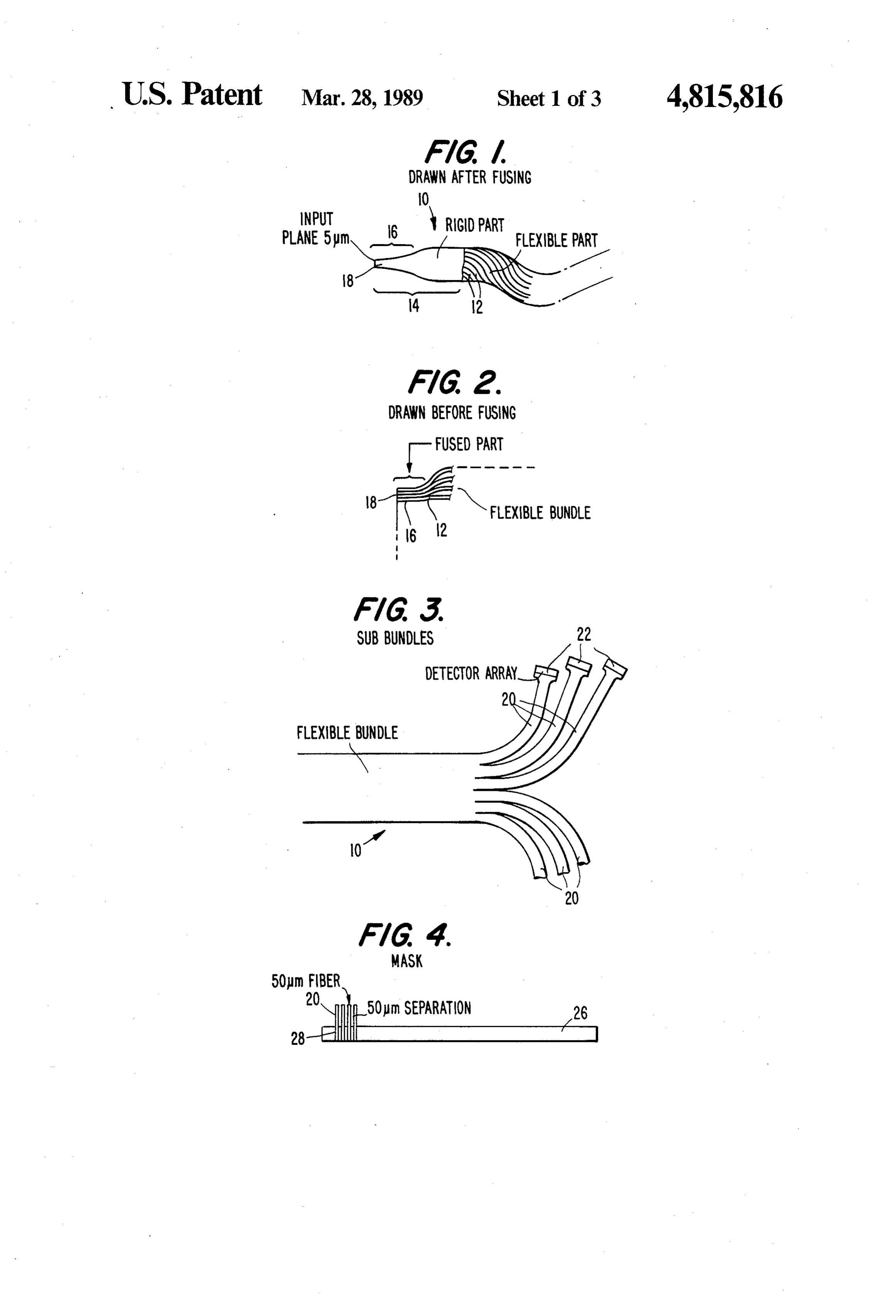
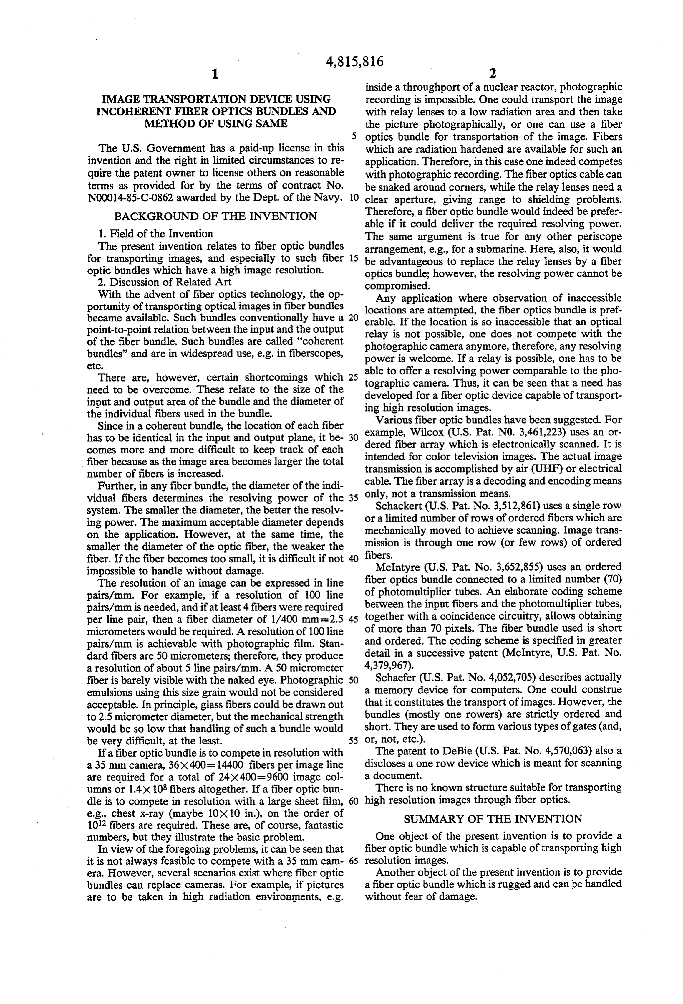
A further object of the present invention is to provide drawings, in which like reference numerals represent a fiber optic bundle which can be manufactured inex like parts throughout, and in which, pensively using randomly oriented fibers, and a system FIG. 1 shows a fiber optic bundle according to the for descrambling the output of the optic bundle to pro present invention produced by drawing the bundle after vide a coherent image. fusing the fibers;
Another object of the present invention is to provide FIG. 2 shows a fiber optic bundle according to the a method of producing a fiber optic bundle capable of present invention being produced by drawing the fibers transporting a high resolution image. before fusing;
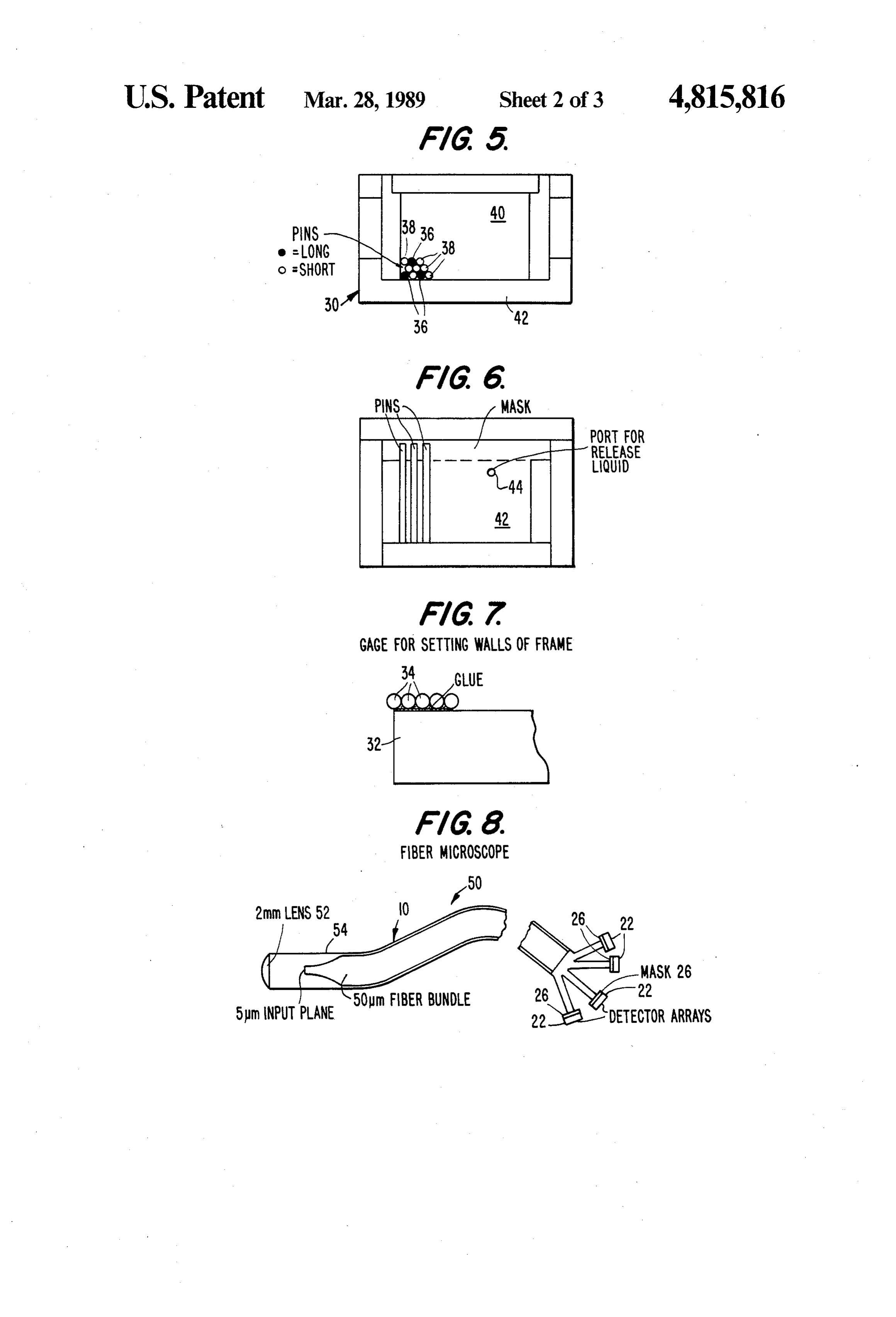
In accordance with the above and other objects, the FIG. 3 shows a fiberr optic bundle according to the present invention is a fiber optic bundle comprising a O present invention connected to a plurality of detectors plurality of individual optic fiber elements, each of on a detector array through a plurality of masks; which has a first end and a second end. The first ends of FIG. 4 shows a mask for use with a fiber optic bundle the optic fiber elements are of a smaller cross sectional according to the present invention; area than the second ends and are mechanically joined FIG. 5 shows a top plan view of a mold for producing together to a fiber optic bundle in order to provide 15 a mask according to the present invention; sufficient strength. A detector array is connected to the FIG. 6 shows a side elevational view of the mold of second ends of the optic fibers for receiving light which FIG. 5;
is transmitted through the fibers from the first ends of FIG.7 shows a gage for setting the walls of the mold the optic fibers. of FIGS. 5 and 6.
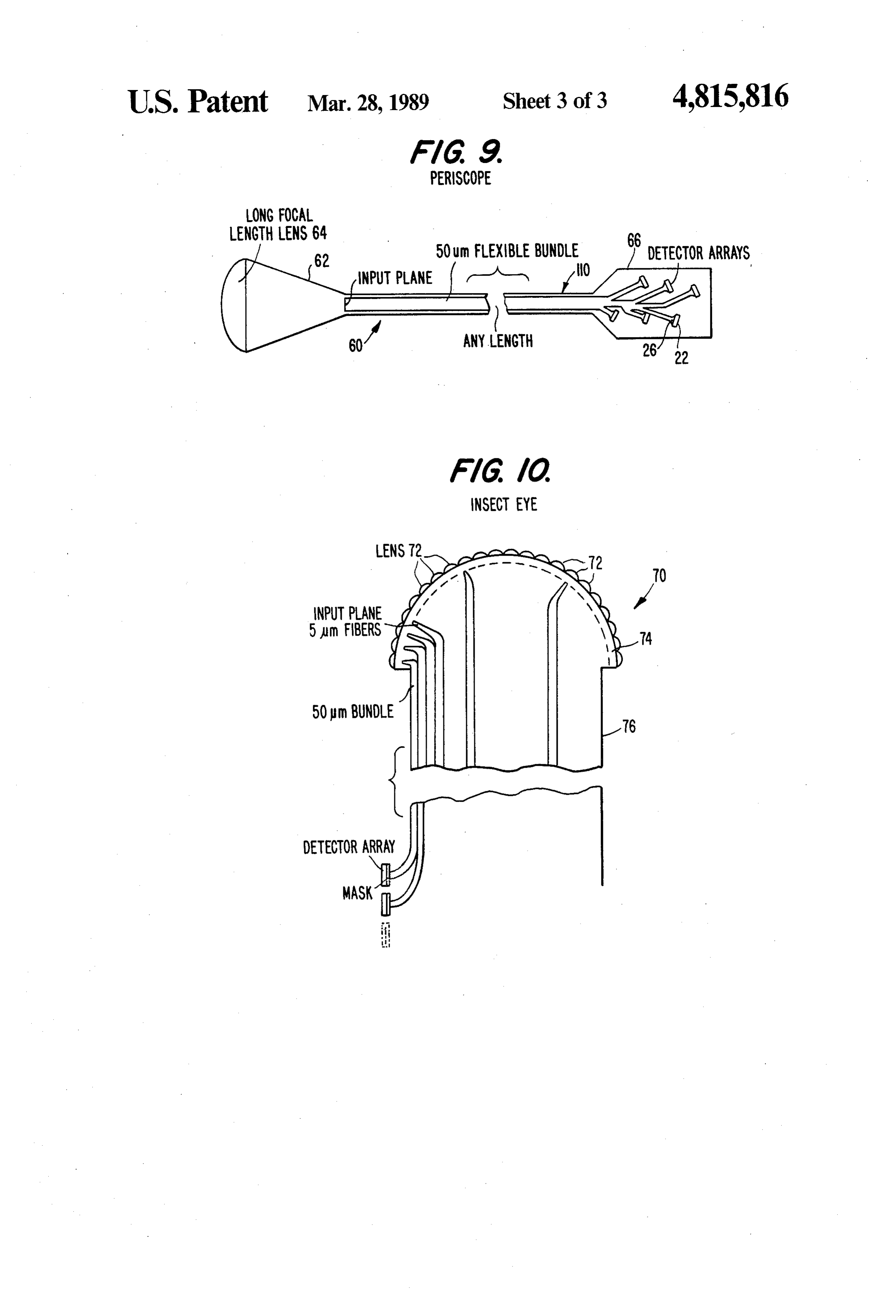
The second ends of the optic fiber elements may be 20 FIG. 8 shows a fiber microscope using a fiber optic joined together into sub-bundles having at least one bundle according to the present invention. optic fiber each, but typically will consist of several FIG. 9 shows a periscope using a fiber optic bundle thousand fibers. One detector array may be connected according to the present invention.
to each sub-bundle. An optical mask may be connected FIG. 10 shows an insects eye using an optic bundle to the fibers formating individual fibers of the sub-bun 25 according to the present invention. dles to individual detectors on the optical detector ar DETAILED DESCRIPTION OF THE ray.
The first end of each optic fiber may be at least as PREFERRED EMBODIMENTS small as about 5 micrometers in diameter and the second The present invention includes fiber optic bundles end of each optic fiber may be at least as large as about 30 having fibers with diameters which are sufficiently 50 micrometers in diameter. small to permit the transmission of high resolution im The second end of each optic fiber may at least an ages by such bundles. Therefore, before discussing the order of magnitude greater in diameter than the first construction of the invention, discussion of what consti end. tutes a suitable fiber diameter for use in the invention The location of the first ends of the optic fibers on the 35 will be set forth. - input plane may be arranged randomly relative to the In order to transmit an image through an optic bun location of the second ends on the output plane, and dle, one would illuminate the input plane of the bundle therefore there may be included a system for descram with a conventional optical system, e.g., a lens, in a way bling light signals received from the second ends to that a sharp image falls on said input plane. The wave produce a correct image of an image projected onto the length of the light used and the diameter of the lens used first ends. determine the angular resolving power. Regardless of The descrambling system may comprise a computer this, the linear resolving power, namely the diameter of program relating the addresses of the input (first) ends the Airy disk, cannot be smaller than the order of mag to the addresses of the output (second) ends and the nitude of the wavelength of the light used. In the case of necessary hardware to display the reconstructed image 45 visible light we may approximate this by 0.5 microme on a monitor. "Address' is here defined as the cartesian ter. Considering lens imperfections, 2.5 micrometers is a coordinate of an individual fiber on the input or output good value for an achievable Airy disk. The resolving plane. power of the human eye in the fovea is considered to be The present invention also includes a method which 5 micrometers which translates to about 100 microme comprises providing a plurality of optic fibers, each 50 ters at reading distance (400 mm). Therefore, for an having a first end and a second end; mechanically join instrument used for visible observations, 50 micrometer ing together the first ends of the optic fibers to form a resolution would be good enough. However, to trans fiber bundle; and reducing the cross section of the first port an image obtained by a telescope (10X), 5 microm end of each optic fiber relative to its second end. eter fiber diameter would be required. In other words, a The step of reducing the cross section of the first ends 55 fiber diameter in the 5-8 micrometer range would be a of the optic fibers may comprise reducing the cross reasonable diameter to meet existing requirements. Con section of each optic fiber individually before connec sequently, for 35 mm format (24x36 mm), a bundle tion to form the bundle. containing about 3.5X10⁷ fibers would be required. Alternatively, the step of reducing the cross section If one had a fiberbundle of such a size one could take of the first ends of the optic fibers may comprise reduc a photographic image of the exit plane of the bundle and ing the cross section of all of the optic fibers together could expect to obtain about the same quality as if the after they are joined together to form the bundle. camera had been located in the entrance plane of the BRIEF DESCRIPTION OF THE DRAWINGS bundle. However, for some applications it is preferable to replace the photographic film by a detector array.
The above and other objects of the present invention 65 The present invention includes a fiber optic bundle of will become more readily apparent when the invention random orientation of the fibers. By allowing the fibers is more fully understood from the detailed description to be randomly oriented, any size bundle of any length to follow, reference being had to the accompanying can be easily assembled from standard 50 micrometer
Page 7
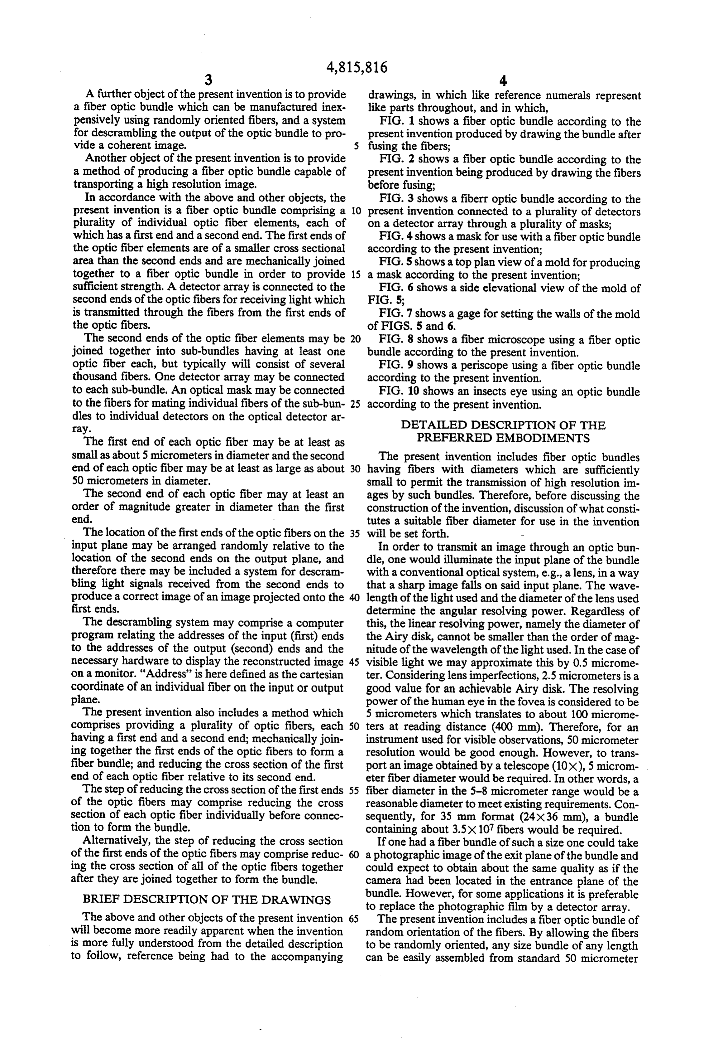
fibers. Of course, with such a bundle, the image will aligned with detector array chip 22 so that each fiber appear to be "scrambled' at the output end of the fiber. end 20 is opposite an individual detector. The alignment The present invention also includes a computerized is accomplished by illuminating the input end 18 of the procedure to unscramble the image. total bundle homogeneously and checking for maxi The fibers themselves are made to be 50 micrometers 5 mum signal output of the detector array. in diameter. These fibers are cemented together at the It is assumed that no space restriction exists at the input end of the bundle for a short length only. The output end. Nevertheless, the output end (including so-formed rigid part is drawn out using a suitable dead space) should not be larger than a factor of 20 amount of heat until the diameter of the bundle is re times the size of the input end. Therefore, the 36 mm duced by a factor of 10 at the input end. A fiber bundle 10 input end dimension would grow into a 70 cm output 10 is shown in FIG. 1 having a plurality of fibers 12 end dimension.
connected together for a predetermined length 14. The As will be understood from the foregoing discussion, connected fibers have been drawn down to the desired despite the fact that the output ends of the fibers are 50 size in the region 16. The fibers having the smallest micrometers each, the resolving power of the bundle is cross sectional area form the input end 18 of the bundle. 15 still 5 micrometers. A bad detector (50 micrometer), The individual fibers at the opposite end of the bundle therefore, results in a loss of a 5 micrometer pixel. are separate from one another. Descrambling of the signals at the output end is ac It is noted that in the structure shown in FIG. 1, the complished by projecting a family of curves onto the fibers were connected first and then drawn down to input end of the total bundle. The curves may form an size. An alternate method is shown in FIG. 2 in which orthogonal grid with reasonable spacing. The grid spac each individual fiber 12 is drawn until its end 16 is down ing can be varied at successive projections, or the lines to 5 micrometers during the manufacturing process. may be just shifted and the grid spacing may be kept The ends are then cemented together to form the input constant. In either case, the intersection of a vertical plane. line and a horizontal line defines a pixel of the overall If silica glass fibers are used, the drawing process is 25 image, and also constitutes the address of the underly well known technology. If plastic fibers are used, a butt ing fiber. The output end of each individual fiber is joint is used between the polished end of the 50 microm connected to one certain detector. The address of this eter plastic fiber bundle and a short rigid conical piece detector is determined by illuminating one pixel only on of a drawn out (drawn from 50 to 5 micrometers) silica the input plane of the fiberbundle. Pixel addresses and glass fiber bundle. 30 the corresponding detector addresses are stored in pairs It should be understood that the individual 5 microm to form a look-up table to "translate' a scrambled image eter fibers are fragile and difficult to handle without received by the detector array into the original image as damage. Accordingly, the connection of these fibers to it appeared on the input plane. This look-up table is, of one another enhances the strength of the individuals course, different for each bundle manufactured and is and enables them to be easily handled. Also, by main 35 therefore to be provided to the user along with the taining the 50 micrometer size of the output ends of the cable.
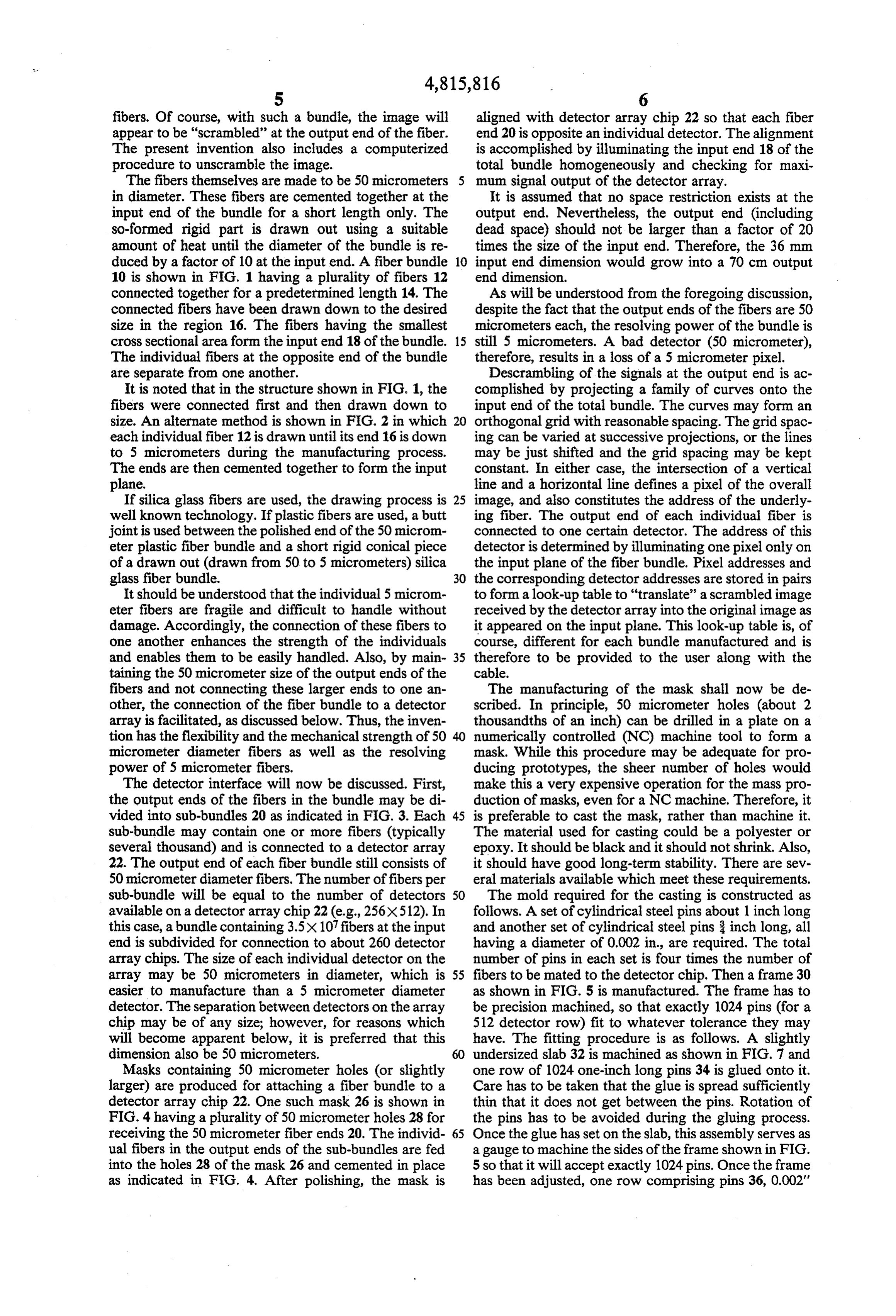
fibers and not connecting these larger ends to one an The manufacturing of the mask shall now be de other, the connection of the fiber bundle to a detector scribed. In principle, 50 micrometer holes (about 2 array is facilitated, as discussed below. Thus, the inven thousandths of an inch) can be drilled in a plate on a tion has the flexibility and the mechanical strength of 50 numerically controlled (NC) machine tool to form a micrometer diameter fibers as well as the resolving mask. While this procedure may be adequate for pro power of 5 micrometer fibers. ducing prototypes, the sheer number of holes would The detector interface will now be discussed. First, make this a very expensive operation for the mass pro the output ends of the fibers in the bundle may be di duction of masks, even for a NC machine. Therefore, it vided into sub-bundles 20 as indicated in FIG. 3. Each 45 is preferable to cast the mask, rather than machine it. sub-bundle may contain one or more fibers (typically The material used for casting could be a polyester or several thousand) and is connected to a detector array epoxy. It should be black and it should not shrink. Also, 22. The output end of each fiber bundle still consists of it should have good long-term stability. There are sev 50 micrometer diameter fibers. The number of fibers per eral materials available which meet these requirements. sub-bundle will be equal to the number of detectors SO The mold required for the casting is constructed as available on a detector array chip 22 (e.g., 256X512). In follows. A set of cylindrical steel pins about 1 inch long and another set of cylindrical steel pins inch long, all this case, abundle containing 3.5X10⁷ fibers at the input end is subdivided for connection to about 260 detector having a diameter of 0.002 in., are required. The total array chips. The size of each individual detector on thenumber of pins in each set is four times the number of array may be 50 micrometers in diameter, which is 55 fibers to be mated to the detector chip. Then a frame 30 easier to manufacture than a 5 micrometer diameter as shown in FIG. 5 is manufactured. The frame has to detector. The separation between detectors on the array be precision machined, so that exactly 1024 pins (for a chip may be of any size; however, for reasons which 512 detector row) fit to whatever tolerance they may will become apparent below, it is preferred that this have. The fitting procedure is as follows. A slightly dimension also be 50 micrometers. 60 undersized slab 32 is machined as shown in FIG. 7 and Masks containing 50 micrometer holes (or slightly one row of 1024 one-inch long pins 34 is glued onto it. larger) are produced for attaching a fiber bundle to a Care has to be taken that the glue is spread sufficiently detector array chip 22. One such mask 26 is shown in thin that it does not get between the pins. Rotation of FIG. 4 having a plurality of 50 micrometer holes 28 for the pins has to be avoided during the gluing process. receiving the 50 micrometer fiber ends 20. The individ 65 Once the glue has set on the slab, this assembly serves as ual fibers in the output ends of the sub-bundles are fed a gauge to machine the sides of the frame shown in FIG. into the holes 28 of the mask 26 and cemented in place 5 so that it will accept exactly 1024 pins. Once the frame as indicated in FIG. 4. After polishing, the mask is has been adjusted, one row comprising pins 36, 0.002'
Page 8
in diameter and 1" long alternating with pins 38, 0.002" lens (which is ordered). The output end of the fiber in diameter and 3' long, is glued into it. After the glue bundle will be divided into sub-bundles. has set, another row of pins 36 alternating with pins 38 The individual fibers in the sub-bundles are termi being offset (dense packing) from the first row in a way nated in masks which mate each individual fiber to its that the second row of pins lies between the l' pins and own individual detector. This mating procedure per the 3" pins of the first row is glued in place. The next mits a 5 micrometer resolution using 50 micrometer row again contains pins 36 and 38 of alternating lengths, detectors. It also permits the individual detectors to be and soon (see FIG. 5). Then the frame is closed. The separated from each other sufficiently without suffering next step is to destroy the glue by heating the frame in a loss in resolution.
an oven. The back plate 40 of the frame is removed and 10 Descrambling itself is a known process for producing the back ends of the pins are silver soldered in a hydro a coherent image from a random array of optic fibers. However, the manner in which the descrambling is gen furnace oven. The front end of the assembly is now achieved the mold for the mask. A threaded plug on the side plate in the present invention is a unique computer 42 is now removed and fitted with a nipple 44 to supply ized procedure. The input plane being random, by pro a pressure release medium (e.g., water) to the mold for 15 jecting an orthogonal grid (or a set of concentric circles removing the product after pouring. A suitable mold with radii) onto the input plane, a matrix of input points is so defined.
release should also be used.
To form a mask, the plastic material is poured into the The size of the input point, depending on the applica mold and allowed to set. Once set, the completed mask 20 tion, can be chosen such that either one or more than is removed by injecting the pressure release medium, one detector is affected at the output end by one input such as water, into the nipple 44 causing pressure to point. This is different from making the detectors build up below the mask, forcing the mask from the smaller than the fiber diameter. Our detectors are larger than the fiber diameter, and yet we still can assign, if so mold.
Alternatively, a mold such as that shown in FIGS. 5 desired,The more than one detector to one individual input and 6 can be used in a conventional injection molding 25 point.
neighboring detectors affected by one input point are not detectors. The fibers leading to these de machine to mass produce masks. tectors are only neighboring for a short length. There The transition from the 5 micrometer fiber plane to fore the effect of "cross talk” between fibers is greatly the 50 micrometer fiber plane (as in FIG. 2) can also be reduced.
accomplished with a coherent fiber bundle. Starting 30 Various applications in which the optic fiber bundle from coherent stock which is ordinarily used to pro duce a rigid fiber optic image conduit consisting of soft of the present invention can be readily used will now be discussed. It will be understood that these application glass fibers, rigidly fused together into a rod, one end of also form part of the invention. such a rod is drawn by a factor of 5-10. After the draw A fiber microscope (fiberscope) is an optical instru ing process, both ends are polished. 35 ment made in accordance with the present invention The resulting product still has a point-by-point corre lation between entrance and exit plane. The fiber ends having an objective with a short focal length, on the order of 4 mm. Since the diameter of a lens and its focal on the entrance plane are now 5 micrometers (densely packed) in diameter while the fiber ends on the exit length are linked together by the f-number, such an objective lens will also have a small diameter. The pres plane are 50 micrometers (also densely packed) in diam ent invention is ideally adapted to produce a fiberscope eter.
having an objective
This configuration will be referred to below as a than 2 mm, e.g., for insertion lens with a diameter of not more into arteries, etc. FIG. 8
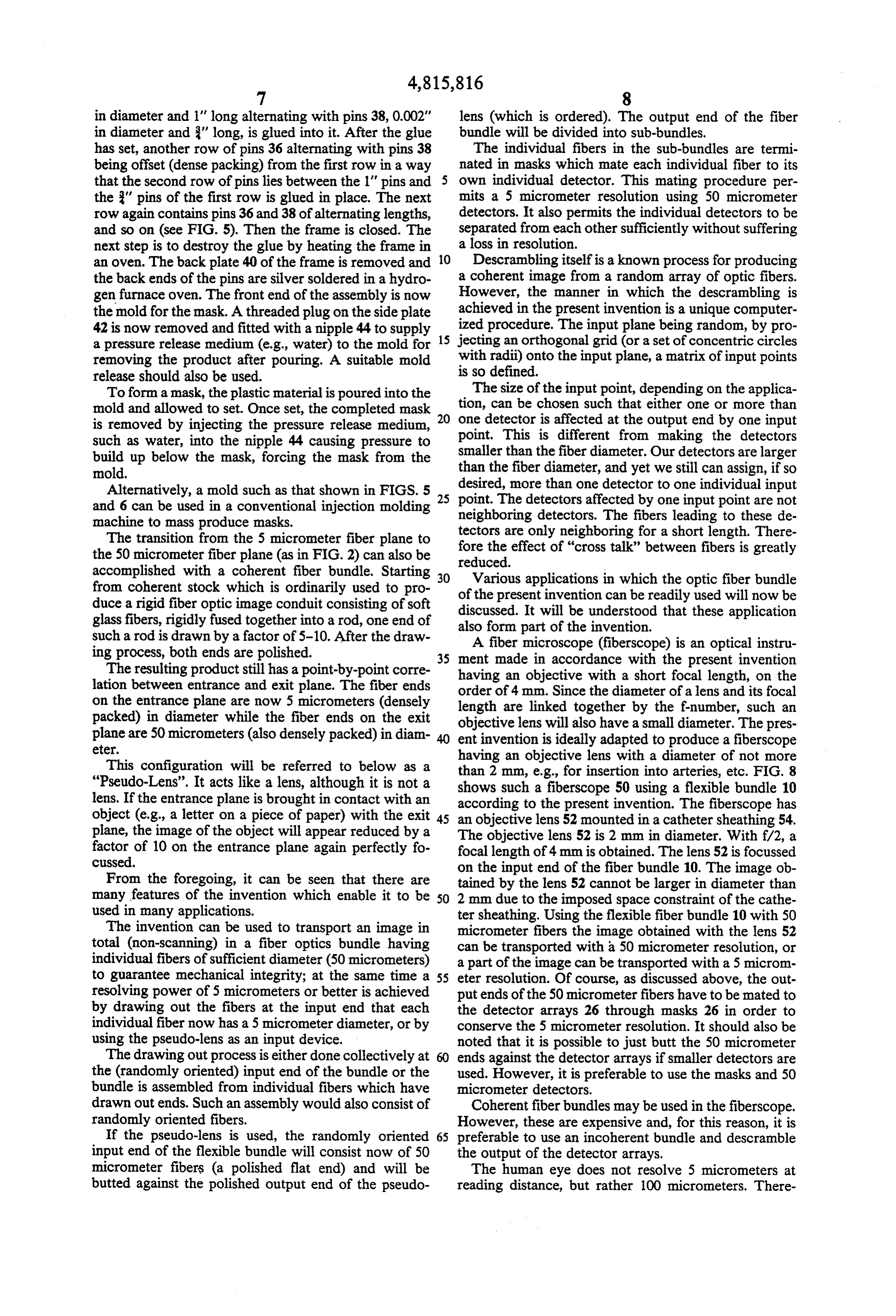
"Pseudo-Lens'. It acts like a lens, although it is not a shows such a fiberscope 50 using a flexible bundle 10 lens. If the entrance plane is brought in contact with an according to the present invention. The fiberscope has object (e.g., a letter on a piece of paper) with the exit 45 an objective lens 52 mounted in a catheter sheathing 54. plane, the image of the object will appear reduced by a The objective lens 52 is 2 mm in diameter. With f/2, a factor of 10 on the entrance plane again perfectly fo focal length of 4 mm is obtained. The lens 52 is focussed cussed. on the input end of the fiber bundle 10. The image ob From the foregoing, it can be seen that there are tained by the lens 52 cannot be larger in diameter than many features of the invention which enable it to be 50 2 mm due to the imposed space constraint of the cathe used in many applications. tersheathing. Using the flexible fiber bundle 10 with 50 The invention can be used to transport an image in micrometer fibers the image obtained with the lens 52 total (non-scanning) in a fiber optics bundle having can be transported with a 50 micrometer resolution, or individual fibers of sufficient diameter (50 micrometers) a part of the image can be transported with a 5 microm to guarantee mechanical integrity; at the same time a 55 eter resolution. Of course, as discussed above, the out resolving power of 5 micrometers or better is achieved put ends of the 50 micrometer fibers have to be mated to by drawing out the fibers at the input end that each the detector arrays 26 through masks 26 in order to individual fiber now has a 5 micrometer diameter, or by conserve the 5 micrometer resolution. It should also be using the pseudo-lens as an input device. noted that it is possible to just butt the 50 micrometer The drawing out process is either done collectively at ends against the detector arrays if smaller detectors are the (randomly oriented) input end of the bundle or the used. However, it is preferable to use the masks and 50 bundle is assembled from individual fibers which have micrometer detectors.
drawn out ends. Such an assembly would also consist of Coherent fiberbundles may be used in the fiberscope. randomly oriented fibers. However, these are expensive and, for this reason, it is If the pseudo-lens is used, the randomly oriented 65 preferable to use an incoherent bundle and descramble input end of the flexible bundle will consist now of 50 the output of the detector arrays.
micrometer fibers (a polished flat end) and will be The human eye does not resolve 5 micrometers at butted against the polished output end of the pseudo reading distance, but rather 100 micrometers. There
Page 9
fore, if the computer connected to the detector arrays paths of the target can be predicted by a computer 22 presents the information from the arrays to the ob program based on previous path data to make sure that server with such a resolution (meaning each 5 microme the correct detector array is read next, while the previ ter object point is represented by a 100 micrometer ous image is held on the screen until the new image diameter dot on the screen), the image is, in fact, magni appears. Since each lens stares at a certain section in fied by a factor of 20. That is the reason why the fiber space, the position of the target is easily obtainable and scope 50 can function as a microscope if the bundle 10 can be displayed on the screen. Multiple targets can be is used to transport images, but does not function as a displayed on multiple screens. microscope if a conventional fiber bundle is used to Still another application of the present invention is to transport the images. 10 coat-in lieu of using an optical system-the first ends The fiber bundle 10 of the present invention can also of the fiberoptic cables with a material which fluoresces be used to produce a periscope device 60, as shown in under irradiation with ionizing radiation, such as x-rays, FIG. 9. The periscope device 60 has a sheathing 62 in gamma rays, beta and alpha particles. A typical material which the bundle 10 is mounted and also includes a lens may be zinc sulfide. The effect will be that the detectors 64 which is focussed on the input end of the bundle 10. 15 on the detector arrays mated to the sub-bundle will In this application it is assumed that the required resolu receive visible light, the intensity of which is related to tion on the input end of the fiber bundle 10 is 50 mi the intensity of the ionizing radiation, which irradiated crometers, but a fairly large input plane is required (e.g., the first ends of the fibers. By reading the detector 24x36mm). This infers a large lens 64 having a long arrays correctly, meaning using the look-up tables focal length. It is also assumed that the application re 20 which translate input addresses to output addresses, an quires images to be transported over a large distance, X-ray image can be constructed and displayed on the e.g., 100 feet. Due to the size and length of the fiber computer monitor, which is identical to a photographic bundle, it needs to be flexible and incoherent. The ap X-ray, which one would have obtained when placing a proximate 260 detector arrays 22, of course, do not need photographic X-ray film in the input plane. to be arranged in one plane. They can be staggered and 25 The foregoing description is set forth for the purpose so fill the volume of a cylinder 66 as indicated in FIG. of illustrating the present invention but is not intended 9. In this way, the size of the receiving end of the system to limit the invention. Clearly, numerous additions, is still moderate. Also, the periscope sheathing can be in substitutions and other modifications can be made to the the form of a rigid tube or can be a flexible cable which invention without departing from the scope of the in can be rolled upon a drum. Further, as would be appar 30 vention as set forth in the appended claims. ent to one of ordinary skill in the art, the lens 64 can be What is claimed is:
oriented in any direction relative to the bundle 10 as 1. An apparatus, comprising: long as it remains focussed on the input end of the bun a fiber optic bundle, comprising: dile. a plurality of individual optic fiber elements, each Another application of the present invention is in the 35 of said optic fiber elements having a first end and production of an insect eye type construction for pro a second end, the first ends of said optic fiber ducing a panoramic view. Assume there is plenty of elements being of a smaller cross sectional area illumination and a sentry is required which looks in all than said second ends, said first ends of said optic directions simultaneously (e.g., on a carrier for display fibers being mechanically joined to provide of approaching aircraft). Here 10x magnification 40 strength to said fiber optic bundle; would be appreciated, so that 5 micrometer resolution said second ends of said optic fiber elements being on the input plane is required if a 50 micrometer output connected in sub-bundles, each sub-bundle com end is used. A roving (scanning) camera may be too prising more than one optic fiber; slow to cover the total hemisphere. In an insect eye a light source for projecting light on said first ends device 70 as shown in FIG. 10, a relatively small lens (2 45 of said optic fiber elements; and mm) can provide the required resolution. The insect eye means for receiving light from the second ends of device comprises a plurality of individual lenses 72 said optic fibers, which are spread over a hemispherical support 74. Each said receiving means includes an optical detector lens is focussed on one bundle 10 and the bundles 10 array connected to each sub-bundle, wherein said converge in a transport tube 76. The transfer tube 76 50 first ends of said optic fibers are arranged randomly may penetrate a housing such as a ship's hull or the like. relative to said second ends, and wherein said re The resulting "dome' of lenses is of reasonable size ceiving means includes means for descrambling since the input end of each bundle can be made quite light signals received by said second ends to repro small, as discussed above. The number of lenses re duce a correct image of an image projected onto quired is very large and consequently the number of 55 said first ends.
detector arrays required for read out is also large. The 2. An apparatus according to claim 1 wherein said exact number of lenses required depends on the actual receiving means further includes an optical mask for resolution required. mating the fibers of the sub-bundles to the optical detec It would be difficult to display the data from all of the tors on said optical detector array. lenses at the same time. Therefore, it would be prefera 60 3. An apparatus according to claim 1 wherein said ble to display only a small fraction of data from the first end of each optic fiber is at least as small as about detector arrays at one time. The detector arrays can be 5 micrometers in diameter.
scanned to provide a moving image on a display screen. 4. An apparatus according to claim 3 wherein said In this way, a moving target could be followed by ac second end of each optic fiber is as large as about 50 cessing the correct arrays at the correct time. Also, it is 65 micrometers in diameter.
preferable to leave gaps between the individual fields of 5. An apparatus according to claim 1 wherein said view of the many lenses. In this way, a target would second end of each optic fiber is at least an order of disappear and reappear periodically. Of course, the magnitude greater in diameter than said first end.
Page 10
6. An apparatus according to claim 1 wherein said lines, the intersections of which define addresses of descrambling means comprises means for displaying a input points from said first ends of said optic fibers. matrix of lines, the intersections of which define ad 13. An apparatus, comprising: dresses of input points on said first ends of said optic 5 a fiber optic bundle, comprising: fibers. a plurality of individual optic fiber elements, each 7. An apparatus according to claim 1 including a lens of said optic fiber elements having a first end and focussed on said first ends of said fibers. a second end, said first ends of said optic fiber 8. An apparatus according to claim 7 wherein said elements being arranged randomly relative to lens and said fiber optic bundle are contained in a cathe 10 said second ends, the first ends of said optic fiber ter sheathing. elements being of a smaller cross sectional area 9. An apparatus according to claim 7 wherein said than said second ends, lens and said fiber optic bundle are contained in a peri wherein the second ends of said optic fiber ele ments are connected in random sub-bundles, scope tube. each comprising more than one optic fiber ele 10. An apparatus according to claim 1 including a 15 ment end, the optic fiber element second ends in plurality of fiber optic bundles and a plurality of lenses each sub-bundle being randomly arranged rela focussed, respectively, on said fiber optic bundles, said tive to the optic fiber element first ends; lenses being positioned over a hemisphere. means for projecting an image onto the first ends of 11. A method of making optic fiberbundles, compris the optic fiber elements; and 1ng: 20 means for receiving light from the second ends of providing a plurality of optic fibers, each having a said optic fiber elements in all of said sub-bun first end and a second end; dles, including means for descrambling light mechanically connecting the first ends of said optic signals received by all of said sub-bundles to fibers to form a fiber bundle; reproduce the image projected onto said first reducing the cross section of the first end of each 25 ends.
optic fiber relative to its second end; and 14. An apparatus according to claim 13 wherein said connecting said second ends of said optic fibers into tainingreceiving means includes an optical detector array con sub-bundles having more than one second end a plurality of optical detectors connected, re each, wherein an image is projected on the first end 30 spectively,
to said sub-bundles.
apparatus according to claim 14 wherein said to be sensed at the second end and wherein the step receiving means further includes an optical mask for of mechanically connecting said first ends of said mating optic fiber bundles comprises connecting them optical detectors on said opticalofdetector the optic fiber elements the sub-bundles to the array.
such that the orientation of said first ends is random 16. An apparatus according to claim 13 wherein said relative to said second ends, further including the 35 optic fiber element first ends are arranged in sub-bun step of descrambling the sensed image at said sec dles, the sub-bundles of optic fiber element first ends ond ends. being random relative to the sub-bundles of optic fiber 12. The method according to claim 11 wherein said second ends.
step of descrambling comprises displaying a matrix of k k
Provenance
- Collection
- Patents citing this work
- Original assignee
- RTS Laboratories Inc
- Pages
- 10
- Method
- pdftotext (the PDF's own text layer) + pdftoppm 300dpi page scans
- Patent office record
- patents.google.com →
- Source
- Google Patents citing-documents table
- Inventors
- Richard T. Schneider; RTS Laboratories Inc
- Published
- 1989-03-28
- Transcribed from
- patentimages.storage.googleapis.com →