patent · US3933455
Method for joining optical fibre bundles
20 January 1976
Page 1 — bibliographic record
35 ) is 96 J. SK
United States Patent (19) 11 3,933,455 Chown (45) Jan. 20, 1976 54 METHOD FOR JOINING OPTICAL FIBRE 3,579,316 5/197l Dyott et al................................ 65/4 BUNDLES 3,830,667 8/1974 Carpenter................................. 65/4 75) Inventor: Martin Chown, Harlow, England 73) Assignee: International Standard Electric Primary Examiner-Robert L. Lindsay, Jr. Corporation, New York, N.Y. Attorney, Agent, or Firm-John T. O'Halloran; (22 Filed: May 17, 1974 Menotti J. Lombardi, Jr.
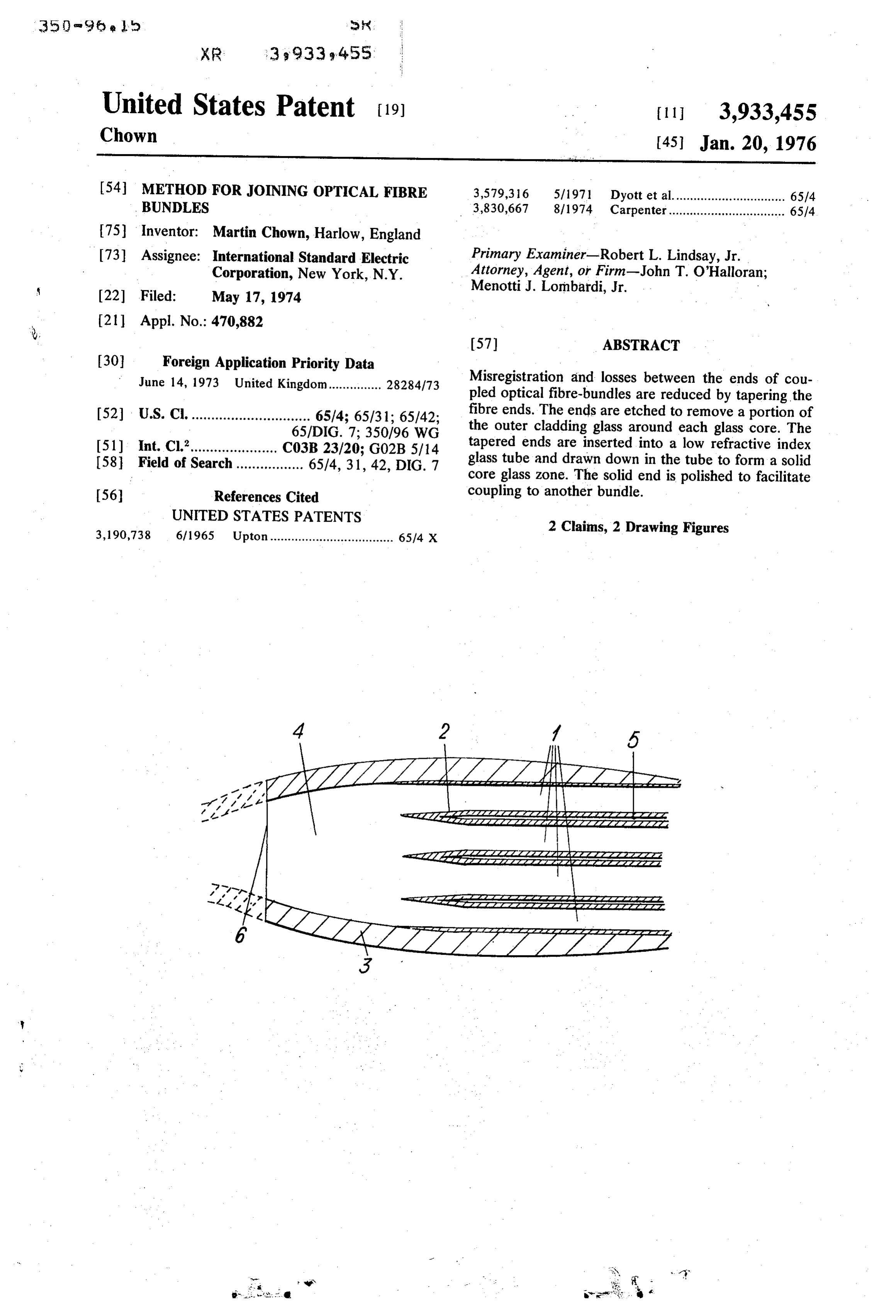
R. 57 ABSTRACT 30 Foreign Application Priority Data
J s 3 pp. ca ion riority Ua Misregistration and losses between the ends of cou une 4, nited Kingdom............... ''' pled optical fibre-bundles are reduced by tapering the fib Thtohed t tion of (52) U.S. C. .............................. 65/4; 65/31; 65/42; E. EGd t pote: 51) Int. Cl. c6.26,883 Y. tapered ends are inserted into a low refractive index 58 id f s h ow w a 65/4, 3 42, DG. 7 glass tube and drawn down in the tube to form a solid e O. SC ................ y w a y as core glass zone. The solid end is polished to facilitate 56) References Cited coupling to another bundle. UNITED STATES PATENTS 2 Claims, 2 Drawing Figures 3,190,738 6/1965 Upton................................... 6514 X
aZZZZ242 ZZZZZZZZZZZZZZZZZZZ aZZAZZZZZZZZZZZZZZZaataaaaaaa.
scazaaaaaaaaaaaZ eaaaaaaaaaaaaaaaaaaaaaaaaaaaaay
Page 2
Drawing sheet — no readable text.
Page 3
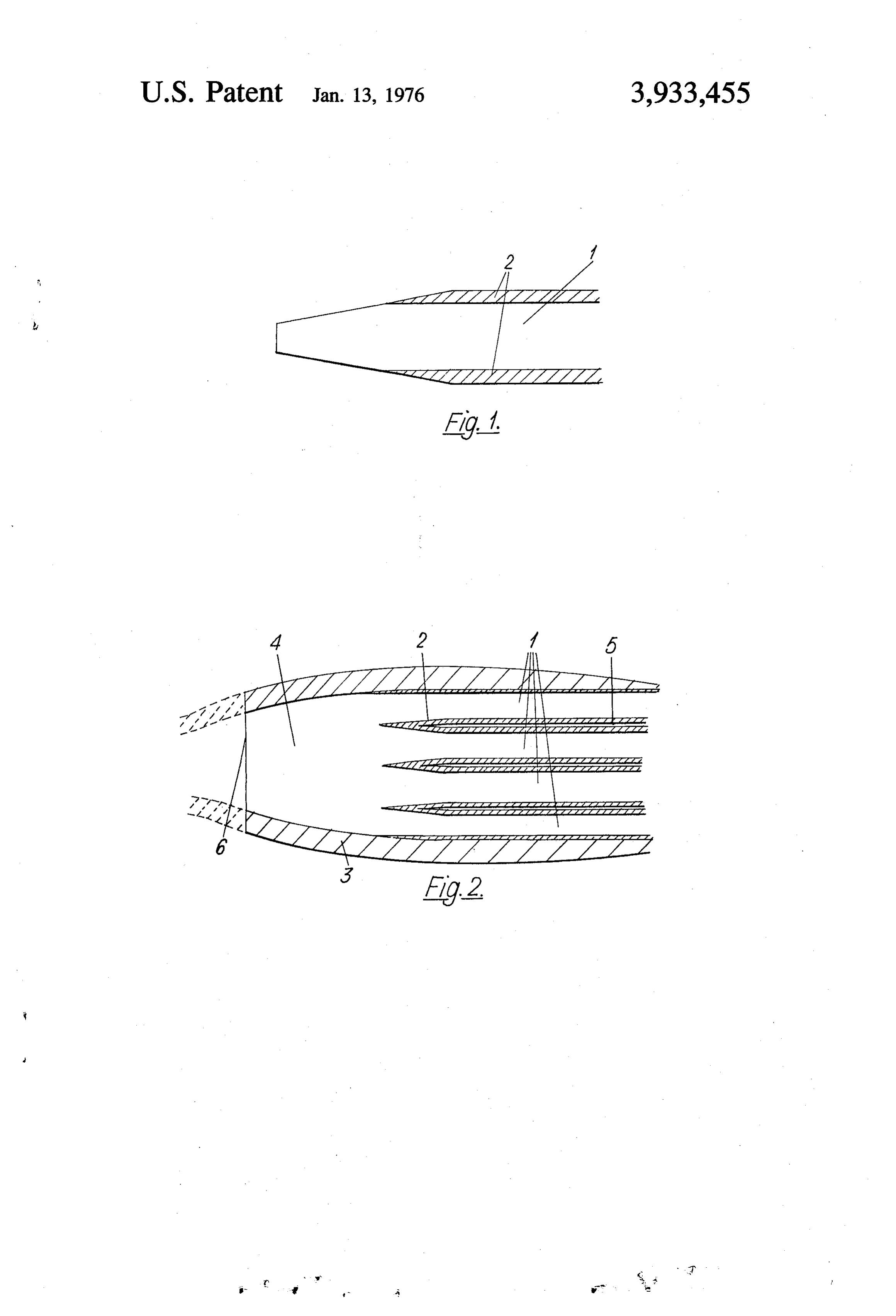
FIG. 2 depicts schematically an axial section through
METHOD FOR JOINING OPTICAL FIBRE the coupling region of the entire optical fibre-bundle.
BUNDLES
DESCRIPTION OF THE PREFERRED
BACKGROUND OF THE INVENTION EMBODIMENT 1. Field of the Invention The fibres at one end of an optical fibre optic bundle This invention relates to the launching of light into are tapered by etching. An individual fibre of the bun optical fibre-bundles and particularly to a novel cou dle is depicted in FIG. 1, and comprises a central region pling arrangement between the fibre ends. 1 of core glass, typically 70 u diameter, surrounded O by lower refractive index cladding glass 2 typically 2. Description of the Prior Art
Optical coupling between one fibre-bundle and an 4 I thick. The fibre optic bundle typically contains other may be achieved by polishing the ends of the 500 to 1000 such fibres. The etching of the fibre ends is designed to remove entirely the cladding glass from a bundles and placing a polished end of one bundle in short section at their extreme ends and to provide a close proximity with one of the polished ends of the other bundle. Unless special measures are taken to 15 gradual fibres transition from there to the region where the have their full thickness of cladding glass. The ensure that the ends of individual fibres of the first bundle all register exactly with the ends of fibres of the bundle and slowly by taper is provided gathering the fibres into a loose lowering their ends into a hydroflu second bundle the randomness of registration will con oric acid etch at a controlled rate. A selective etch tribute to optical loss in the coupling. Some of the light 20 which would preferentially etch the cladding glass will not be launched into the cores of the fibres of the would be an advantage, but is not essential. second bundle but will be lost through being launched The fibre ends are then rinsed, cleaned, and inserted either into the cladding or into the interstices between into the bore of a glass tube 3 (FIG. 2) of lower refrac fibres. In a typical close packed multi-mode optical tive index than the fibre cores 1. Next the assembly of fibre-bundle only about 60% of the total cross section 25 tube and fibre ends is heated to fuse it and is drawn of the bundle is provided by the fibre cores, and hence down to provide a zone 4 from which interstices 5 the loss arising from lack of registration will be a signifi between fibres have been eliminated. Finally, the fibre cant proportion of the total loss of such a coupling. bundle is served, ground and polished within the zone 4 This problem of launching efficiency is not confined to to provide an end face 6.
the launching of light from one fibre-bundle into an 30 If the fibre-bundle is to be directly coupled to an other, but is a general problem affecting the launching other, one factor contributing to optical loss in the of light into a fibre-bundle from any light source. coupling is mismatch between the adjacent end diame ters of the two bundles. The presence of a taper in the
SUMMARY OF THE INVENTION zone 4 means that, within a limited range of values, the It is therefore the primary object of the present in 35 diameter of the end face 6 may be selected by sitting it vention to provide an improved method for coupling an appropriate distance along the length of the Zone 4. ends of fibre-bundles with minimum losses from mis It is to be understood that the foregoing description registration. of a specific example of this invention is made by way According to the present invention, this is achieved of example only and is not to be considered as a limita by forming a novel coupling region at at least one of the 40 tion on its scope.
What is claimed is:
ends of a glass optical fibre-bundle. The method in cludes the steps of etching the fibres at that end of the one1. ofAthe method of providing a coupling region at least bundle to produce tapered ends to the fibres, of insert a plurality ends of of a glass optical fibre-bundle including glass fibres each having an inner core ing the tapered ends into the bore of a glass tube having 45 glass and outer cladding glass, which method includes a lower refractive index than that of the fibre cores, of the steps of etching the fibres at that end of the bundle fusing the assembly of tube and fibre ends while draw to remove the cladding glass and produce tapered ends ing it down so as to provide a zone from which inter to the individual fibres, of inserting the tapered ends stices between the side walls of the tapered ends of the into the bore of a glass tube having a lower refractive fibres have been eliminated, and of providing the fibre 50 index than that of the fibre cores, of heating and fusing bundle with a polished end within said Zone. the assembly of tube and fibre ends while drawing it There follows a description of the provision of a fibre down so as to provide a solid Zone of core glass within optic bundle having a coupling region embodying the the tube and to eliminate the cladding glass and inter invention in a preferred form. The description refers to stices between the side walls of the tapered ends of the the accompanying drawings. 55 fibres in said Zone, and of forming a polished end within said Zone.
BRIEF DESCRIPTION OF THE DRAWINGS
2. The method of claim 1 including severing the
FIG. 1 depicts the end regions of an individual optical fibre-bundle within said end zone and grinding and fibre of a fibre-bundle after it has been provided with a polising the severedckends to* providesk an end face. taper, and 60
Provenance
- Collection
- Cited prior art
- Original PDF
- patentimages.storage.googleapis.com →
- Filed
- 1974-05-17
- Pages
- 3
- Method
- pdftotext (the PDF's own text layer) + pdftoppm 300dpi page scans
- Source
- Google Patents bibliographic record
- Granted
- 1976-01-20
- Inventors
- Martin Chown; International Standard Electric Corp
- Transcribed from
- patentimages.storage.googleapis.com →