patent · US3669524
Bright illuminator for microscopes
13 June 1972
Page 1
Drawing sheet — no readable text.
Page 2
United States Patent Office Patented June 13, 1972
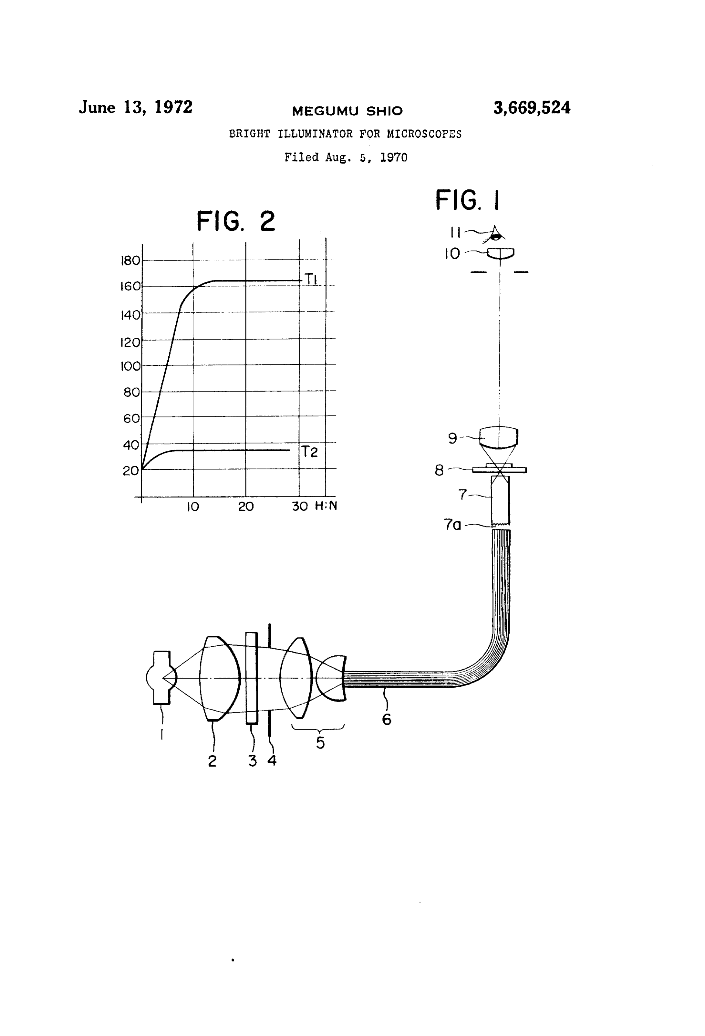
BRIEF DESCRIPTION OF THE DRAWING
3,669,524 FIG. 1 is a diagrammatic view illustrating an optical BRIGHT LLUMNATOR FORMCROSCOPES system of one embodiment of the present invention; and Megumu Shio, Tokyo, Japan, assignor to Nippon
Kogaku K.K., Tokyo, Japan FIG. 2 is a graph illustrating the temperature rise at the Filed Aug. 5, 1970, Ser. No. 61,280 entrance and exit of a light guide thereof. Claims priority, application Japan, Aug. 8, 1969, DESCRIPTION OF THE PREFERRED 44/74,827 EMBODIMENT
US, C, 35087 1 Claim Referring to FIG. 1, reference numeral 1 designates a O point source of light such as xenon lamp or ultra-high pressure mercury lamp with a very bright intensity; 2, a
ABSTRACT OF THE DISCLOSURE collector lens; and 5, a condenser lens which constitutes This invention provides a high brightness illuminating one condenser system together with the collector lens 2.3 device for microscopes. The device includes a light source, 15 is a heat insulating filter and an iris adjustable diaphragm a condenser system consisting of a condenser lens and a 4 is interposed between the collector lens 2 and the con collector lens, an iris diaphragm, a heat ray absorbing fil glass denser lens 5. 6 is a light guide (optical fibers made of ter, a light guide and a cylindrical mirror. The iris dia fibers) whose one end is fixed to one surface of the phragm and the filter are placed between the collector condenser lens 5 and is adjacent to the focus of the con lens and the cendenser lens. One end of the light guide is 20 fix denser optical system. However, it is not necessary to placed very close to the condenser lens and at the other the optical guide 6 to the condenser lens 5. The nu end of the light guide the cylindrical mirror is placed. The merical aperture of illumination of light guide is adjusted cylindrical mirror has a finished and chromium plated by the diaphragm 4. The light guide 6 has an optical char mirror surface and entrance surface functioning as acteristic as shown in FIG. 2. A light illumination time diffuser. is plotted as abscissa while a temperature, as ordinate. T 25 depicts the temperature rise of a lamp house while T, the temperature rise at the exit of the light guide. From FIG.
BACKGROUND OF THE INVENTION 2, it is seen that almost all of heat rays are absorbed be Field of the invention cause the optical length of the light guide is long. The heat insulating filter 3 is interposed so as to absorb some heat
The present invention relates to a bright illuminator rays to thereby prevent the damage of the entrance of the for use with microscopes. light guide 6. The entrance 7a of a cylindrical mirror 7 is disposed adjacent to the exit of the light guide 6. The
Description of the prior arts cylindrical mirror 7 is interposed between a specimen 8 A point source of light such as xenon and ultra-high 35 face the and
exit of the light guide 6. The outer peripheral sur the mirror 7 is finished so as to give a mirror sur pressure mercury arcs is generally used for photomicro face and then chromium-plated. The entrance 7a of the scopy so that the critical and Köhler's methods are em mirror 7 is so finished as to function as a diffusion plate. ployed so as to focus the image of the light source in the 9 is an objective; 10, an eyepiece; and 11, an eye. In order plane of the specimen. For high magnification, the critical to focus the image of light guide 6, the focal lengths of the illumination is advantageous, but the specimen is heated 40 collector and condenser lenses 2 and 5 are so determined or the stained specimen is faded. In case of the living cells, that light from the illumination source may sufficiently they may be killed or dehydrated. Furthermore, a bright fill both of the openings or diameters of the cylindrical field cannot be obtained for low magnification because of mirror 7 and of the light guide 6. The diameters of these the point source of light. In Köhler's system, the con lenses are so determined as to secure the numerical aper densers must be switched depending upon the objective ture of the light guide 6 which is generally 0.68. The iris lenses used. Alternatively, a zoom type condenser lens diaphragm 4 controls both of the aperture numbers of system must be used so that both the desired field and the light guide 6 and the cylindrical mirror 7. The light numerical aperture may be obtained. Thus, the Köhler's guide 6 is about 50 cm. in length and has a transmission system is complex in construction and whenever the ob jective lenses are changed, the condenser system or sys 50 factor of about 50%.
The light rays transmitted by the light guide 6 include tems must be suitably selected. almost no heat rays. The numerical aperture 0.68 may be SUMMARY OF THE INVENTION maintained while the field of illumination is the diameter (4 mm.) of the light guide. The illuminator of the pres
One of the objects of the present invention is therefore ent invention is very satisfactory when the specimen 8 is to provide an illuminator for microscopes which can directly illuminated for high magnification (40X objec illuminate the specimen without operating the condenser tive). However, the image is distorted by the light spot of system even when the objective lenses are changed and each of the optical fibers of the light guide 6 for a lower which will not adversely heat the specimen. magnification (4X objective) because the depth of focus In brief, the present invention provides an illuminator 60 is greater. However, the cylindrical mirror 7 a few milli for nicroscopes in which an iris diaphragm and a heat ray meters in height is interposed between the light guide 6 absorbing filter are interposed in a condenser system (com and the specimen 8 so that a bright, sharp and clear image prising a collector lens and condenser lenses) so that the may be viewed. Since the entrance surface 7a of the mir source may be focused uniformly upon one end of a light ror 7 serves as a diffusion plate as Inentioned above, the guide with the heat rays being absorbed to some extent, 65 solid angle of the cone of light from the light guide 6 a cylindrical mirror having a peripheral surface so finished i.e. the numerical aperture of illumination, may be in as to give a mirror surface and then plated with chromium creased, but this numerical aperture also may be decreased and an entrance surface which serves as a diffuser is dis by the adjustable diaphragm 4 for lower magnification. posed adjacent to the other end of the light guide so that Thus, the specimen 8 may be uniformly illuminated said entrance surface is uniformly illuminated whereby a O throughout the exit area of the cylindrical mirror 7 with bright field having the same area as the aperture of the such brightness corresponding to the numeral aperture cylindrical mirror and a greater aperture angle may be ob 1.2. According to the present invention, the uniform and tained without being heated. bright illumination may be obtained without switching the
Page 3
3. '. 4. e.
condenser and illumination optical system even when the : an elongated glass fiber optic fight guide disposed between magnification is varied from 4x to 100X objective. In the condenser system and a specimen to be observed, one the instant embodiment, the light guide 6 is bent at a right end of the light guide being close to the condenser lens angle, but since the light guide is flexible, it may be bent and adjacent to the image of the light source being focused, to any direction at any point at a desired angle, so thatand a cylindrical mirror which has a peripheral surface the angular position of the illuminator relative to the microscope may be arbitraily determined. The illumina finished so as to give a mirror surface and then plated tion system of the present invention may be accomplished with chromium and a light diffusing entrance surface, the cylindrical mirror being disposed in alignment with the only by means of the cylindrical mirror 7 which may be other end of said light guide and with the light diffusing bent in a suitable manner, without the use of the light O entrance surface closely adjacent said other end of said guide 6. However, the light guide 6 will not absorb the light guide, whereby the entrance surface is uniformly heat rays and the cylindrical mirror 7 will not function illuminated and bright field illumination having the same as a diffusion plate and is not flexible, so that the position aperture as said cylindrical mirror and a large aperture of the illuminator to the microscope is rather limited.
According to the present invention, the field of view 15 angle is obtained with an extremely low temperature rise. ranging from 4X objective (low magnification) to 100X References Cited objective with 1.25 NA (high magnification) may be uni formly and brightly illuminated without switching the UNITED STATES PATENTS illumination systems and condensers even when a point source of light of high intensity and high temperature is 20 3,361,031 1/1968 Stroud ---------- 350-96 B X used. The specimen is therefore not heated at all. Fur 1,880,414 10/1932 Capstaff --------- 350-96 RX thermore, the brightness (numerical aperture) may be ad 2,727,435 12/1955 Ferrari-------------- 350-87 justed by means of an intermediate iris diaphragm. The 2,185,252 1/1940 Kellogg et al. ---- 350-96 RX position of the illuminator may be arbitrarily designed. 3,122,602 2/1964 Page --------------- 350-87 What is claimed is: - 3,188,478 6/1965 Binks ---------- 350-96 B X
1. A high brightness illuminating device for micro 6/1967 Kaufman et al. -- 350-96 BX scopes comprising a point light source, a condenser system DAVID H. RUBIN, Primary Examiner comprising a collector lens and a condenser lens, an iris adjustable diaphragm and a heat ray absorbing filter dis U.S. C1, X.R. posed between the collector lens and the condenser lens, 30 350-96 B
Provenance
- Collection
- Cited prior art
- Original PDF
- patentimages.storage.googleapis.com →
- Filed
- 1970-08-05
- Pages
- 3
- Method
- pdftotext (the PDF's own text layer) + pdftoppm 300dpi page scans
- Source
- Google Patents bibliographic record
- Granted
- 1972-06-13
- Inventors
- Megumu Shio; Nippon Kogaku KK
- Transcribed from
- patentimages.storage.googleapis.com →