patent · US3512861
Optical fiber system for the transmission of optical images
19 May 1970
Page 1
Drawing sheet — no readable text.
Page 2
United States Patent Office 2
Patented May 19, 1970
face in another dimension, the two ends being concur 3,512,861 rently displaced across their respective surfaces in the OPTICAL FIBER SYSTEM FOR THE TRANS last-mentioned dimension so that the entire image sur MESSION OF OPTICAL IMAGES face is scanned by the input end while the receiving Heinz Schackert, Bad Kreuznach, Germany, assignor to 5 surface is swept by the output end to recreate the original Jos. Schneider & Co., Bad Kreuznach, Rhineland, Ger image or a modification thereof; this displacement may many, a corporation of Germany - occur in the direction of thickness of the flattened fiber
Claims priority, application Germany, Mar. 17, 1966, bundle or at some convenient acute angle (up to about
nt. C. G02b 5/16 0 Advantageously, pursuant to a further feature of my
U.S. C. 350-96 3 Claims invention, the displacement of the two ends of the fiber bundle occurs by a reciprocating motion, either linear or rotary, so that the intermediate portion of the bundle
ABSTRACT OF THE DISCLOSURE may remain at rest in view of the high flexibility of the System for the transmission of optical images with the filaments. These reciprocating motions, while being neces aid of a bundle of light-conductive filaments, the input sarily synchronized, may be of different amplitude if a change of image scale is desired. They may also occur and output ends of these filaments being linearly juxta with posed to form at each extremity of the bundle a single it is aintended certain relative phase shift of phase inversion if to distort or invert the received picture.
row or a limited number of rows of such ends which are synchronously displaced across an image surface and a 20 Thus, the system may be used for a coding of messages receiving surface, respectively, to reproduce the image and, by a complementary technique, for the subsequent decoding thereof.
content of the former surface on the latter. The displace Because the fiber ends move across their surfaces in a ment of the bundle extremities occurs, advantageously, in reciprocating (linear, rotary or composite) strokes so continuous sweep, resolution is no longer a problem in that the main portion of the bundle may remain station 25 the dimension in which they move. (In the case of rotary motion, this dimension will be the peripheral-as distinct ary; differences in stroke length or a relative phase shift therebetween may be used to change the scale of the from radial-direction.) Thus, the number of fibers in the bundle depends only on the degree of resolutions desired image and/or to invert, rotate or otherwise distort it (e.g. in the direction perpendicular to the path of movement; for coding purposes) in a predetermined manner.
30 in the aforestated example, with a resolution of 20p on a -auanumum surface of 20 mm. width, this number would be 1000. My present invention relates to a method of and means It is, however, possible to reduce the number of fibers for optically transmitting information from an image even further if, pursuant to still another feature of this surface, e.g. an oscilloscope screen, a ground-glass plate invention, a high-frequency transverse oscillation is super or a printed sheet, to a receiving surface which may be 35 imposed upon the reciprocating or other sweep motion a photosensitive film, a viewing screen or any other of The the fiber ends.
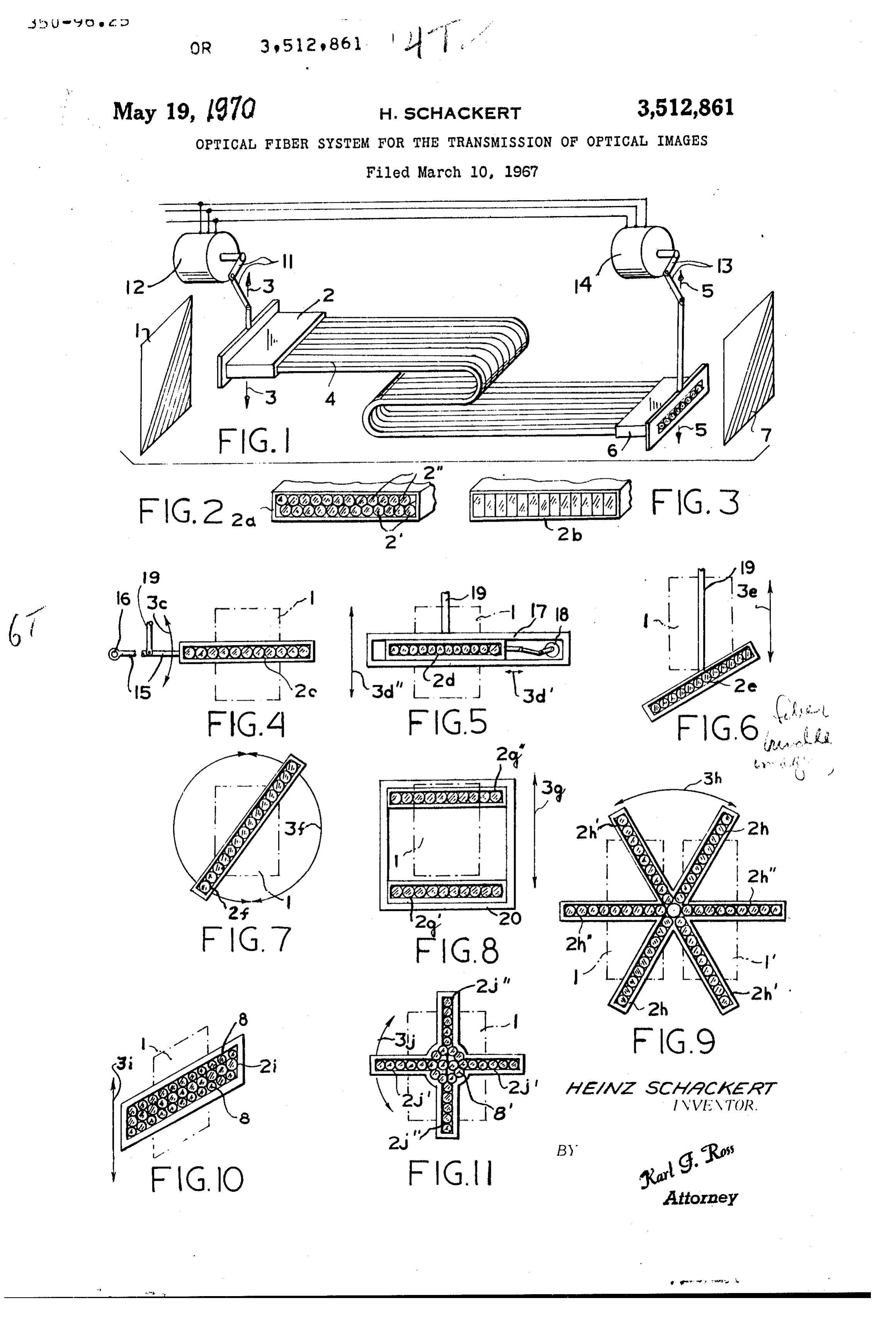
above and other features of my invention will medium for the visualization or recording of the trans become more fully apparent from the following descrip mitted information. tion of certain embodiments, reference being made to The use of a bundle of fiber-optical elements in the transmission of such images is advantageous in any situa 40 theFIG. accompanying drawing in which: 1 diagrammatically illustrates, in perspective view, tion in which the two surfaces do not confront each an image-transmission system comprising a flat bundle of other in such a manner that direct focusing of light rays from one surface upon the other by conventional project light-conductive fibers according to the invention; ing lenses and/or mirrors would be practical. Further theFIG. 2 is a perspective end view of a modification of fiber bundle of FIG. 1;
more, the piping of light through such fibers prevents 45 FIG. 3 is a view similar to FIG. 2 illustrating another interception of the message between the transmitting and receiving stations. Also, transposition of fibers in the modification; and
FIGS. 4-11 are diagrammatic views showing different bundle and/or variations in their relative spacing enables groupings of fibers and various modes of displacement the inversion or distortion of images as well as their magnification or reduction for purposes of coding, stand 50 thereof adapted to be used in the system of FIG. 1. The system illustrated in FIG. 1 comprises an image ardization, artistic effects and so forth. surface 1 and a receiving surface 7 optically interlinked by In prior systems of this type, however, it was neces sary to use as many light-conductive fibers in the bundle aofflat bundle 4 of the usual type of light-conductive fibers glass or synthetic resin. Bundle 4 has an input end 2 as there were discrete image elements to be transmitted, the number of these elements being determined by the which extends completely across surface 1 in one (here the horizontal) dimension and is reciprocable in another desired degree of resolution of the picture or message.
Thus, for example, a square surface of 20 x 20 mm. con (here vertical) dimension, as indicated by arrow 3, with tains one million image elements if the resolution is to the aid of a sweep mechanism shown as a crank drive 11 be 20p. powered by a motor 12. A similar sweep mechanism, com The general object of my invention is to provide a 60 put prising a crank drive 13 and a motor 14, engages the out method of and means for transmitting images with the aid end 6 of bundle 4 to move it across the vertical dimen of fiber-optical elements in a manner enabling the num sion of surface 7 as indicated by arrow 5. Motors 12 and ber of light-conductive fibers to be materially reduced 14 are synchronized and the strokes of their cranks 11 and without sacrificing any of the aforementioned advantages by 13 are identical so that a picture on surface 1, picked up of such systems. 85 the input end 2 of fiber bundle 4, will be reproduced to This object is realized, pursuant to my present inven scale on surface 7 by its illumination through the output tion, by the provision of a fiber bundle which has a flat end 6 of that bundle. If surface 7 is a photosensitive film or the like, the speed or drives 11 and 13 is not critical tened input end confronting an image surface and a (assuming the image on surface 1 to be stationary) and flattened output end confronting a receiving surface, each of these flattened ends extending preferably linearly over 70 aproduced single sweep may suffice for the reproduction; if the re image is to be observed visually, the sweep substantially the entire associated surface in one dimen should be rapid and repeated within the limits of retentive sion while occupying only a minor fraction of the sur
Page 3
3 In FIG. 11, finally, I show two intersecting arrays of ness of the human retina, similar to the frame scan of fiber ends 2i' and 2.j', similar to the arrangement of FIG. a television picture. If surface 7 is part of a motion-picture film, the change of frames should, of course, occur be 9 (but with an angular spacing of 90°); their reciprocating tween the sweeps. Sweep has been indicated by arrow 3i. Illuminating fila If it were desired to invert the picture appearing on ments 8 are clustered about the intersection and center
surface 7, the fibers in bundle 4 could be crossed over of Naturally, rotation of the the two rows of fibers 2i and 2j'.
various types of motion and relative between the two ends 2 and 6 while the cranks 11 and 13 are placed in diametrically opposite positions so as to positioning df the image-transmitting fibers shown in each operate 180° out of phase. of FIGS. 3-11 should also be duplicated, with the possible For a change of scale in the vertical dimension, the O exceptions noted above, on both ends of the filament effective length of cranks 11 and 13 should be different; bundle, yet the illuminating fibers 8, 8' illustrated in FIGS. in the horizontal dimension, a scale change can be brought 10 and 11 are to be omitted at the output end where they about by a spreading or bunching of the fibers at output would only interfere with the reproduction of the message. end 6 relative to input end 2. The motors 12, 14, 18 are to be considered as representa In FIG. 2 I have shown a modified input end 2a of 15 tive of any type of conventional mechanical, electrome chanical, magnetic, hydraulic or pneumatic means capable bundle 4 constituted by two closely adjacent rows of fiber of imparting the desired displacement to the associated ends 2 and 2', these rows being relatively staggered by one fiber radius to insure continuity of pickup over the Rand, ends; in some cases the fibers may also be moved by entire width of the image surface. It will be understood that the corresponding output end 6 (FIG. 1) should be 20 Features shown in FIGS. 2-11 may be combined or laid out in the same manner but that the relative position interchanged, within the limits of compatibility, without of the fibers between these two ends is immaterial. departing from the spirit and scope of my invention. In FIG. 3 I show another modification 2b of the input I claim:
end of the fiber bundle with the extremities of its filaments 1. A system for the transmission of optical images, deformed into rectangular shape, these extremities con 25 comprising means forming an image surface; means form tacting one another along adjoining sides of their squares ing a receiving surface remote from said image surface; so as to provide again a continuous pickup without the a bundle of light-conductive fibers disposed between said need for having more than one row of fibers. surfaces, said bundle having a flattened input end adjacent FIG. 4 shows the input end 2c mounted on the end of a said image surface and a flattened output end adjacent swingable arm 15 which oscillates about a fulcrum 16 30 said receiving surface, each of said flattened ends extend as indicated by arrow 3c. ing substantially entirely over the respective surface in one In FIG. 5 the input end 2d is horizontally slidable in dimension while occupying only a minor fraction of the a frame 17 under the control of a drive mechanism 18 Surface in a direction perpendicular thereto; a pair of elon imparting high-frequency oscillations to the fiber bundle, gate guide elements slidably engaging said flattened input as indicated by arrow 3d", in contradistinction to the rela and output ends, respectively, while extending in said one tively slow large-amplitude oscillations (arrow 3d') which dimension of the respective surface; and mechanism the assembly experiences by virtue of a mounting of frame coupled with said input and output ends for concurrently 17 on an arm 19 leading to the crank 11 of FIG. 1. The displacing same across their respective surfaces, said transverse oscillation (with reference to the crank-con 40 mechanism including synchronized but mutually inde trolled sweep) produced by drive means 18 should have pendent first and second main oscillatory drives respec a minimum amplitude of about one fiber diameter and a tively engaging said guide elements for moving same in frequency of at least in cycles per sweep where n is the said perpendicular direction and first and second ancillary number of fibers in the bundle. oscillatory drives on said guide elements engaging the In FIG. 6 the input end 2e, reciprocating vertically as respective fiber ends for superimposing transverse oscil indicated by arrow 3e, is inclined with reference to the 45 lations of Substantially higher frequency upon the motion horizontal so that its sweep occurs at other than right of said fiber ends due to said main oscillatory drives, said angles to its principal dimension. Also in this case, how bundle being flexible and of such length that its mid ever, the width of the bundle in the direction of its sweep portion remains substantially stationary as said ends are is only a small fraction of the corresponding dimension 50 oscillated.
of the confronting surface 1. 2. A system as defined in claim 1 wherein said main FIG. 7 shows the possibility of rotating the input end drives have different stroke lengths in said perpendicular of a fiber bundle 2f about the center of surface 1 as direction.
indicated by arrows 3f. 3. A system as defined in claim 1 wherein said main FIG. 8 shows the possibility of concurrently displacing drives are relatively dephased.
two transversely spaced fiber arrays 2g', 2g', mounted in 55 References Cited a common frame 20, as indicated by arrow 3g.
FIG. 9 shows a set of fiber arrays 2h, 2h', 2h' angularly UNITED STATES PATENTS intersecting one another with 60° spacing, the center of 3,204,543 9/1965 O'Keeffe --------- 350-96 X rotation (arrow 3h) being here offset from surface 1 in 2,939,362 6/1960 Cole ---------- 350-96 X contradistinction to the arrangement of FIG. 7. The fiber 60 3,016,785 1/1962 Kapany ------------ 350-96 arrays here need not oscillate through an angle greater 3,125,013 3/1964 Herricket al. 350-96 X than 60". This arrangement can also be used to scan a sec 3,125,812 3/1964 Simpson ----------- 350-96 X ond surface 1'. 3,192,843 7/1965 Kapany et al. ------- 350-96 X FIG. 10 shows an array of fiber ends 2i juxtaposed with 65 3,194,142 7/1965 Black ------------- 350-96 X extremities of other filaments 8 whose opposite ends are 3,238,837 3/1966 Woodcock -------- 350-96 illuminated from a source not shown, the entire assembly being reciprocable across surface 1 as indicated by arrow DAVID H. RUBIN, Primary Examiner 3i. This arrangement is particularly useful where surface 1 is not luminous so that it has to be lit by incident radia 70 U.S. C., X.R, tion here supplied by the filaments 8, 355-1
Provenance
- Collection
- Cited prior art
- Original PDF
- patentimages.storage.googleapis.com →
- Filed
- 1967-03-10
- Pages
- 3
- Method
- pdftotext (the PDF's own text layer) + pdftoppm 300dpi page scans
- Source
- Google Patents bibliographic record
- Granted
- 1970-05-19
- Inventors
- Heinz Schackert; Jos Schneider Optische Werke GmbH
- Transcribed from
- patentimages.storage.googleapis.com →