patent · US4570063
Device for the optical scanning of a document
11 February 1986
Page 1 — bibliographic record
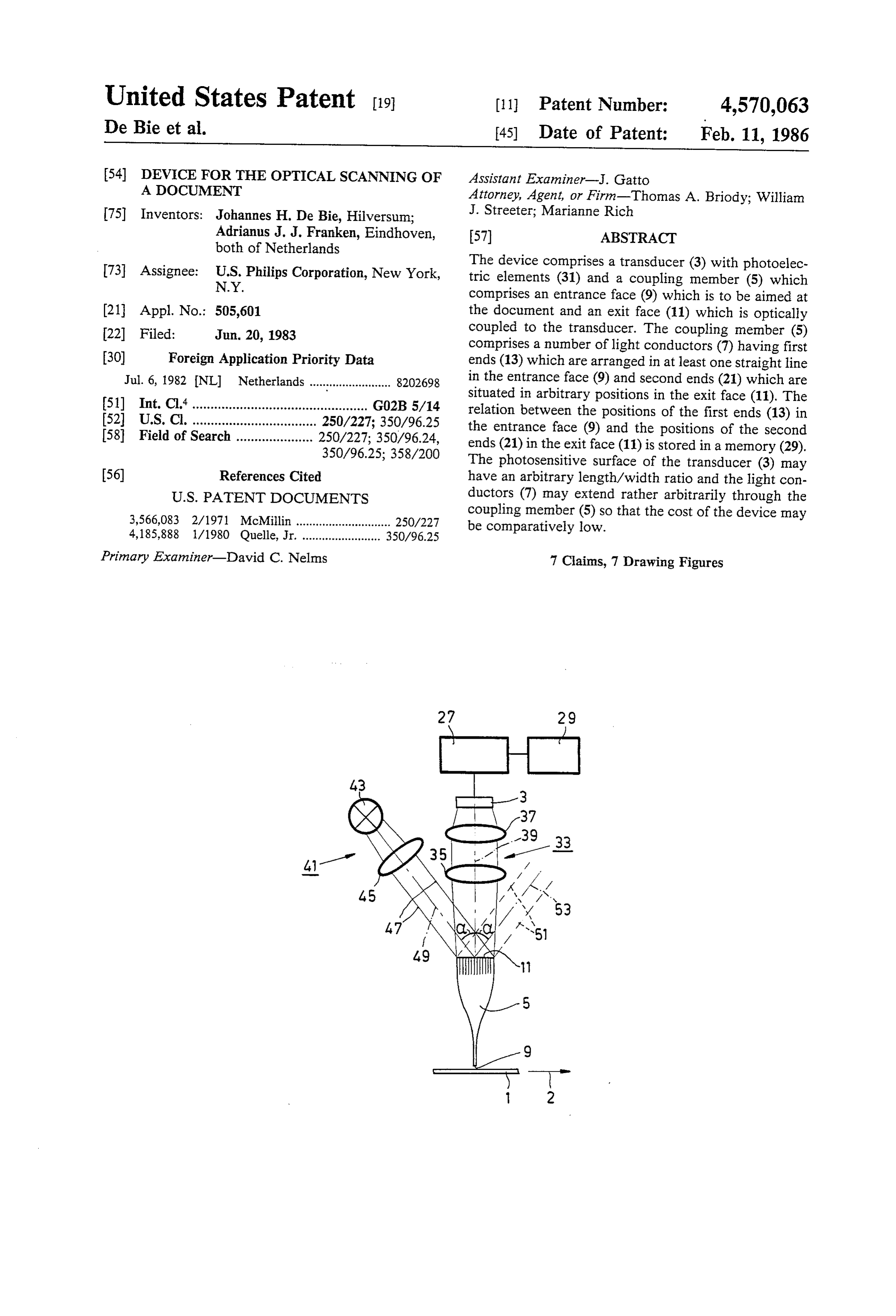
United States Patent (19) 11 Patent Number: 4,570,063 De Bie et al. (45) Date of Patent: Feb. 11, 1986 (54) DEVICE FOR THE OPTICAL SCANNING OF Assistant Examiner-J. Gatto A DOCUMENT Attorney, Agent, or Firm-Thomas A. Briody; William 75 Inventors: Johannes H. De Bie, Hilversum; J. Streeter; Marianne Rich Adrianus J. J. Franken, Eindhoven, 57) ABSTRACT both of Netherlands 73 Assignee: U.S. Philips Corporation, New York, The device comprises a transducer (3) with photoelec N.Y. tric elements (31) and a coupling member (5) which comprises an entrance face (9) which is to be aimed at (21) Appl. No.: 505,601 the document and an exit face (11) which is optically 22 Filed: Jun. 20, 1983 coupled to the transducer. The coupling member (5) comprises a number of light conductors (7) having first (30) Foreign Application Priority Data ends (13) which are arranged in at least one straight line Jul. 6, 1982 NL Netherlands ......................... 8202698 in the entrance face (9) and second ends (21) which are situated in arbitrary positions in the exit face (11). The 51) Int. Cl. ................................................ GO2B 5/14 relation between the positions of the first ends (13) in (52) U.S. Cl. .................................. 250/227; 350/96.25 the entrance face (9) and the positions of the second 58 Field of Search ..................... 250/227; 350/96.24, ends (21) in the exit face (11) is stored in a memory (29). 350/96.25; 358/200 The photosensitive surface of the transducer (3) may 56) References Cited have an arbitrary length/width ratio and the light con
coupling member (5) so that the cost of the device may 3,566,083 2/1971 McMillin ...... a ---- - - - - 250/227 4,185,888 1/1980 Quelle, Jr. ........................ 350/96.25 be comparatively low.
Primary Examiner-David C. Nelms 7 Claims, 7 Drawing Figures
Page 2
Drawing sheet — no readable text.
Page 3
Drawing sheet — no readable text.
Page 4
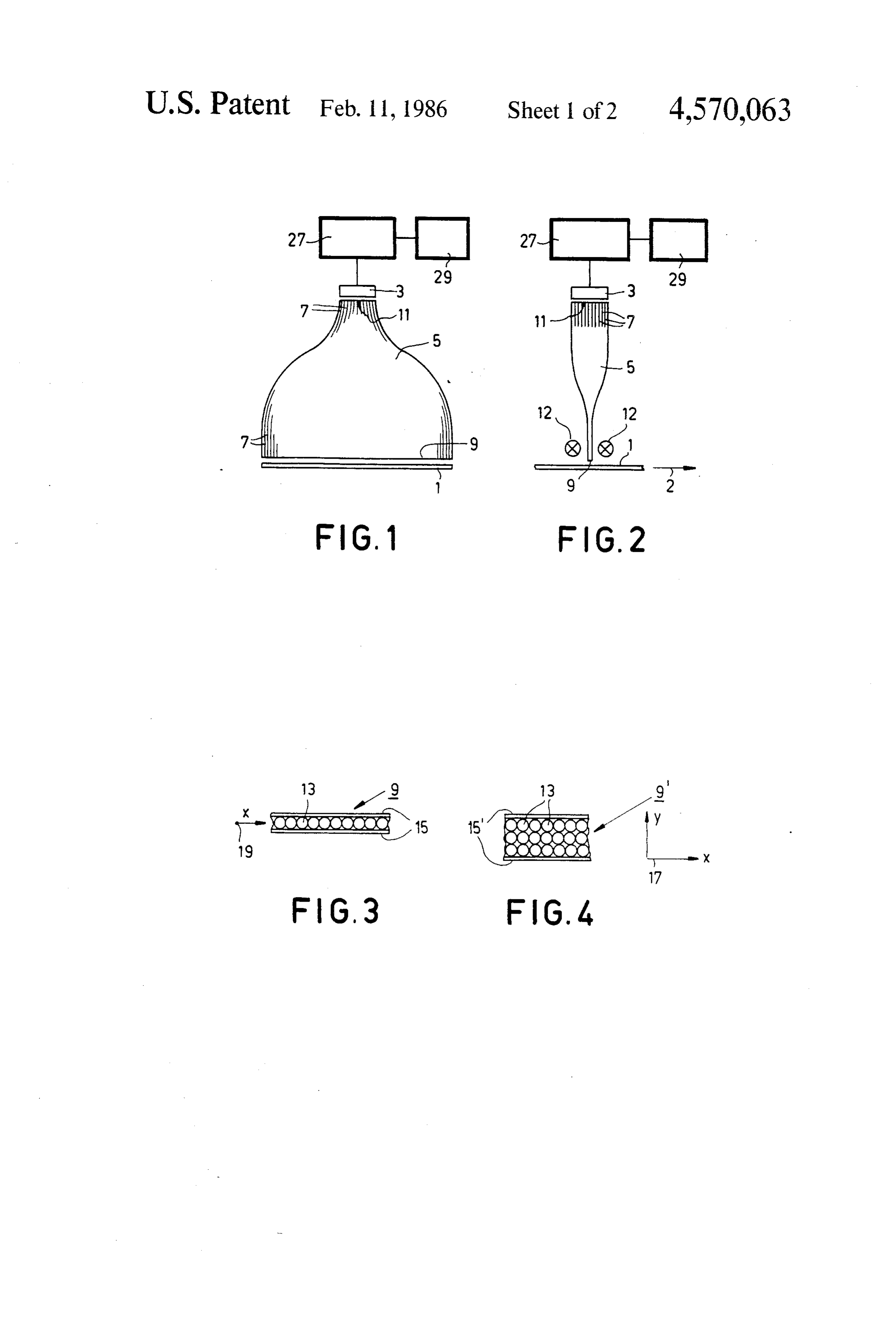
DEVICE FOR THE OPTICAL SCANNING OF A BRIEF DESCRIPTION OF THE DRAWING DOCUMENT The invention will be described in detail hereinafter with reference to the drawing. Therein:
FIG. 1 is a diagrammatic front view of a first embodi 1. Field of the Invention ment of a device in accordance with the invention; The invention relates to a device for the optical scan FIG. 2 is a diagrammatic side elevation of the device ning of a document, comprising a transducer with pho shown FIG.
in FIG. 1;
3 shows a part of a first embodiment of an en toelectric elements and a coupling member which com O trance face of a coupling member; prises an entrance face which is to be aimed at the docu ment and an exit face which is optically connected to entrance face of aa coupling
FIG. 4 shows part of a second embodiment of an member;
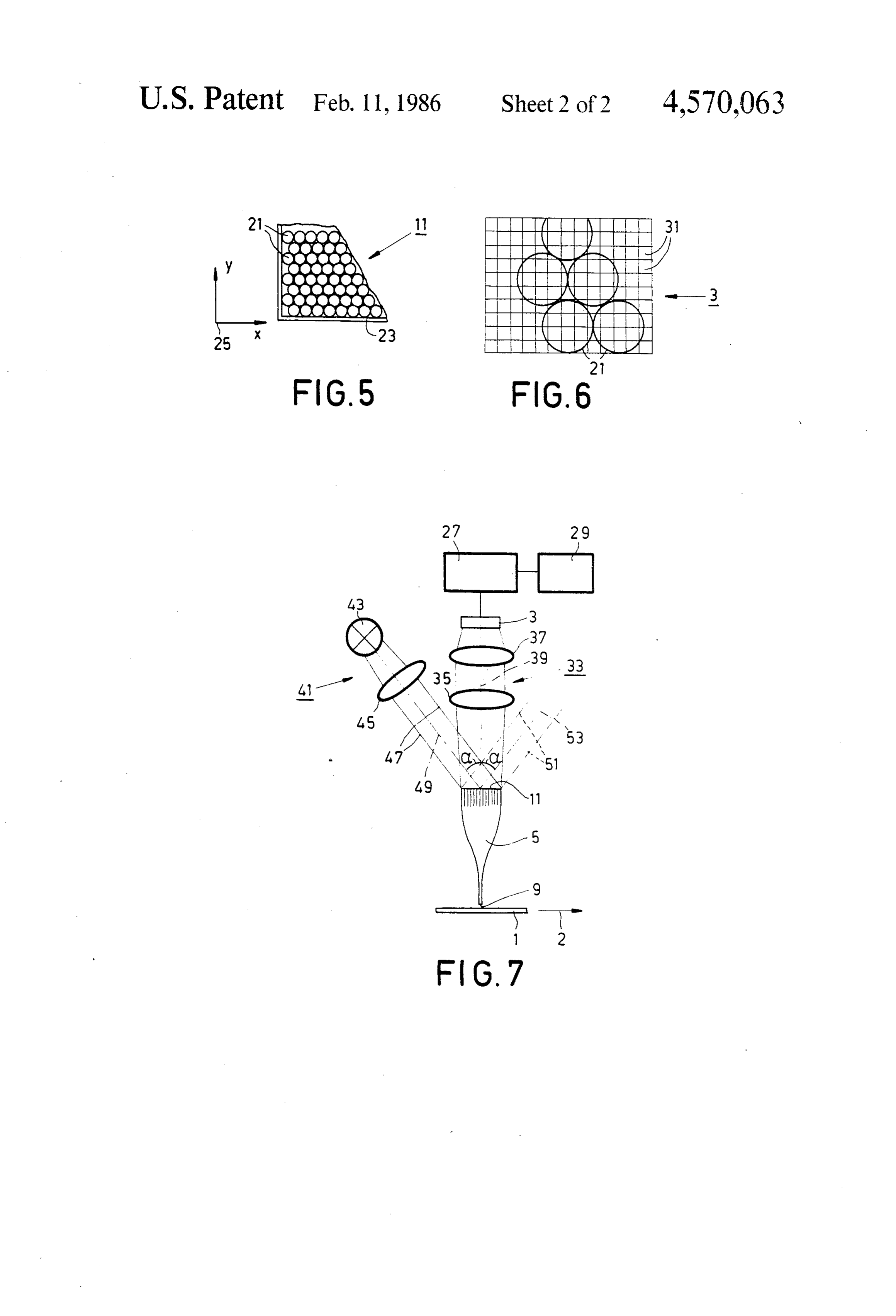
the transducer, said coupling member comprising a FIG. 5 shows an embodiment of an exit face of a plurality of light conductors which extend from the coupling member;
entrance face to the exit face and whose first ends are 15 FIG. 6 diagrammatically shows a part of the exit face arranged in at least one line in the entrance face. together with a part of a transducer; and 2. Description of the Prior Art FIG. 7 is a diagrammatic side elevation of a second A device of this kind of known from U.S. Pat. No. embodiment of a device in accordance with the inven 3,318,996. The transducer thereof consists of a large 20 tion.
number of photoelectric elements which are arranged in DESCRIPTION OF THE PREFERRED a straight line. Such transducers have a very large EMBODIMENTS length-to-width ratio, are comparatively expensive, and are often not available in the desired length. The light theFIGS. 1 and 2 diagrammatically show a device for optical scanning of a document 1 (for example, a conductors must be accurately positioned with respect 25 sheet of paper having the format A4 which is moved in to one another in the coupling member; this is a time the direction of the arrow 2 by means of a known trans consuming and hence expensive operation. port device which is not shown) which comprises a SUMMARY OF THE INVENTION transducer 3 with photoelectric elements and a coupling member 5 which comprises a number of light conduc
It is an object of the invention to provide a device of 30 tors 7. The coupling member 5 comprises an entrance the kind set forth in which the transducer may have an face 9 which faces the document 1 and an exit face 11 arbitrary length-to-width ratio which may even amount which is optically connected to the transducer 3 in that to approximately 1, if desired, and in which the light it is positioned against the transducer or at a very short conductors may extend more or less at random through distance therefrom, if desired, with an intermediate the coupling member, so that the cost of the transducer 35 layer of transparent cement or a lens (not shown). For as well as that of the coupling member may be compara the illumination of the document 1, an elongate light tively low. source 12, for example, a tubular lamp (omitted in FIG. To this end, the device in accordance with the inven 1 for the sake of clarity) is arranged near the entrance tion is characterized in that the second ends of the light 40 face 9 on both sides of the coupling member 5. Alterna conductors are situated in arbitrary positions in the exit tively, a light source may be arranged underneath the face of the coupling member, the device comprising a document 1.
memory in which the relation existing between the 9 toThethelight conductors 7 extend from the entrance face exit face 11, their first ends being arranged in positions of the first ends in a system of coordinates one or more straight lines in the entrance face whilst associated with the entrance face and the positions of 45 their second ends the second ends in a system of coordinates associated the exit face whichareis arranged preferably in arbitrary positions in filled in a dense pack with the exit face, is stored. ing. FIGS. 3 and 4 show two feasible arrangements of After combination of the coupling member and the the first ends in the entrance face, and FIG. 5 shows a transducer, this relation can be readily established, for feasible arrangement of the second ends in the exit face. example, by successively illuminating all first ends of 50 FIG. 3 shows a part of the entrance face 9 in which the light conductors and by determining each time the first ends 13 of the light conductors 7 are arranged which photoelectric elements produce an output signal in a single straight line. The first ends 13 are arranged so in reaction thereto. This information can be stored in that they contact one another and intercept a maximum the memory, for example, a programmable read-only amount of light from the document 1. They are retained memory (PROM). 55 in a mount 15 in which they can be secured by means of A preferred embodiment of the device in accordance cement.
with the invention is characterized in that the surface entrance FIG. 4 shows a part of a further embodiment 9" of the area of the second end of a light conductor amounts to face in which the first ends 13 of the light a multiple of the photosensitive surface area of a photo 60 conductors 7 are arranged in three parallel straight electric element. Each second end thus exposes an asso lines. In this embodiment the first ends 13 are again arranged so that they contact one another. They are ciated group of photoelectric elements in this embodi retained ment, so that the relevant first end wherefrom this light ends 13 inis adesiredmount 15'. If a denser packing of the first (enabling scanning with a higher originates can be identified with certainty.
The surface area of the transducer is economically 65 shifted to the left or theoneright resolution), the central of the three lines may be over a distance which used in a further preferred embodiment which is char corresponds to half the diameter of the first ends. If acterized in that the second ends of the light conductors desired, the number of lines in which the first ends 13 fill the exit face in a dense packing. are arranged may be chosen to be so large that the
Page 5
surface area of the entrance face 9' equals the surface established with certainty which second end emits light. area of the document 1 to be scanned. In that case the Even though there are photoelectric elements 31 which document need not be transported in the direction of can be exposed by two or three second ends 21, with the arrow 2 during scanning. The position of each first each second end there are always associated some pho end 13 in the entrance face 9' can be indicated in an 5 toelectric elements which cannot be exposed by any orthogonal system of coordinates 17 which is associated other second end. The output signals of the photoelec with the entrance face and which comprises an X-axis tric elements 31 associated with a second end 21 are and a Y-axis. For the embodiment shown in FIG. 3, a preferably added in order to obtain a high output signal. one-dimensional system of coordinates 19 which con The rectangular pattern of photoelectric elements 31 is prises only an X-axis suffices. O usually electronically scanned line-wise as is common FIG. 5 shows a part of an embodiment of the exit face practice in transducers for picking-up television pic 11. The second ends 21 of the light conductors 7 are tures. Because each second end 21 cooperates with a arranged in the exit face 11 in a dense packing (hexago plurality of lines, the scanning of, for example, all lines nal densest circular packing) so that they fill the exit bearing an even sequence number may be omitted with face as well as possible. They are retained in a mount 23. 15 out information being lost. The scanning speed of the The position of each second end 21 in the exit face 11 transducer can thus be substantially increased. More can be indicated in an orthogonal system of coordinates over, no information will be lost should a small number 25 which is associated with the exit face and which of photoelectric elements 31 which are distributed comprises an X-axis and a Y-axis. across the transducer 3 become faulty. Consequently, The transducer 3 is connected to a signal processing 20 the quality requirements imposed on the transducer 3 device 27 (see FIGS. 1 and 2) which comprises an am may be less severe than those imposed on a transducer plifier for the amplification of the signals supplied by for picking up television pictures. Severe requirements the photoelectric elements and which also comprises a need not be imposed either on the quality of any lens register for the storage of these signals so that they can arranged between the exit face 11 and the transducer, be applied in the correct sequence to a further device, 25 because imaging faults do not cause a loss of informa for example, a printer or a fascimile transmitter (not tion either.
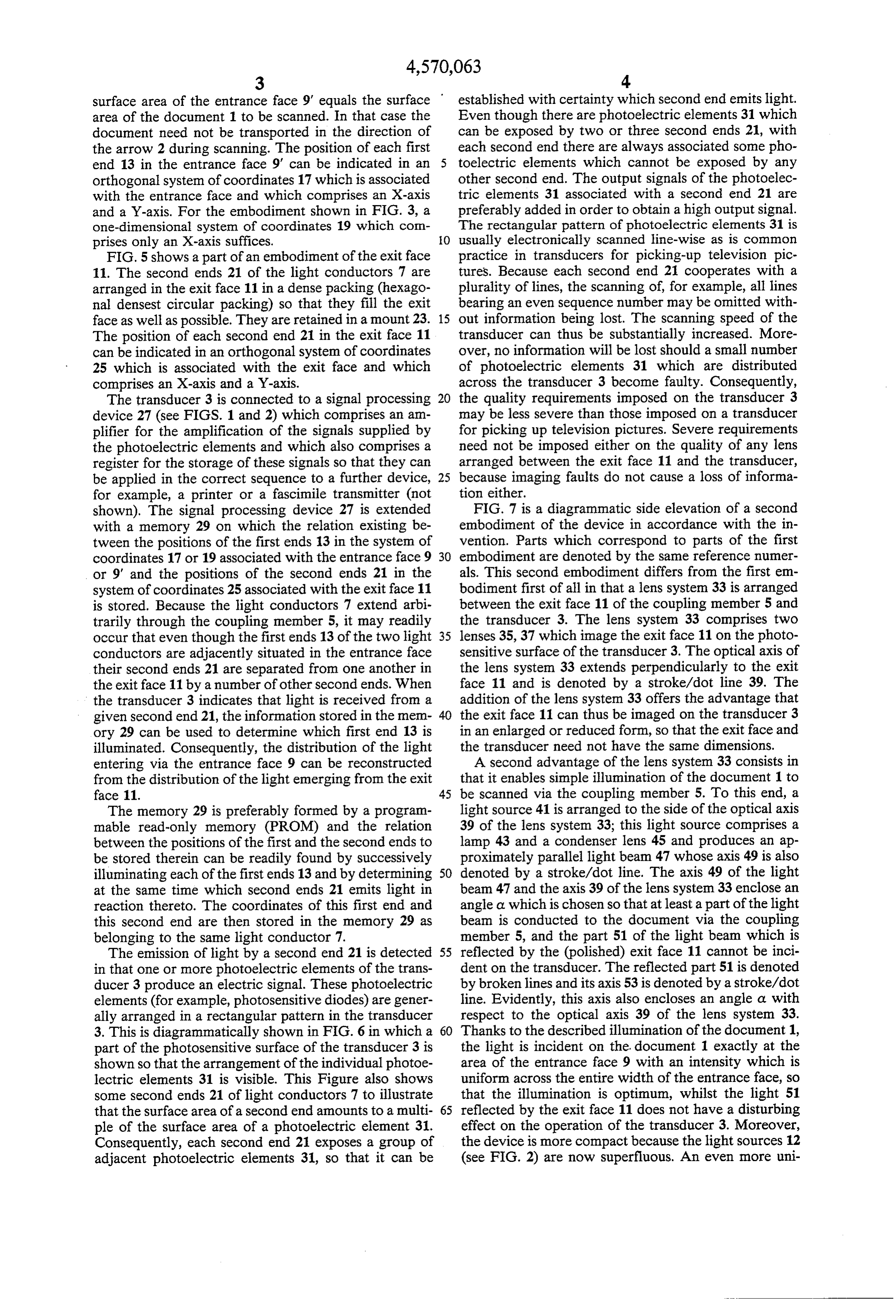
shown). The signal processing device 27 is extended FIG. 7 is a diagrammatic side elevation of a second with a memory 29 on which the relation existing be embodiment of the device in accordance with the in tween the positions of the first ends 13 in the system of vention. Parts which correspond to parts of the first coordinates 17 or 19 associated with the entrance face 9 30 embodiment are denoted by the same reference numer or 9' and the positions of the second ends 21 in the als. This second embodiment differs from the first em system of coordinates 25 associated with the exit face 11 bodiment first of all in that a lens system 33 is arranged is stored. Because the light conductors 7 extend arbi between the exit face 11 of the coupling member 5 and trarily through the coupling member 5, it may readily the transducer 3. The lens system 33 comprises two occur that even though the first ends 13 of the two light 35 lenses 35, 37 which image the exit face 11 on the photo conductors are adjacently situated in the entrance face sensitive surface of the transducer 3. The optical axis of their second ends 21 are separated from one another in the lens system 33 extends perpendicularly to the exit the exit face 11 by a number of other second ends. When face 11 and is denoted by a stroke/dot line 39. The the transducer 3 indicates that light is received from a addition of the lens system 33 offers the advantage that given second end 21, the information stored in the mem 40 the exit face 11 can thus be imaged on the transducer 3 ory 29 can be used to determine which first end 13 is in an enlarged or reduced form, so that the exit face and illuminated. Consequently, the distribution of the light the transducer need not have the same dimensions. entering via the entrance face 9 can be reconstructed A second advantage of the lens system 33 consists in from the distribution of the light emerging from the exit that it enables simple illumination of the document 1 to face 11. 45 be scanned via the coupling member 5. To this end, a The memory 29 is preferably formed by a program light source 41 is arranged to the side of the optical axis mable read-only memory (PROM) and the relation 39 of the lens system 33; this light source comprises a between the positions of the first and the second ends to lamp 43 and a condenser lens 45 and produces an ap be stored therein can be readily found by successively proximately parallel light beam 47 whose axis 49 is also illuminating each of the first ends 13 and by determining 50 denoted by a stroke/dot line. The axis 49 of the light at the same time which second ends 21 emits light in beam 47 and the axis 39 of the lens system 33 enclose an reaction thereto. The coordinates of this first end and angle a which is chosen so that at least a part of the light this second end are then stored in the memory 29 as beam is conducted to the document via the coupling belonging to the same light conductor 7. member 5, and the part 51 of the light beam which is The emission of light by a second end 21 is detected 55 reflected by the (polished) exit face 11 cannot be inci in that one or more photoelectric elements of the trans dent on the transducer. The reflected part 51 is denoted ducer 3 produce an electric signal. These photoelectric by broken lines and its axis 53 is denoted by a stroke/dot elements (for example, photosensitive diodes) are gener line. Evidently, this axis also encloses an angle a with ally arranged in a rectangular pattern in the transducer respect to the optical axis 39 of the lens system 33. 3. This is diagrammatically shown in FIG. 6 in which a Thanks to the described illumination of the document 1, part of the photosensitive surface of the transducer 3 is the light is incident on the document 1 exactly at the shown so that the arrangement of the individual photoe area of the entrance face 9 with an intensity which is lectric elements 31 is visible. This Figure also shows uniform across the entire width of the entrance face, so some second ends 21 of light conductors 7 to illustrate that the illumination is optimum, whilst the light 51 that the surface area of a second end amounts to a multi 65 reflected by the exit face 11 does not have a disturbing ple of the surface area of a photoelectric element 31. effect on the operation of the transducer 3. Moreover, Consequently, each second end 21 exposes a group of the device is more compact because the light sources 12 adjacent photoelectric elements 31, so that it can be (see FIG. 2) are now superfluous. An even more uni
Page 6
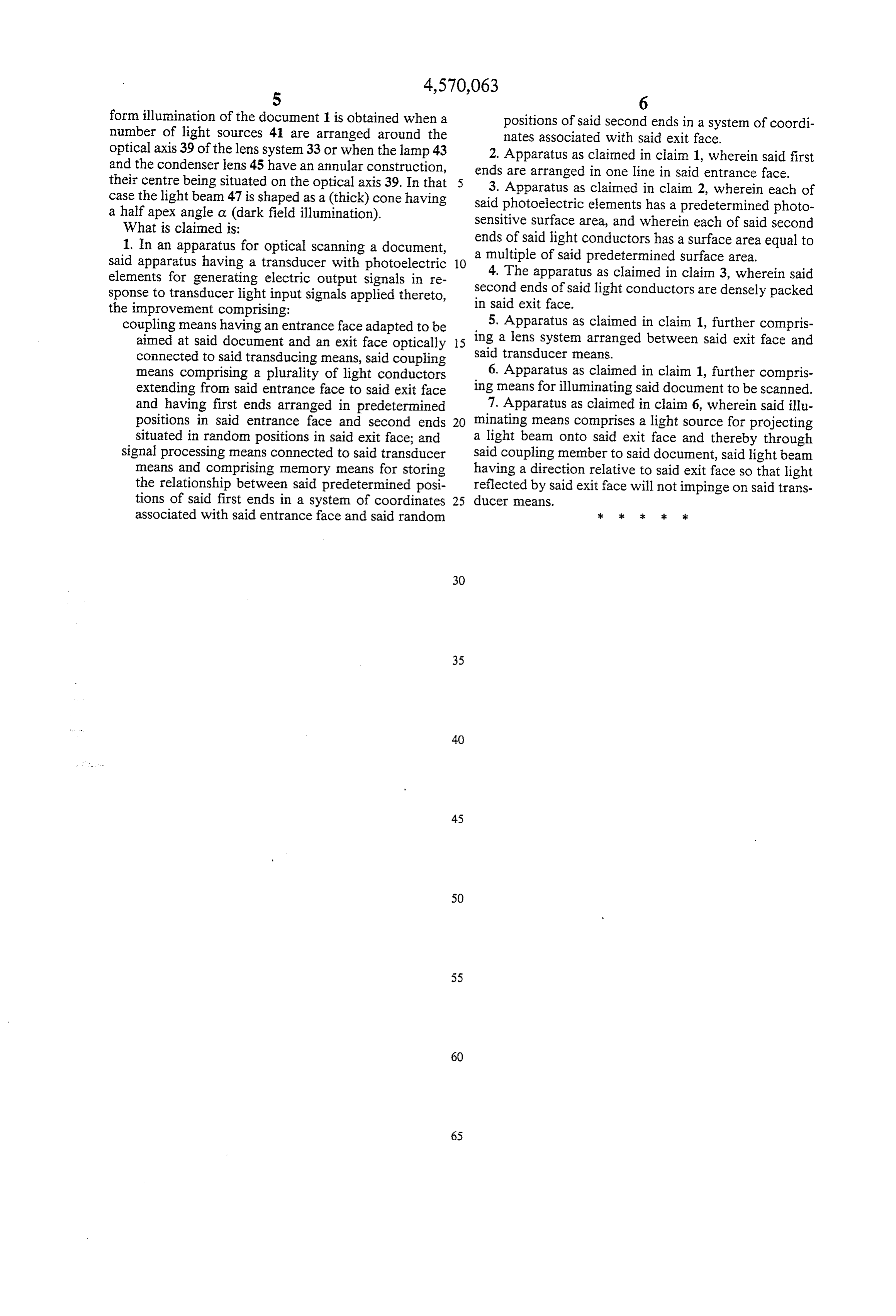
form illumination of the document 1 is obtained when a positions of said second ends in a system of coordi number of light sources 41 are arranged around the nates associated with said exit face. optical axis 39 of the lens system 33 or when the lamp 43 2. Apparatus as claimed in claim 1, wherein said first and the condenser lens 45 have an annular construction, ends are arranged in one line in said entrance face. their centre being situated on the optical axis 39. In that case the light beam 47 is shaped as a (thick) cone having said photoelectricas elements 3. Apparatus claimed in claim 2, wherein each of has a predetermined photo a half apex angle a (dark field illumination). sensitive surface area, and wherein each of said second What is claimed is:
1. In an apparatus for optical scanning a document, ends of said light conductors has a surface area equal to said apparatus having a transducer with photoelectric 10 a multiple of said predetermined surface area. 4. The apparatus as claimed in clain 3, wherein said elements for generating electric output signals in re sponse to transducer light input signals applied thereto, insecond ends of said light conductors are densely packed the improvement comprising: said exit face.
coupling means having an entrance face adapted to be 5. Apparatus as claimed in claim 1, further compris aimed at said document and an exit face optically 15 ing a lens system arranged between said exit face and connected to said transducing means, said coupling said transducer means.
means comprising a plurality of light conductors 6. Apparatus as claimed in claim 1, further compris extending from said entrance face to said exit face ing means for illuminating said document to be scanned. and having first ends arranged in predetermined 7. Apparatus as claimed in claim 6, wherein said illu positions in said entrance face and second ends 20 minating means comprises a light source for projecting situated in random positions in said exit face; and a light beam onto said exit face and thereby through signal processing means connected to said transducer said coupling member to said document, said light beam means and comprising memory means for storing having a direction relative to said exit face so that light the relationship between said predetermined posi reflected by said exit face will not impinge on said trans tions of said first ends in a system of coordinates 25 ducer means.
associated with said entrance face and said random : ck ck ck
Provenance
- Collection
- Cited prior art
- Original PDF
- patentimages.storage.googleapis.com →
- Filed
- 1983-06-20
- Pages
- 6
- Method
- pdftotext (the PDF's own text layer) + pdftoppm 300dpi page scans
- Source
- Google Patents bibliographic record
- Granted
- 1986-02-11
- Inventors
- Johannes H. De Bie; Adrianus J. J. Franken; US Philips Corp
- Transcribed from
- patentimages.storage.googleapis.com →