patent · US3128167
Method and apparatus for forming tapered fiber optical image transfer devices
7 April 1964
Page 1
x 3,28, CROSS REFERENCE SEARCH ROOM
April 7, 1964 R. F. WOODCOCK 3,128,167 : vi" ". S- ---
METHOD AND APPARATUS FOR FORMING TAPERED FIBER
OPTICAL IMAGE TRANSFER DEVICES
Filed Nov. 28, 1960 3. Sheets-Sheet
ZZZŽ)
AfCHA2D A WOODCOCAC
ATTOeNEys
Page 2
Drawing sheet — no readable text.
Page 3
Drawing sheet — no readable text.
Page 4
United States Patent Office 3,128,167. Patented Apr. 7, 1964
al areas at opposite ends and which have respective por 3,128,167 tions intermediate their ends of a cross-sectional area METHOD AND APPARATUS FOR FORMING larger than would be found in straight-sided or straight TAPERED FIBER OPTICAL MAGE TRANS. tapered members having ends of said cross-sectional areas.
FEER DEVICES
Richard F. Woodcock, South Woodstock, Conn., assignor The light-conducting members can comprise individual to American Optical Company, Southbridge, Mass, a light-conducting rods or fibers having respective light voluntary association of Massachusetts insulating coatings, but preferably comprise multifibers or Filed Nov. 28, 1960, Ser. No. 72,189 small fiber bundles embodying a multiplicity of light-con 10 Claims. (C. 65-36) ducting fibers having respective light-insulating coatings which are fused together in vacuum-tight relation. For
The field of this invention is that of tapered fiber-optical O example, in the preferred method of this invention, there image-transfer devices such as might be used in magnify is provided a plurality of identical, tapered, light-conduct ing and demagnifying optical images, and the invention ing members each embodying a multiplicity of tapered relates, more particularly, to novel and improved methods light-conducting fibers having respective light-insulating and apparatus for manufacturing such devices. coatings which are fused together in side-by-side bundled Tapered fiber-optical image-transfer devices are well relation, each of said members having an end of rela known and have frequently been used as image-magnify tively large cross-sectional area and an opposite end of ing or demagnifying faceplates in cathode-ray tubes and relatively small cross-sectional area and tapered there the like, each such device embodying a plurality of tapered between at a rate of taper which increases at least at light-conducting fibers which are usually fused together one point intermediate said ends. in side-by-side, vacuum-tight relation. In such devices, 20 Another step of the method of this invention com each fiber is adapted to receive light at one end from a prises the provision of a mold having a tapered recess or portion of an optical image projected upon one end of aperture therein, the mold recess or aperture preferably the device and is adapted to conduct said light there tapering downwardly and inwardly. The light-conducting through for reproducing said image portion at the other 25 members are assembled in side-by-side relation within the end of the device, the difference in cross-sectional area of mold recess or aperture to form a bundle in which adja the tapered fibers at opposite ends thereof providing mag cent light-conducting members initially contact each nification or demagnification of respective image por other at points of said convexity and in which peripheral tions so that the fibers cooperate to magnify or demagnify members in the bundle initially contact tapered portions the entire image. At the present time, tapered image 30 of the mold at points of said convexity. In this arrange transfer devices of this sort are prepared by heating one ment, the light-conducting members can form a self-Sup end of a bundle of light-conducting fibers to a fusing porting dome extending across the mold recess or aper temperature and by drawing the bundle from said end at ture, each of the members being supported by line or point selected speed so that a section of the bundle is tapered as contact of points of convexity on said member with a whole for tapering individual fibers within the section similar points of convexity of adjacent members or with and for fusing the fiber together within said section. tapered portions of the mold.
However, the tapered faceplates and the like which can be According to this method, the light-conducting mem formed by this method are relatively limited in size in bers can be heated to a fusing temperature within said that the uniform heating of a localized area of a fiber mold recess or aperture. In one embodiment of the bundle in the manner required for drawing a tapered 40 method of this invention, the light-conducting members bundle section is difficult or impossible to achieve through can be heated to a relatively high fusing temperature for out a bundle of relatively large cross-sectional area. causing at least some of the members to sag further into It is an object of this invention to provide novel and the mold recess in the direction of the recess taper so that improved methods and apparatus for forming tapered the members are first fused together at said points of fiber-optical image-transfer devices; to provide methods initial contact, that is at said points of convexity, and and apparatus for forming such devices which are of rela are then fused together progressively along the lengths tively large cross-sectional area; to provide methods and of the members from said points of convexity. In this apparatus for forming such devices by securing a plurality arrangement, progressive fusing of the members out of smaller, individually-tapered members in side-by-side wardly from points of initial contact tends to sweep air bundled relation; to provide methods and apparatus for and other gases from between the members and prevents forming such devices by fusing a plurality of smaller, the formation and entrapment of air bubbles and the like individually-tapered inhage-transfer members in side-by between the fused members. In an alternative embodi side bundled relation without entrapment of air bubbles ment of the method of this invention, the light-conducting and the like between said smaller members; to provide members assembled within the mold aperture can be methods and apparatus for forming such devices which heated to a fusing temperature, preferably slightly lower are of relatively large cross-sectional area in which indi than described above, and axial pressure can be applied vidual light-conducting members embodied in the devices to the members for moving the members further into the are adapted to provide substantially the same degree of mold recess or aperture in the direction of the mold taper. image magnification and demagnification over the entire In this arrangement, the members are also initially fused cross-sectional area of the device; to provide methods 60 together at points of said convexity and are then fused and apparatus for economically forming tapered fiber together progressively along the lengths of the members optical image-transfer devices; and to provide such from said points of convexity. In a further alternative method and apparatus by which said devices can be rapidly embodiment of the method of this invention, the light and conveniently manufactured.
Briefly described, the novel and improved method pro 65 conducting members assembled within the mold aperture vided by this invention for forming tapered fiber-optical can be secured together adjacent the smaller end of the image-transfer devices includes the step of providing a mold recess or aperture and can be drawn further into the plurality of light-conducting members each of which has mold aperture for also fusing said members together in a slight convexity or entasis intermediate its ends. That the manner above described.
is, one step of said method comprises the provision of a 70 After fusing the light-conducting members into an in plurality of light-conducting members, preferably of tegrated unit, the unit can be permitted to cool and can tapered configuration, which are of selected cross-section be cut transversely of the members at each end of the
Page 5
unit, if desired, for forming light-receiving faces thereon, said detailed description referring to the drawings in and said faces can be optically finished for rendering them which:
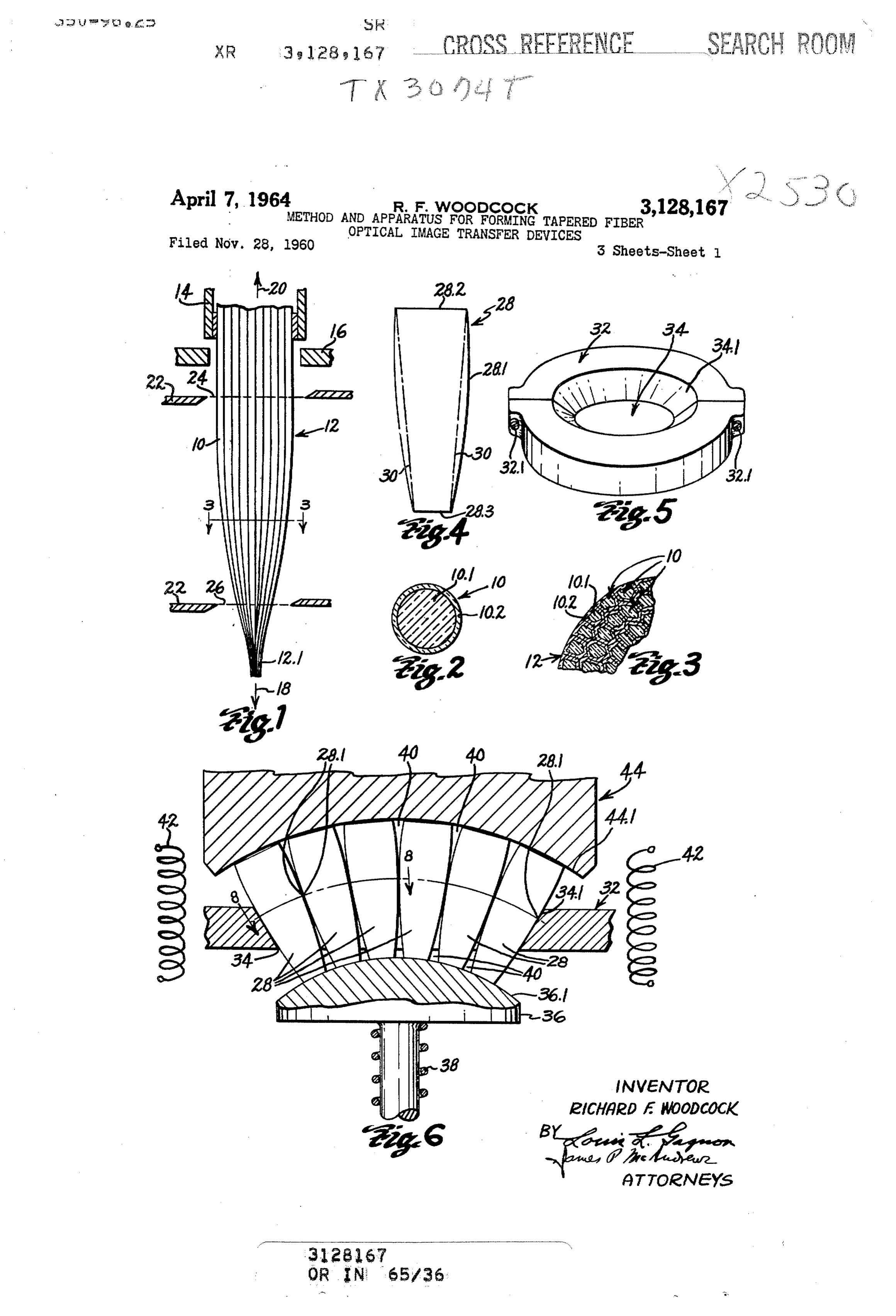
readily receptive to light. FIG. 1 is a diagrammatic view illustrating the forma The novel and improved apparatus provided by this tion of a tapered light-conducting member utilized in the invention includes a mold having a tapered recess or method provided by this invention; aperture therein, the mold recess or aperture preferably FIG. 2 is an enlarged transverse section view of a light extending downwardly and inwardly and being adapted conducting fiber embodied in the light-conducting mem to receive a plurality of light conducting members therein. ber of F.G. 1;
The apparatus preferably also includes a support which is FIG. 3 is a partial section view along line 3-3 of adapted to extend across at least a substantial part of said O FIG. 1;
moid recess or aperture for engaging light-conducting FIG. 4 is a side elevation view of the light-conducting members which are inserted within the mold recess or member of FIG. 1;
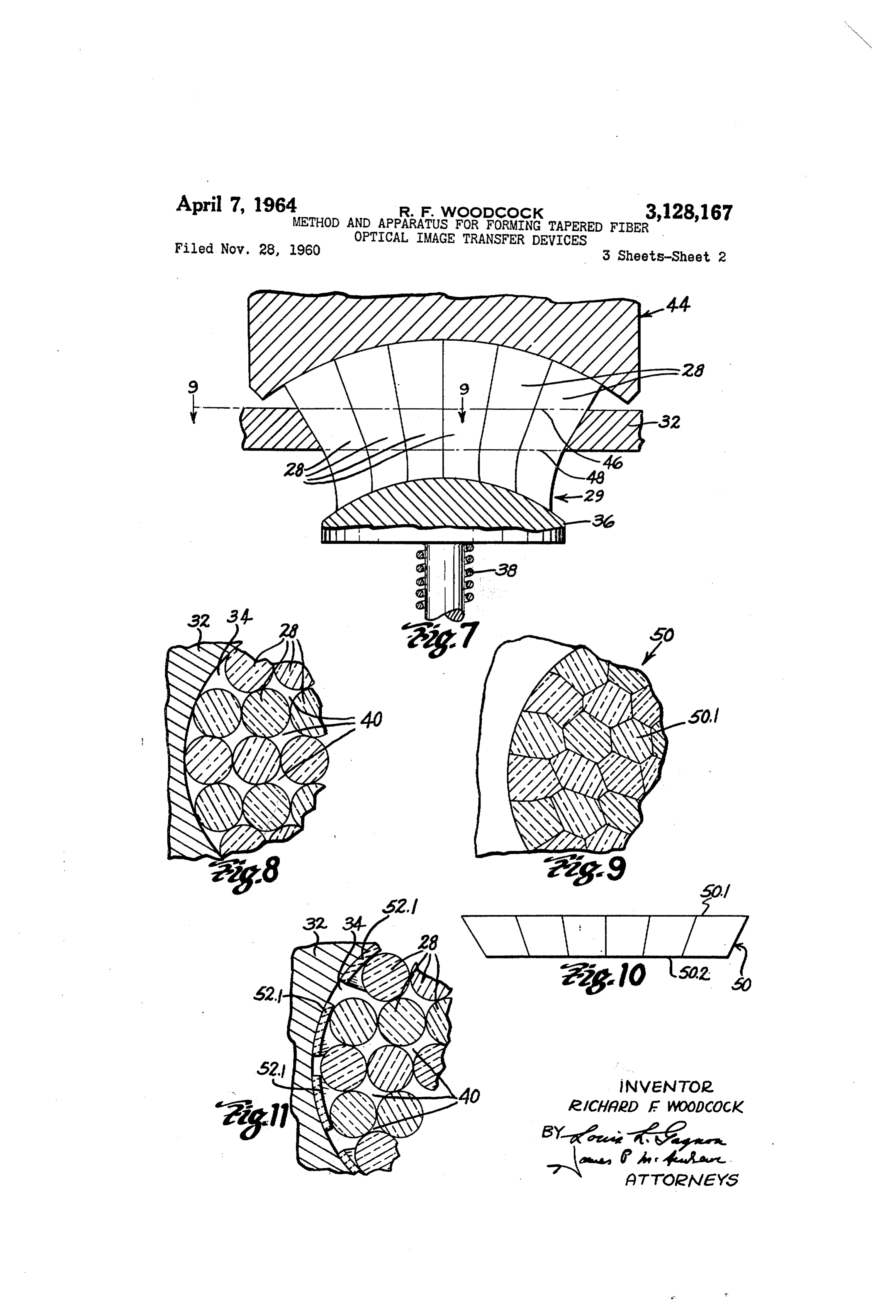
aperture through the larger end thereof, the support pref FIG. 5 is a perspective view at reduced scale of a mold erably being adapted to be retracted from said engage utilized in the method of this invention; ment. Alternatively, the support can be resiliently FIG. 6 is a partial vertical section view of the apparatus mounted to be adapted for movement in the direction of of this invention illustrating a step in one embodiment Said mold taper when pressure is applied thereto. The of the method of this invention; apparatus also includes means for heating the light-con FIG. 7 is a view similar to FIG. 6 illustrating a Subse ducting members within the mold, and preferably includes quent step in the method shown in FIG. 6; means for forcing the members to move further into the 20 FIG. 8 is a partial section view along line 8-8 of mold aperture. For example, said means for forcing the FIG. 6;
members to move into the aperture can comprise means FIG. 9 is a partial section view along line 9-9 of for applying axial pressure to the light-conducting mem FIG. 7;
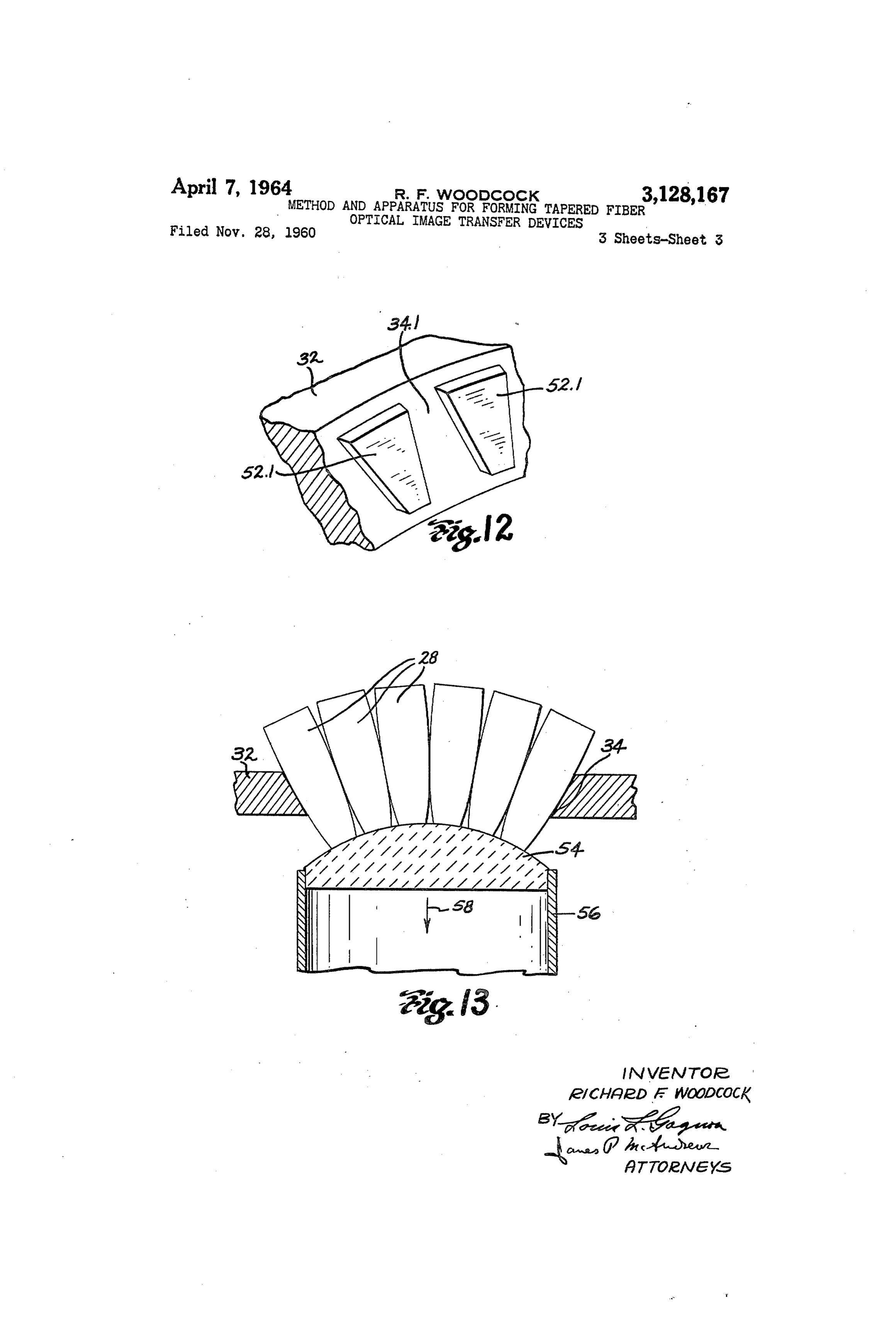
bers for pressing the members into the mold recess in FIG. 10 is a side elevation view of the device pro the direction of the mold taper or can comprise means for 25 vided by the method illustrated in FIGS. 1-9; drawing the members further into the mold recess. FIG. 11 is a view similar to FIG. 8 illustrating an al In this arrangement, a plurality of light-conducting ternative embodiment of the apparatus of this invention; members each of which has a slight convexity intermedi FIG. 12 is a partial perspective view of the apparatus ate its ends can be inserted within the mold recess or shown in FIG. 11; and aperture in side-by-side relation to be engaged and to be 30 FIG. 13 is a view similar to FIG. 6 illustrating an Supported by the Support extending across the aperture. alternative embodiment of the method and apparatus of When a Sufficient number of said members has been this invention.
inserted within the recess to form a bundle which substan Tapered fiber-optical image-transfer devices have been tially fills the aperture, the members can be arranged so formed prior to this invention in the manner illustrated that adjacent members in the bundle contact each other 35 in FIG. 1. As shown, a multiplicity of light-conducting at points of said convexity and so that peripheral mem fibers 10 can be assembled in side-by-side parallel rela bers in the bundle contact tapered portions of the mold tion to form a bundle 12, each fiber 10 embodying a light at points of said convexity, thereby to form a self-support conducting core 10.1 of a light-transmitting material such ing dome of members extending across the aperture. The as flint glass or the like of relatively high index of re Support can then be retracted from engagement with the 40 fraction and a light-insulating coating 10.2 of a light light-conducting members if desired. Then the members transmitting material such as crown or soda-lime glass can be heated to a fusing temperature so that the mem or the like of relatively low index of refraction (see bers tend to sag into the mold recess, and, if desired, axial FIG. 2), whereby each fiber 10 can be adapted to conduct pressure can be applied to the members for pressing the light from end to end thereof in accordance with well members further into the mold recess or the members can 45 known principles of total internal reflection. The fiber be drawn further into the mold aperture, whereby the bundle E2 can then be secured in a supporting clamp 14 members will be first fused together at said points of con and can be held suspended through a ring-shaped heating vexity and then will be fused together progressively along element 16 of any conventional type. When a localized the lengths of said members from said points of convexity. 50 portion of the fiber bundle has been heated to a fusing If desired, where the Support is resiliently mounted and temperature at the end 12.1 of the bundle, the bundle is adapted to move in the direction of the mold taper when pressure is applied thereto, the support can be per can 18.
be drawn or elongated in the direction of the arrow
At the same time, air and other gases can be drawn mitted to remain in engagement with said members as the from between the fibers in the bundle by any conventional members are permitted to sag or as axial pressure is means as indicated by the arrow 20. By regulation of applied to the members, the Support tending to maintain 55 the fusing temperature and the speed at which the fiber the dome-like arrangement of the members during fusing bundle is drawn, the bundle can be provided with a tapered thereof. Section 12.1 of desired configuration in well known man In an alternative embodiment of the apparatus of this ner, the tapered section being either convex, as shown, invention, there is provided a lining for the mold recess, or concave, if desired. As the fiber bundle is drawn, Said lining embodying a plurality of segments of mica or 60 other suitable material, preferably of the refractory type, each fiber embodied in the bundle will be individually which are adapted to move within the mold recess or tapered and will be fused to adjacent fibers in the bundle, aperture in the direction of the mold taper even when the the fibers and coatings retaining their relative proportions and individual identities as shown in FIG. 3 so that each mold and lining are heated to relatively high tempera fiber in the tapered section of the bundle will also be tures. When this lining is positioned within the mold 65 adapted to conduct light from end to end thereof by total recess or aperture before light-conducting members are internal reflection. The fiber bundle 12 is permitted to positioned therein the lining segments will contact periph cool and cutters 22 of any conventional type can then eral portions of the bundle of light-conducting members. be utilized for cutting through the fiber bundles 12 as Then when the members are heated and caused to move further into the mold recess, the lining segments will slide 70 at 24 and 26 for forming a fused and tapered fiber optical within the recess without tending to stick to the mold, image-transfer device 28 as shown in FIG. 4. thereby facilitating fusing of the members together. According to the method of this invention, there is Other objects and advantages of the methods and ap provided a plurality of light-conducting members which paratus provided by this invention will appear in the fol are similar to and which are preferably identical to the lowing detailed description of said methods and apparatus, 75 tapered light-conducting members 28 as shown in FIG. 4,
Page 6
each member having a slight convexity or entasis as at of the members 28. In addition, the general overall con 28.1 intermediate its ends. That is, as shown in FIG. 4, figuration of the member bundle within the mold aperture the ends of the members can be of selected cross-Sec is tapered. As will be understood the support 36 can be tional area as at 28.2 and 28.3 and must have a portion retracted from engagement with the members 28 in any intermediate its ends which is of larger cross-sectional conventional manner without disturbing the position of area than would be found in a similar but straight-sided the members in the mold aperture once the dome-like or straight-tapered member having ends of the same cross arrangement of the members has been established. sectional area. In FIG. 4, for example, the broken lines The members 28 within the mold aperture are then 30 indicate the lateral configuration of a straight-tapered heated to a fusing temperature by any conventional means member having ends 28.2 and 28.3 whereas 28.1 indicates O as is diagrammatically represented in FIG. 6 by heating a slightly convex portion of the member 28 which is of coils 42. For example, where the light-conducting mem relatively larger cross-sectional area than would be found bers 28 embody fibers 10 offlint glass and soda-lime glass at a corresponding point of such a straight-sided member. as suggested above, the members can be heated to a tem The illustrated convexity in the member 28 is exaggerated perature of approximately 1175 F. Of course, where for the purpose of illustration, only a very slight degree 5 other materials are used in the fibers 10, the appropriate of convexity being required in this invention. It will be fusing temperature can be selected therefor. Then, if de noted that the member 28 tapers from the end 28.2 to the sired, a plunger member 44, comprising the press member end 28.3 but that the rate of taper increases at 28.1 to of a conventional arbor press, for example, or other form said convexity or entasis. Suitable pressure applying means, can be brought to bear It should be noted that the light-conducting members 20 against the ends 28.2 of the light-conducting members to utilized in this invention can be of round, hexagonal or apply an axial pressure to the members for forcing them other desired cross-sectional configuration and can em to move further into the mold aperture 34 at least to a body one or a great multiplicity of fibers 10 within the slight extent. Where the members 28 are identical in scope of this invention. Further, the ends of the mem length as well as in other physical dimensions so that the bers as at 28.2 and 28.3 of the member 28 can be of 25 line of contact between the members tends to define a the same or of different cross-sectional area and can be segment of a sphere and so that the ends 28.2 of the made in any desired manner providing that said members members also define a corresponding segment of a sphere, have the described convexity or entasis. Thus such the end 44.1 of the plunger member can be spherical in members can be barrel-shaped, partially straight-sided shape as shown to contact all of the members 28 with and partially tapered, as well as of changing taper as il 30 equal pressure. However, any other well known pres lustrated in FIG. 4. Preferably, the light-conducting sure applying means could be utilized for applying sub members are substantially hexagonal in cross-section and stantially equal axial pressure to the members 28. Where embody a multiplicity of light-conducting fibers 10. Fur the members 28 embody fibers 10 of flint glass and soda ther it is preferred that the members are tapered in a lime glass as suggested, an axial force of about 200 pounds manner similar to that of the members 28. However, 35 per square inch should be applied thereto for effecting since the light-conducting members 28 can be illustrated proper fusion of the members.
with greatest clarity, the members 28 will be described As the members 28 move slightly within the mold aper herein and it will be understood that other members of ture, a force is applied to each of the members along the similar configuration as above described are within the line between points of contact of the members so that scope of this invention. 40 the members are first fused together at said points of con According to the method of this invention, there is also tact, that is, at points 23.1 of convexity of the members. provided a mold 32 having a tapered recess or aperture Then the members are fused together progressively out 34 therein, the mold recess or aperture preferably ex ward along the lengths of the members until the members tending downwardly and inwardly as illustrated in FIG. 5. are fused together throughout their lengths. As the mem The mold can be formed of suitable metal as illustrated or 45 bers 28 are fused progressively outward from points of can be formed of a suitable refractory material or the initial contact, the interstices 40 between the members are like which is adapted to hold its configuration at high gradually closed for Sweeping air and other gases from temperatures. Where formed of metal, the mold mate between the fibers, thereby to prevent entrapment of air rial should be selected to have a coefficient of thermal bubbles and the like between the members and to assure expansion lower than that of the materials used in the 50 that the members are fused in vacuum-tight relation to members 28. If desired, the mold can be formed in two form the integrated unit shown in FIG. 7. Where the parts, as shown, which are held in assembled relation by Support 36 is spring mounted as shown, it can be adapted screws 32.1. As shown in FIG. 6, the light-conducting to be forced downwardly by movement of the members members 28 are inserted in side-by-side relation within 28 during fusing of the members. Thus the support need the mold recess or aperture 34. If desired, a Support 36 55 not be retracted but can be adapted to maintain the mem can be positioned to intercept or engage the members bers 28 in proper relation to each other during fusing of until such time as the mold aperture is filled and the Sup the members. In this case, the ends 28.3 of the members port is no longer required as explained below. Prefer may tend to flare a bit as shown at 29 in FIG. 7. ably, the support has a curved surface 36.1 as shown Alternatively, where the support 36 has been retracted for engaging the light-conducting members and if desired, 60 from engagement with the members 28 prior to fusing of can be resiliently mounted upon a spring 38 as shown the members, the members can be heated to a slightly or otherwise adapted to be retracted from its original po higher fusing temperature so that some of the members sition extending across at least a substantial part of the 28, particularly those near the center of the mold aperture mold aperture. As the members 28 fill the mold aperture 34, will tend to sag further into the mold aperture with and form a bundle therein, the adjacent members in the 65 out the application of axial pressure to the members by bundle are adapted to contact each other at points of con the plunger 44. For example, where the light-conduct vexity of the members, as at the points 28.1 previously ing members 28 embody fibers 10 of flint glass and soda described. Further, peripheral members of the bundle lime glass as suggested above, the members can be heated are also adapted to engage tapered portions 34.1 of the to a temperature of approximately 1225 F. In this case, mold at said points of convexity 28.1. In this arrange- 70 the members 28 will also be fused together at said points ment, the members are adapted to form a self-supporting of initial contact and will then be fused together progres dome-like configuration extending across the mold aper sively outward along the lengths of the members as above ture and interstices 40 between the members have a gen described. If desired, the resilient mounting of the sup erally wedge-shaped configuration as shown in FIG. 6 port 36 can be adjusted in any conventional manner after becoming generally larger in cross-section near the ends 75 the members 28 are arranged to be self-supporting so that
Page 7
only light pressure is required for depressing the support. receiving areas on the ends of fibers 10 terminating at For example, the spring 33 could be adjusted downwardly the periphery of the face 50.2 will provide less resolution to reduce the force required for depressing the support. in the image portions reproduced at the periphery of the Then the support could be permitted to remain in engage device face 50.1 than is achieved by fibers located at the ment with the members 28 as they are sagged into fused center of the device faces as will be understood. In form relation, thereby to aid in holding the members in the ing the light-conducting members 28, for example, which proper relation to each other during fusing. are to be ultimately located at the periphery of the device Thereafter, the integrated unit formed of the members 50, the fibers 10 embodied therein can be of smaller diam 28 can be cut transversely of the members 28 adjacent each eter than the fibers embodied in the light-conducting mem end of the unit. For example, the unit can be cut along IO bers to be located near the center of the device 50 where lines 46 and 48 as shown in FIG. 7 to form the tapered by, although the fibers in these members terminate in the fiber-optical image-transfer device 50 shown in FIGS. 9 member end faces at relatively oblique angles, the cross and 10. Then the faces 50.1 and 50.2 of the device can Sectional areas of the fibers terminating in corresponding be abraded and polished in conventional manner for faces of all the members can be approximately equal. optically finishing the fibers 10 which terminate in said In this arrangement, the device 50 will be adapted to faces for rendering the fibers readily receptive to light. transmit all portions of an image projected upon one de It will be noted that the ends of the members 28 which vice face with substantially the same degree of resolution. appear in FIG. 9 are shown as single pieces of glass for An alternative embodiment of the method and apparatus convenience of illustration. However, it should be kept provided by this invention is illustrated in FIG. 13. As in mind that each of said members preferably embodies 20 illustrated, there is provided a mold 32 having a tapered a plurality of light-conducting fibers 18 as above de mold aperture 34. There is also provided a plurality of scribed. Although the integrated unit formed of the light-conducting members 28 which are assembled within members 28 has been cut in parallel planes to provide a the mold aperture in the manner described above with device 50 having planar faces 50.1 and 50.2, it will be reference to FIG. 6, whereby the members form a self understood that these faces could be spherical or could Supporting dome-like structure extending across the mold be of other curvilinear configuration if desired. aperture. The light-conducting members 28 are then It will be noted that the mold 32 has been described heated to a fusing temperature and are drawn further into as formed of metal, refractory material or other suitable the mold aperture so that the members are first fused material which is adapted to retain its shape under high together at contacting points of convexity of the members temperatures. Where the mold is formed of metal, it may 30 and are then fused together progressively outward along be that the members 28 will tend to adhere to the mold the lengths of the members from said points of convexity. during fusing of the members. For this reason, a lining For example, a support 54 preferably of a porous refrac 52 of mica or other suitable refractory material is prefer tory material such as is disclosed in U.S. Patents No. ably disposed within the mold aperture 34 between the 2,440,187 and No. 2,764,491 is mounted beneath the mold mold itself and the members 28 disposed therein as shown 35 aperture for engaging and supporting members 28 in in FIGS. 11 and 12, the lining being adapted to slide Serted within the mold aperture. The support 54 is con against the mold even at relatively high temperatures. nected to any suitable vacuum pump means 56 by means The lining is preferably divided into segments 52.1 as of which a suction force can be applied to the member shown in FIGS. 11 and 12 so that the segments are 28 through the porous support as indicated by the arrow adapted to move in the direction of the mold taper during 40 58. The members 28 can be then heated to a fusing tem fusing of the members 28. Thus, as will be readily under perature as above described so that material from the stood, when the members 28 are moved within the mold members 28 will tend to flow within pores of the support aperture during fusing of the members as described above, 54, particularly under said suction force, to adhere the the segments 52.1 may adhere to the members being fused, members to the Support. The support can then be moved but, since the segments will slide against the mold even 45 in the direction of the arrow 58 for drawing the mem at high temperatures, movement of the peripheral mem bers 28 further into the mold aperture to fuse the mem bers 28 will not be retarded. Further, after fusing of the bers together in an integrated unit in the manner above members 28 has been completed, the integrated unit described. The integrated unit thus formed from the formed of the members can be removed from the mold members 28 can then be cut and polished in the manner without tending to stick to the mold. Then the lining 50 previously described for forming a tapered fiber-optical segments 52.1 can be peeled from the periphery of the image-transfer device 50. Of course any other suitable means for drawing the members 28 further into the mold integrated unit. Of course, the illustrated lining segments 52.1 need not be spaced as shown but can be scarfed in aperture is within the scope of this invention. overlapping relation or otherwise adapted to permit move Although particular embodiments of the methods and ment of the members in the direction of the mold aper 55 apparatus of this invention have been described for ill ture taper. lustration, it should be understood that the invention in In the embodiments of the method of this invention cludes all modifications and equivalents thereof which fall above-described, it was said that the light-conducting mem within the scope of the appended claims. bers 28 were preferably identical for facilitating assembly Having described my invention, I claim: and fusing of the members. However, when the inte 60 1. A method of forming a tapered fiber-optical image grated unit formed from such members is cut at 46 and transfer device comprising the steps of providing a plu 48 as shown in FIG. 7 to provide a tapered device 50 rality of light-conducting members each of which has a having planar faces 50.1 and 50.2, it can be seen that, slight convexity intermediate its ends, assembling said since the portions of the members 28 embodied in members in side-by-side relation to form a bundle in the periphery of the device 50 are cut at a more 65 which adjacent members contact each other at points of oblique angle, the cross-sectional area of the member said convexity, enclosing at least part of the periphery portions, and of the fiber lengths 10 embodied in said mem of said bundle for initially contacting those members at ber portions, which terminate in the device faces 50.1 and the periphery of said bundle at least at points of said con 50.2 will be larger than the corresponding areas of mem vexity and for defining a section of said bundle which ber portions and fibers terminating in the center of the de tapers inwardly from points of said convexity, heating vice faces. Thus, when an optical image is projected up said members to a fusing temperature, and causing at on the device face 50.2, for example, so that light from least Some of said members to move in the direction of portions of the image is conducted through respective said taper for compacting said members into intimately tapered fibers 10 to reproduce said image portions in mag fused relation progressively along the lengths of said nified relation on the device face 50.1, the greater light 75 member from points of said convexity.
Page 8
2. A method of forming a tapered fiber-optical image faces on the ends of said unit, and optically finishing said transfer device comprising the steps of providing a plu faces for rendering them readily receptive to light. rality of light-conducting members each of which has a 6. The method of forming a tapered fiber-optical image slight convexity intermediate its ends, providing a mold transfer device comprising the steps of providing a plu having a tapered recess therein, assembling said members rality of identical elongate, light-conducting members in side-by-side relation within said recess to form a each of which has a slight convexity intermediate its ends, bundle in which adjacent members contact each other at providing a mold having a tapered recess therein, assem least at points of said convexity and in which those mem bling said members in side-by-side relation within said bers at the periphery of said bundle initially contact recess to form a bundle in which adjacent members con tapered portions of said mold at least at points of said O tact each other at points of said convexity and in which convexity, heating said members to a fusing temperature, those members at the periphery of said bundle initially and causing at least some of said members to move in contact tapered portions of said mold at points of said the direction of said recess taper for compacting said convexity, thereby to form a dome-like assembly of the members into intimately fused relation progressively along members for supporting said members within said recess, the lengths of said members from points of said convexity. heating said members to a fusing temperature, simulta 3. A method of forming a tapered fiber-optical image neously applying axial pressure to said members for transfer device comprising the steps of providing a plural forcing the members into said mold recess to compact ity of tapered light-conducting members each of which said members into intimately fused relation progressively has a slight convexity intermediate its ends, providing a along the lengths of said members from points of said mold having a recess therein which tapers downwardly 20 convexity, permitting the members to cool for forming and inwardly, assembling said members in side-by-side an integrated unit, cutting the unit transversely of the relation within said recess to form a bundle in which member axes adjacent each end of the unit for forming adjacent members contact each other at least at points planar faces at each end of the unit, and optically finish of said convexity and in which those members at the pe ing said faces for rendering them readily receptive to light. riphery of said bundle initially contact tapered portions of 25 7. A method of forming a tapered fiber-optical image said mold at least at points of said convexity, and heating transfer device comprising the steps of providing a plu said members to a fusing temperature sufficient to permit rality of light-conducting members each of which has a at least some of said members to sag downwardly within slight convexity intermediate its ends, assembling said the mold recess for compacting said members into inti members in side-by-side relation to form a bundle in mately fused relation progressively along the lengths 30 which adjacent members contact each other at points of of said members from points of said convexity. said convexity, enclosing at least part of the periphery of 4. A method of forming a tapered fiber-optical image said bundle for initially contacting those members at the transfer device comprising the steps of providing a plu periphery of said bundle at least at points of said con rality of identical light-conducting members each of vexity and for defining a section of said bundle which which embodies a multiplicity of light-conducting fibers 35 tapers inwardly from said points of convexity, heating said having light-insulating coatings disposed in fused side members to a fusing temperature, applying a squeezing by-side relation, said members each having a slight con force to Said members in such a manner that the members vexity intermediate its ends, providing a mold having are first fused together at points of said convexity and are a tapered recess therein, assembling said members in then fused together progressively along the lengths of the side-by-side relation within said recess to form a bundle 40 members from said points of convexity. in which adjacent members contact each other at least 8. A method of forming a tapered fiber-optical image at points of said convexity and in which those members transfer device comprising the steps of providing a plu at the periphery of said bundle initially contact tapered rality of tapered light-conducting members each of which portions of said mold at least at points of said convexity, has a slight convexity intermediate its ends, providing a heating said members to a fusing temperature, causing 45 mold having a tapered recess therein, assembling said at least some of said members to move in the direction members in side-by-side relation within said recess to form of said recess taper for compacting said members into a bundle in which adjacent members contact each other intimately fused relation, progressively along the lengths at points of said convexity and in which those members of said members from points of said convexity, and at the periphery of said bundle initially contact tapered optically finishing the ends of said members for render portions of said mold at points of said convexity, thereby ing them readily receptive to light. to form a dome-like assembly of said members across said 5. A method of forming a tapered fiber-optical image recess, heating said members to a fusing temperature, transfer device comprising the steps of providing a plu simultaneously drawing said members further into said rality of identical, elongate, light-conducting members recess to compact said members into intimately fused re each of which tapers from a relatively large cross-section lation progressively along the lengths of said members al area at one end toward a relatively small cross-sectional from said points of convexity, permitting the members to area at the opposite end at a rate of taper which increases cool for forming an integrated unit, cutting the unit trans at least at one point intermediate said ends, providing a versely of the members adjacent each end of said unit for mold having a tapered recess therein, assembling said 60 forming light-receiving faces thereon, and optically finish members in side-by-side relation to form a bundle with at ing said faces for rendering them readily receptive to least said opposite member ends extending into said recess light.
so that adjacent members contact each other at points at 9. Apparatus for fusing a plurality of tapered light which the rate of taper of said members increases and conducting fiber-optical members together in side-by-side so that those members at the periphery of said bundle in bundled relation to form a tapered fiber-optical image itially contact tapered portions of said mold at least at 65 transfer device, said apparatus comprising a mold having points at which the rate of taper of said members in an aperture extending vertically therethrough, said aper creases, heating said members to a fusing temperature, ture having walls which taper inwardly from top to bot causing at least some of said members to move in the tom for receiving said tapered fiber members in side-by direction of said recess taper for compacting said mem side bundled relation therein to form a self-supporting bers into intimately fused relation progressively along dome of said members extending across said aperture be the lengths of said members from said points of changing tween said aperture walls, a support extending beneath rate of taper, permitting said members to cool for form said mold aperture for engaging fiber members individual ing an integrated unit cutting transversely through said ly inserted into said aperture and for temporarily sup members adjacent the ends thereof for forming planar 75 porting said members in said aperture until said dome of
Page 9
members has been formed, said support being retractable perature, thereby to compress said fiber members into in from its position beneath said aperture for permitting Sub timately fused vacuum-tight relation to each other. sequent movement of said dome of members downwardly References Cited in the file of this patent in said aperture, and means heating said fiber members to a deforming and fusing temperature within said mold ap UNITED STATES PATENTS erture so that said fiber members can move downwardly 199,583 Siemens ---------------- Jan. 22, 1878 in said aperture to be compressed together into intimately 1,868,863 Watson et al. ----------- July 26, 1932 fused relation to each other. 2,495,817 Olsen et al. ------------- Jan. 31, 1950 10. Apparatus as set forth in claim 9 further compris 2,979,632 MacNeille -------------- Apr. 11, 1961 ing means forcing said self-supporting done of fiber mem O 2,992,586 Upton ------------------ July 18, 1961 bers downwardly in said mold aperture after the fiber 2,995,970 Hicks et al. ------------- Aug. 15, 1961 members in said dome have been heated to fusing tem 3,033,071 Hicks ------------------ May 8, 1962
Provenance
- Collection
- Cited prior art
- Original PDF
- patentimages.storage.googleapis.com →
- Filed
- 1960-11-28
- Pages
- 9
- Method
- pdftotext (the PDF's own text layer) + pdftoppm 300dpi page scans
- Source
- Google Patents bibliographic record
- Granted
- 1964-04-07
- Inventors
- Richard F Woodcock; American Optical Corp
- Transcribed from
- patentimages.storage.googleapis.com →