patent · US4762391
Graphic input device and method including a fiber optic bundle with electronic means for improving images
9 August 1988
Page 1 — bibliographic record
United States Patent (19) 11 Patent Number: 4,762,391 Margolin 45 Date of Patent: Aug. 9, 1988 (54) GRAPHIC INPUT DEVICE AND METHOD 4,570,063 2/1986 De Bie et al. ....................... 250/227 INCLUDING A FIBER OPTC BUNDLE 4,674,834 6/1987 Margolin .......................... 350/96.25 WITH ELECTRONIC MEANS FOR 4,677,683 6/1987 Pfred, III et al. .. ... 250/227 X IMPROVING MAGES 4,702,552 10/1987 Margolin .......................... 350/96.25 75 Inventor: George Margolin, Newport Beach, Primary Examiner-William L. Sikes Calif. Assistant Examiner-Brian M. Healy 73) Assignee: Photon Devices, Ltd., Newport Attorney, Agent, or Firm-Marmorek, Guttman & Rubenstein
Beach, Calif.
An optical fiber bundle having a coherent, partially 22 Filed: Aug. 8, 1986 coherent, or non-coherent fiber array is made to exhibit an improved image. The output end of the bundle is
Related U.S. Application Data abutted against or imaged upon an array of sensors. A I63) Continuation-in-part of Ser. No. 581,085, Feb. 17, 1986, beam of light having a diameter small compared to the Pat. No. 4,674,834. fiber diameter is moved along a path in a manner to traverse the entire input face of the bundle during an 51) Int. Cl." ........................... G02B 6/06; H01J 5/16; initialization procedure. During the initializing proce G09G 1/02 dure radiation exits from consecutive fibers in positions 52 U.S. Cl. .............................. 350/96.25; 350/96.24; which correspond to one or more sensors of the array. 350/96.29; 350/320, 250/227; 358/901; The addresses of those sensors are determined in each 340/789; 340/798; 340/799 instance and stored to be used during later scanner 58) Field of Search ............... 350/96.10, 96.24, 96.25, operations to interrogate the sensor array in an address 350/96.26, 96.27, 96.29, 96.28, 320; 355/1; sequence corresponding to the input end positions of 250/227; 340/789, 794, 795, 797, 798, 799,793; the fibers thus associating the spatial relationship of 358/901 sensors with corresponding fiber inputs. The arrange 56) References Cited ment permits even a non-coherent fiber optic bundle to
produce a coherent image and a coherent or partially coherent fiber optic bundle to produce an improved 4,441,817 4/1984 Pryor .............................. 250/227 X image.
4,521,771 6/1985 Alton .............................. 340/793 X 4,549,175 10/1985 Rokunoke et al. ................. 340/794 17 Claims, 6 Drawing Sheets
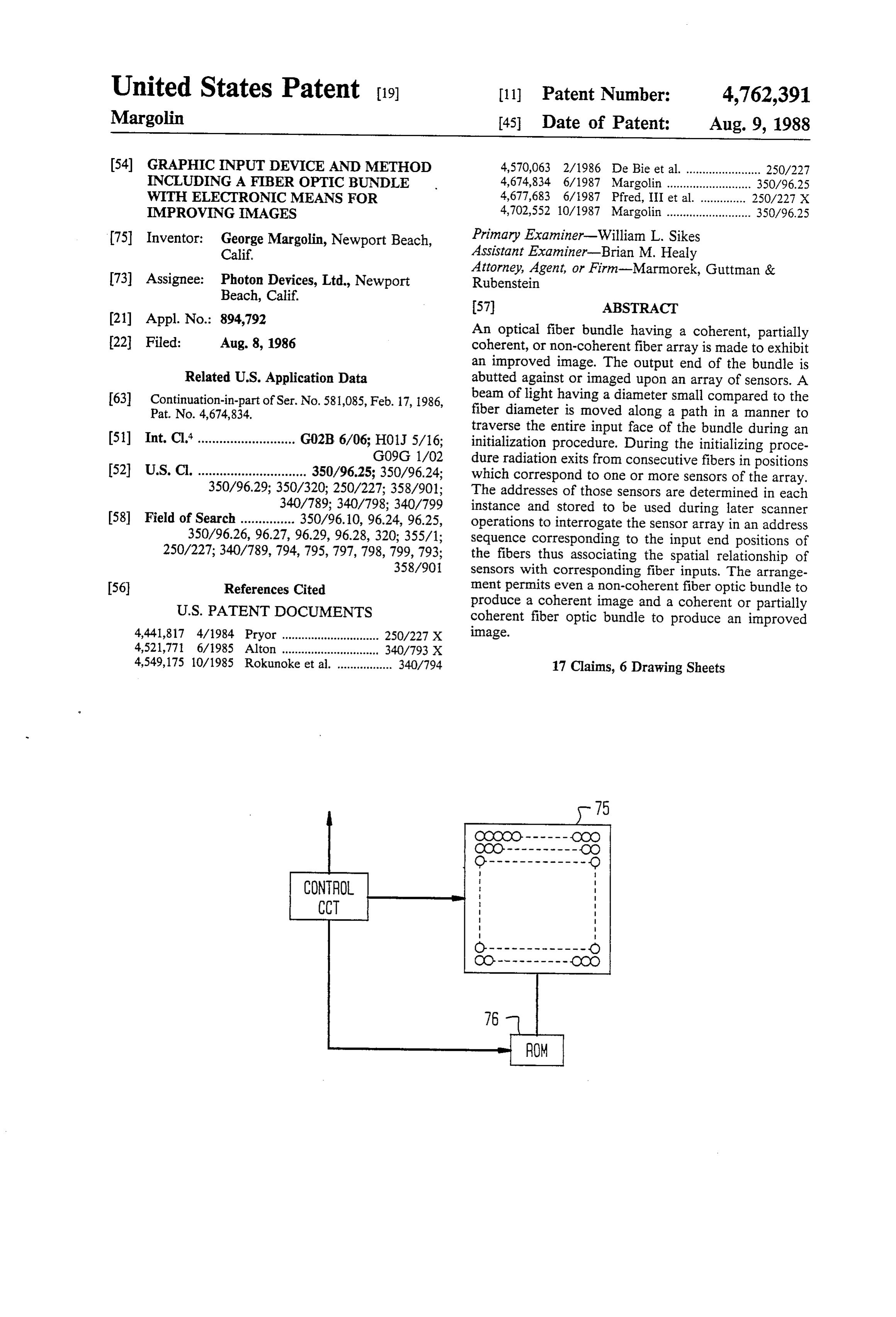
CONTROL
CCT
Page 2
Drawing sheet — no readable text.
Page 3
Drawing sheet — no readable text.
Page 4
Drawing sheet — no readable text.
Page 5
Drawing sheet — no readable text.
Page 6
Drawing sheet — no readable text.
Page 7
GRAPHIC
BACKGROUND
CLOSE BOB
DATA FILE
EXIT
SNAP PICTURE
STEP INITIALIZER
BEAM
STRIP BACKGROUND
FIND BLOB
BOB FOUND?
YES
SAVE BLOBIN TEMP SAVE BLOBIN
REGION "BLOB DATA FILE" TEMP REGISTER
SAVE NEW BLOB
IN TEMP REGISTER
Page 8
GRAPHIC INPUT DEVICE AND METHOD
able only as long as the fiber diameter equals the size and location of the sensor to which it is attached. But if
NCLUDING A FIBER OPTIC BUNDLE WITH a mismatch occurs in size or location, the group of ELECTRONIC MEANS FOR IMPROVINGIMAGES pixels transmitted by the fiber bundle can cause the
CROSS REFERENCE TO COPENDING
image to be degraded significantly. Not only is impor
APPLICATION tant information lost, but, in addition, many degrading artifacts may occur, such as aliasing and moire patterns.
The present application is a continuation-in-part of copending application Ser. No. 581,085, filed Feb. 17, 10 BRIEF DESCRIPTION OF THE INVENTION 1986, now U.S. Pat. No. 4,674,834, and assigned to the The initializing arrangement disclosed in the above assignee of the present application. This prior patent identified copending application is used herein in con application is incorporated herein by reference. junction with a coherent fiber optic array permissibly FIELD OF THE INVENTION with fibers mismatched in size and/or location imaged onto or abutting an electronic sensor array. The initial
This invention relates to a graphic input device em 15 izing arrangement is employed exactly as disclosed in ploying a coherent fiber optic bundle operative to apply that copending application to generate a subset of ad a group of pixels to an electronic sensor array. dresses of sensors of the sensor array interrogated dur BACKGROUND OF THE INVENTION ing each scan period. Thus, the input ends of fibers of a coherent fiber bundle are associated with the addresses
It is well known to employ a coherent fiber optic 20 bundle to apply a group of pixels to a sensor array. Such of sensors interrogated so that the image scanned can be reconstructed in the sequence determined during the a system employs a fiber for each sensor and requires initialization procedure.
the attachment (or imaging) of a fiber onto the associ in spite of any mismatch.Superior images are achieved ated sensor in order to achieve a defect-free image. For useful in industrial and medical scopeis applications The invention particularly large numbers of fibers, particularly when the fibers 25 have very small diameters, the attachment of the fibers wherecule high resolution requires large numbers of minus fibers even when the sensors of the sensor array are to the associated sensors is tedious, difficult, and expen spaced apart relatively farther than are the fibers and sive to achieve.
The above-mentioned copending application dis the input face of the fiber bundle is imaged onto the closes a technique not only for achieving a coherent 30 vsensor array.
Initializing
apparatus for moving a relatively small image from a fiber optic bundle, but also by doing so beam of light incrementally along a path in an input face with a non-coherent bundle and by doing it in a manner which eliminates the need for associating each fiber of a fiber optic bundle to intersect the fiber ends one by with a corresponding sensor or for predetermining its one and the determination of a corresponding sensor of position ahead of time. Instead, the output end of the 35 a sensor away coupled to the output face of the bundle fiber optic bundle is associated with a sensor array with is considered to represent a considerable departure from out regard to the spatial relationship of the fibers and prior art thinking. The use of such apparatus particu the sensors of the array. But the fiber diameter is chosen larly for initializing already coherent fiber optic bundles to be large compared to the size of a sensor or the fiber is also thought to represent a significant departure from exit end is imaged onto the sensor array in a manner to prior art thinking.
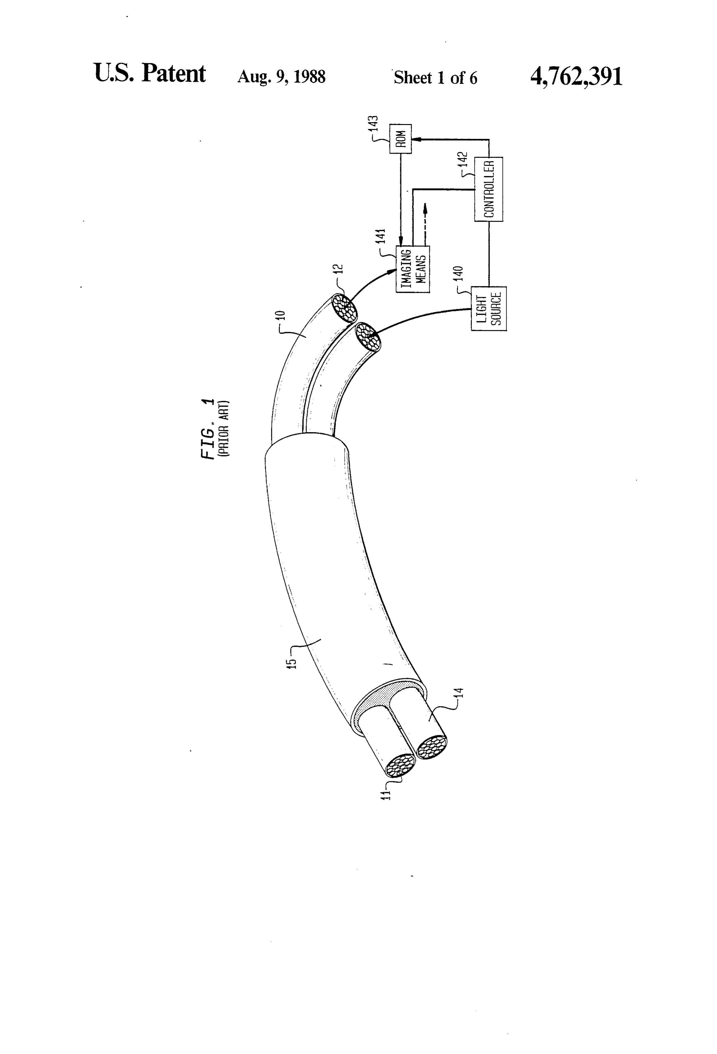
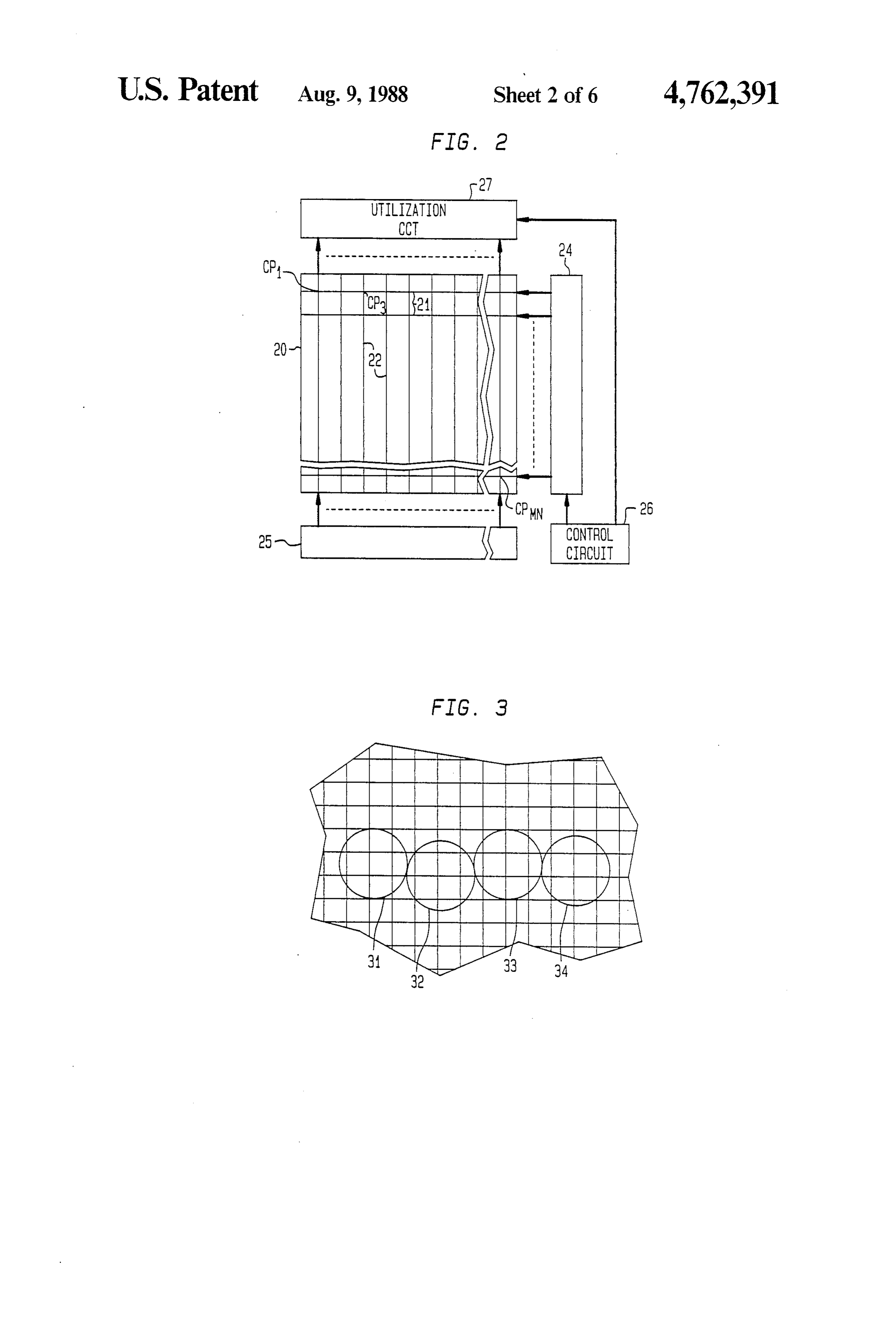
correspond to a plurality of sensors. BRIEF DESCRIPTION OF THE DRAWINGS An initializing arrangement is used to determine which sensors correspond to a particular fiber of the FIG. 1 is a perspective view, partially cut away, of a bundle wherever that fiber may be located in the bun scope for use in industrial or medical applications; dle. The initializing arrangement is adapted to move a 45 FIG. 2 is a schematic top view of a random access beam of radiation incrementally along a path in the memory adapted for use as a sensor array with the input face of the array in a manner to intersect the fibers scope of FIG. 1 in accordance with the principle of this in an ordered sequence. The beam is incremented along invention;
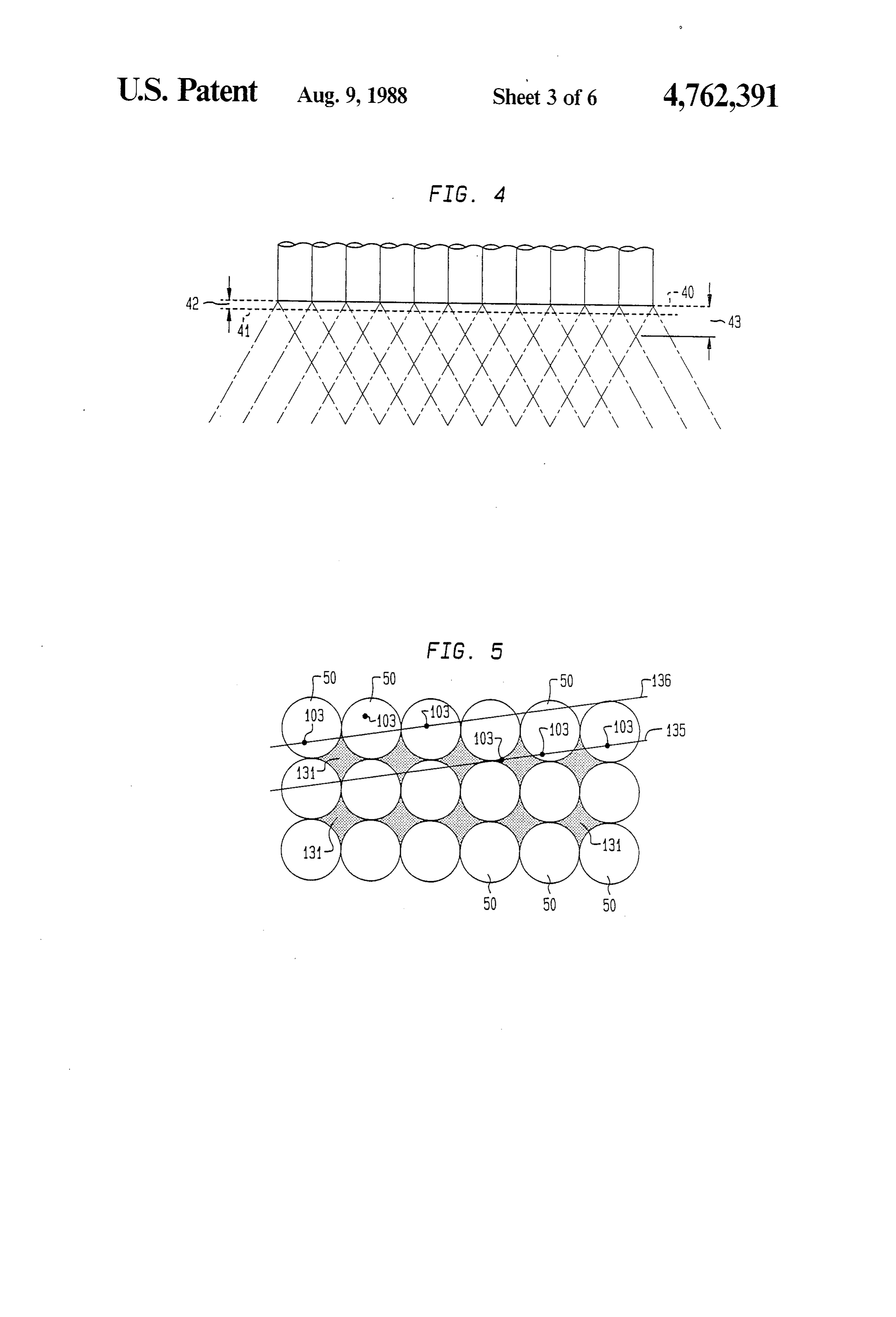
the path such as to intersect the fiber ends and the sen FIG. 3 is a schematic top view of the memory of sor array is interrogated, in each instance, to determine 50 FIG. 2 with the ends of a few of the fibers of FIG. 1 which sensors are illuminated each time the beam is superimposed thereon;
moved. Because the beam diameter is relatively small, FIG. 4 is a schematic side view of the arrangement of there is no need to move the beam accurately to the FIG. 3 showing the relationship between the fiber out precise positions of consecutive fibers in the input face. put and the sensors of the array of FIG. 2; In this manner, a non-coherent fiber optic bundle is 55 FIG. 5 is a schematic view of a fragment of a fiber made to provide a coherent image electronically in a optic bundle of FIG. 1 showing an end view of a plural simple and inexpensive manner. ity of fibers with sensor positions super-imposed The present invention is based on the recognition that thereon;
the initializing arrangement can be made to serve a FIG. 6 is a schematic block diagram of an initializing benefit for coherent fiber optic bundles as well as non arrangement for a one-dimensional fiber optic array; coherent fiber optic bundles when used as an input to a FIG. 7 is a schematic top view of a sensor array random access, electronically addressed readout, imple showing the positions of a cooperating coherent fiber mented with a CCD, CID, optic RAM chip, or Vidicon optic bundle superimposed thereon;
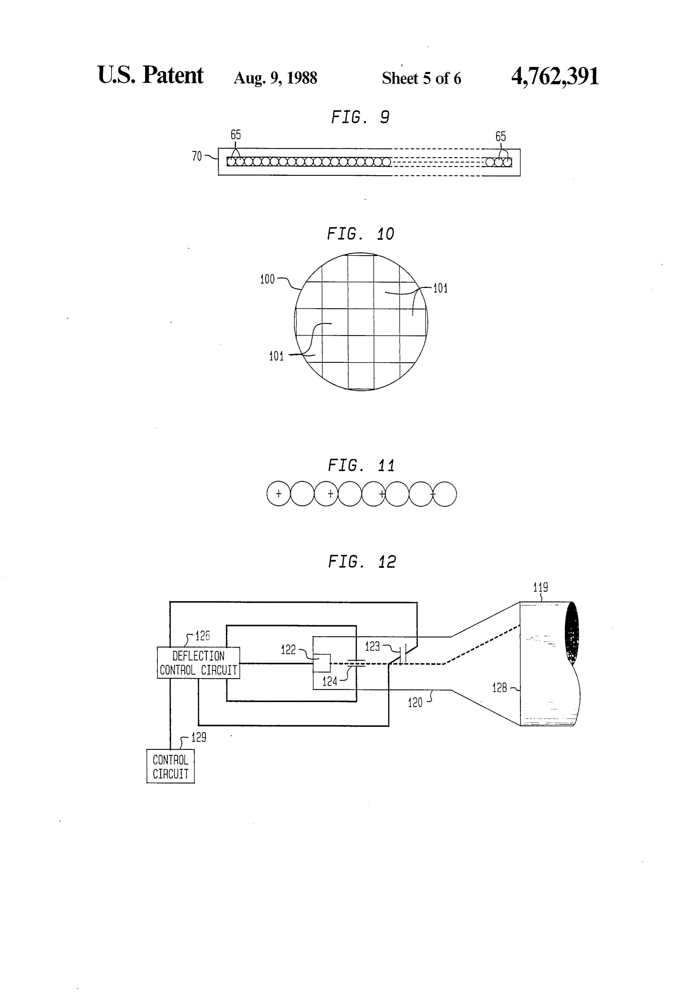
technology. The problems that arise with respect to FIG. 8 is a perspective view of a portion of a docu coherent optical fiber bundles have to do primarily with 65 ment scanner cooperative with the sensor array of FIG. a mismatch between the diameter or shape of a fiber in 7 in accordance with the principles of this invention; the bundle and the size, shape, and/or location of the FIG. 9 is an end view of a linear end of a fiber array sensors of the array. The transmitted image is accept of the scanner of FIG. 8;
Page 9
FIG. 10 is an enlarged schematic view of one fiber of abut the sensor array. A typical case is illustrated by the fiber array of FIG. 9 superimposed on a plurality of superimposing illustrative fibers of a fragment of bundle sensors of a cooperating sensor array; 10 onto the array as represented by circles (fibers) 31, FIG. 11 is an enlarged schematic end view of a por 32, 33, and 34 in FIG. 3. This case illustrates a simple tion of a fiber optic bundle with selected associated misalignment between a line of fibers in the bundle and sensors of a cooperating sensor array; and a row of sensors where the fiber size is taken as about FIG. 12 is a schematic block diagram of an initializing two and one halftimes the size of a sensor diagonal. It arrangement for a two-dimensional fiber optic array can be seen that fiber 31 illuminates twelve sensors fully useful with the scope of FIG. 1. or partially, fiber 32 illuminates fourteen, fiber 33 illumi FIG. 13 is a flow diagram which shows how the 10 nates twelve, fiber 34 illuminates eleven sensors. Such a scanner is initialized. typical correspondence allows only about two unam DETALED DESCRIPTION biguous sensors to be reliably determined for each fiber because of spill over of the light from neighboring fi
FIG. 1 shows an optical fiberbundle 10 which has an bers. This result is understood when it is realized that input end 11 and an output end 12. The optical bundle is 15 even a coherent bundle of fibers would not necessarily intended for use in a medical or industrial scope for have fibers neatly aligned in rows, nor would the fibers examining inaccessible areas. The optical bundle is used be evenly spaced, nor would the cut and polished out in conjunction with a second optical bundle 14 (nor put end of the bundlebe optically flat or seat flat against mally used for illumination), the two optical bundles the sensor array. With respect to this last-mentioned being encased in a flexible tube 15 which may include problem, the fibers may have a numerical aperture of, apparatus for manipulating the input end in a manner to say 0.5. Consequently, if the bundle is not optically flat follow a tortuous path, the entirety representing a medi and against the array, spill-over occurs between the cal or industrial scope. Such scopes are commercially signals of neighboring fibers creating unwanted artifacts available. in an image gathered by the sensor array. The term Commercial scopes typically are adapted at the out 25 “Spill-over” refers to the condition where light from put end for viewing through an eyepiece. When they neighboring fibers illuminate common sensors. are adapted for capturing an image electronically, a FIG. 4 shows the spill-over effects. The exit end of poor image is obtained in the absence of costly and time the fiber bundle is represented as line 40, the fibers consuming image enhancement. extending upwardly from line 40 as viewed. The sensors The reason for the poor image has to do with the 30 are positioned in a plane represented by broken line 41. physical characteristics of the sensor array adapted for It is clear that the separation 42 between the end of the capturing the image, the "coherent' character of the fiber bundle and the sensor plane is advantageously less fiber array and the mismatch between fiber size and than the distance 43, which equals the image spread of spacing and sensor size and spacing. The poor image the fibers, in order to avoid having light from more than also occurs because of different sensitivities of the sen 35 one fiber illuminate common sensors. The illumination sors and different transmission characteristics of the of common sensors could occur even if the fiber bundle fibers. In truth, a prior art coherent fiber bundle is sel exit face is optically flat and parallel to the sensor plane. dom, if ever, really coherent, particularly for electronic If the plane of the fiber end is not parallel to the sensor image taking, unless a very costly dine to one correspon array, spill-over could occur only at some portions of dence between each fiber and its associated sensor is the sensor array.
fixed physically. FIG. 5 shows a regular pattern of fibers 50. Such a FIG. 2 shows a schematic illustration of a sensor pattern superimposed over the regular pattern of the array 20 useful in accordance with the principles of the sensor array (see FIG. 3) leads to Moire patterns and to present invention. The sensor array is shown organized aliasing. Such effects lead to artifacts in the electroni as a standard random access memory, but could be a 45 cally generated image in a well understood manner. charge-coupled device (CCD) organized as a random Clearly, anything less than matching fiber diameter access device, a similarly organized charge-injected with sensor size and the attachment of such a fiber in a device (CID), or any other suitable random access sen coherent bundle to a corresponding sensor of an array sor array. The sensor array includes x and y conductors, can result in image degradation and artifacts which are 21 and 22 respectively, which define cross points where 50 eliminated only at great cost. Arrangements which meet they intersect. The cross points are designated CP1, such exacting requirements are used commercially in, CP2, . . . CPMN, for an M row by N column array and for example, engineering drawing scanners where the are taken to represent individual sensors. The row con input end of the bundle is held in a linear array and the ductors are connected to an x-address generator 24 and output end is precisely attached to the sensor array as the column conductors are connected to a y-address 55 described.
generator 25. The address generators are controlled by In accordance with the principles of the present in a control circuit 26. In operation, using common sen vention coherent fiber optic bundles can provide an sors, all the sensors of the array may be thought of as electronically digitized image when abutted or imaged pre-charged (or discharged) during one cycle of opera onto a sensor array without any of the above-mentioned tion and the amount of incident radiation determines the 60 problems. The fiber bundle is merely attached to the amount of charge remaining (or acquired) when a read surface of the sensor array, or imaged onto it, and then cycle next occurs. The readout signals are applied to a initialized to determine the sensors illuminated when a utilization circuit 27 in a well understood manner. beam of light is directed into consecutive fibers of the FIG. 3 is a schematic representation of a portion of input end of the bundle. The initializing procedure se array 20. The sensors are shown in squares in FIG. 3, 65 lects a subset of sensors of like sensitivity first and then the sensor arrays typically being constructed so that the selects one sensor from that subset for each fiber illumi sensors occupy virtually the entire area of the array. nated. The initializing procedure need only determine Consider what happens when the fibers of bundle 10 what sensor in the sensor plane is illuminated and, in
Page 10
effect, normalizes the system for any fiber-sensor mis mum in the number of illuminated sensors occurs in one matches of any kind thus eliminating any artifacts and area of the array, that maximum or "blob” of sensor aliasing effects. addresses is stored and one sensor from the blob is se FIG. 6 shows, schematically, the organization of an lected as representing an output position of a fiber. initializing arrangement in accordance with the princi Thus, when fiber 100 is illuminated during an initial ples of this invention. The arrangement is adapted for izing operation one of the sensors (101) represents its initializing of a fiber optic bundle having a linear input output position.
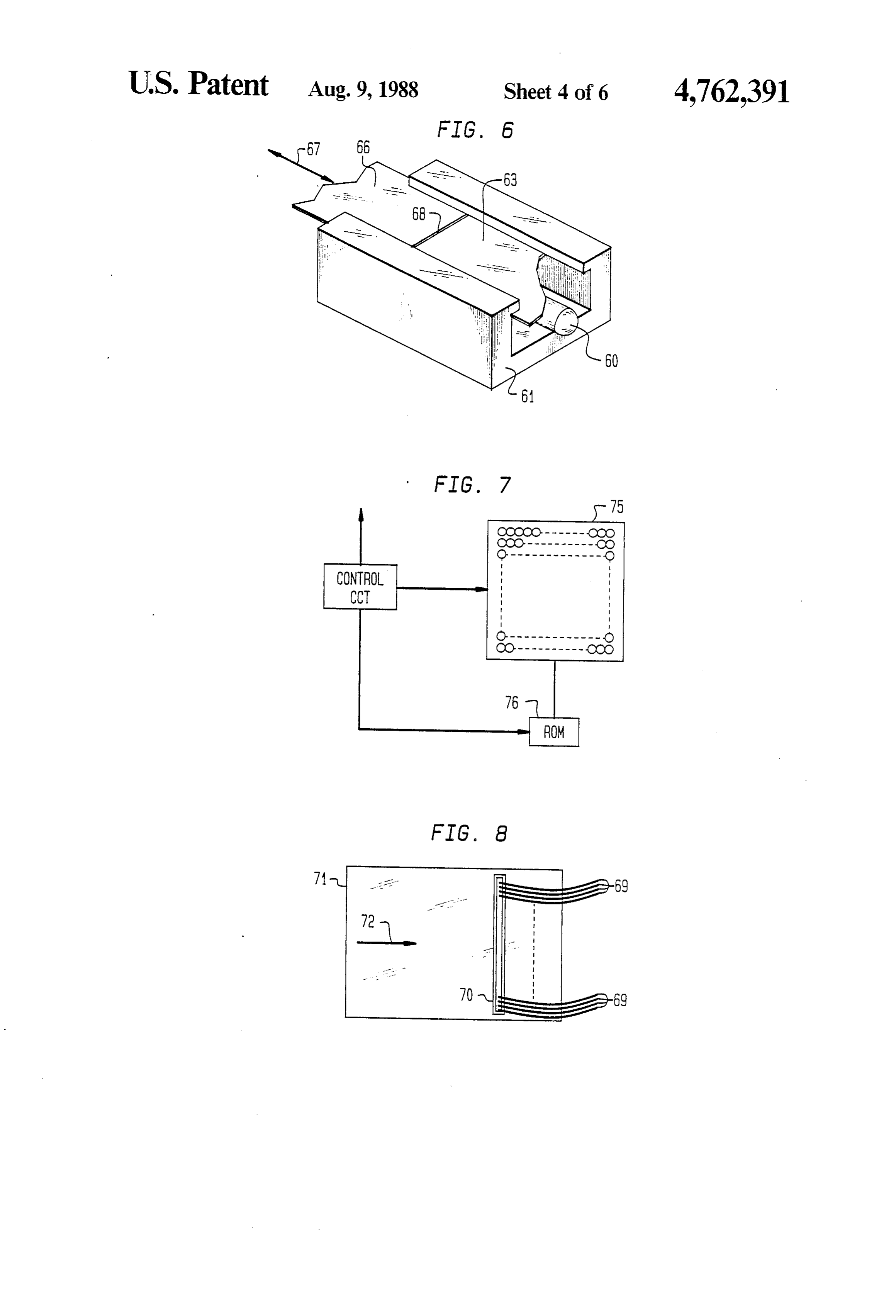
geometry useful for scanning a document at line-at-a- The initializing arrangement is conveniently prepro time as disclosed in the above-mentioned copending grammed to illuminate the sensors of memory 75 (of application. 10 FIG. 7) in sequence and to select all the sensors that The initializing arrangement of FIG. 6 includes an optic RAM and a read-only memory (ROM) to sense have (or sensitivities which fall within a prescribed window windows). This procedure has been found to pro and store the addresses of sensors activated when a light beam is moved incrementally along the linear end of the vide one or more sensors (a subset of the plurality of sensors illuminated) of like sensitivity for each fiber.
fiber optic bundle. FIG.7 shows the optic RAM and the 15 The procedure is accomplished simply by illuminating ROM organization. FIG. 8 shows the orientation of the the fibers linear end of a fiber optic bundle and FIG. 9 shows an recordingfor different prescribed periods of time and by the addresses of the illuminated sensors each end-on view of the fibers of FIG. 8. The initialization procedure is carried out by moving a relatively small adapted time. The initializing procedure thereafter can be diameter beam or slit of light incrementally along a path 20 twelve orto select one sensor of like sensitivity out of the so sensors illuminated for each fiber. The in the input face past each of the fiber ends of FIG. 9, in position of that sensor may vary with respect to the sequence, the beam being small compared to the fiber fiber end as represented by the black dots 103 of FIG. 5. SZC.
Still, a clearer artifact-free image is produced by the
The arrangement of FIG. 6 includes a light source 60 resulting enclosed by a housing 61. A side 63 of housing 60 is 25 arrangement. Also of importance, since only placed adjacent to ends 65 of FIG. 9. Side 63 includes one (or a few) of the many sensors illuminated by each an opaque film or tape 66 which is moved along axis 67 iffiber is interrogated, the speed at which the whole array interrogated during each scan period is vastly in represented by the double headed arrow so designated creased.
in FIG. 6. The tape includes a slit 68 having a width
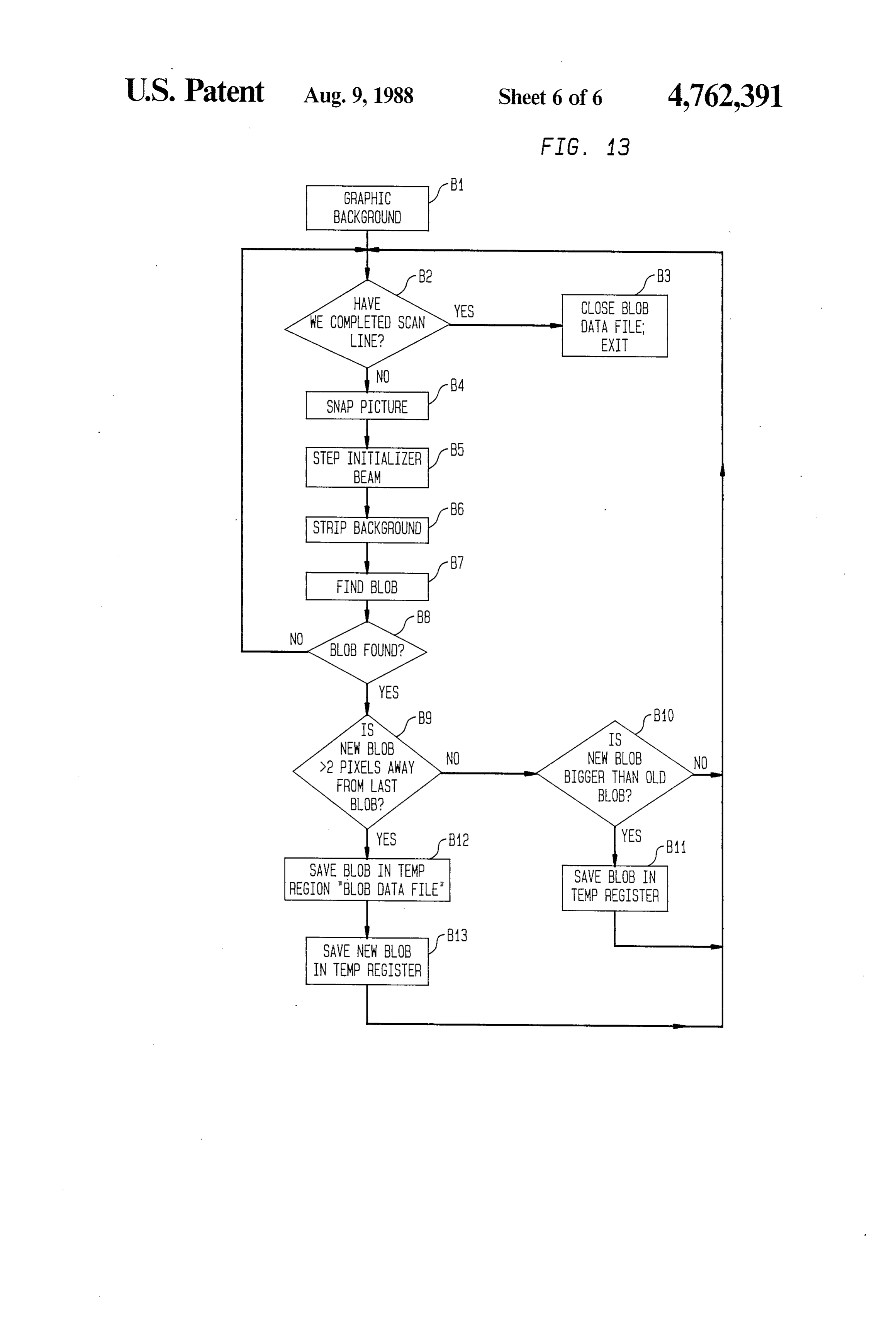
A Personal Computer is useful for controlling the small compared to the diameter of a fiber and thus, 30 initializing when moved incrementally will at some positions illu procedure. Software is provided for deter minate the fibers of the linear array, one at a time. Soft mining the occurrence of a maximum number of illumi ware is adapted to store addresses of illuminated sensors nated sensors, a "blob', by comparing the number of when a maximum number of sensors in one area of the illuminated sensors to the number illuminated for the array is illuminated. 35 preceding beam position and for ensuring that the cen FIG. 8 represents the fibers as lines 69 extending from ter of the blob is at least two sensors away from the a ferrule 70. The ferrule is adapted to hold the linear end previous center. A flow diagram for the software is as in an energy coupled relationship to a document to be follows:
copied. The document is represented by rectangle 71. In The procedure starts with the gathering of the back use, the document is moved in the direction of arrow 72 ground noise from the sensor when it is not illuminated by means of a conventional paper moving apparatus as as indicated in the top of box, B1, of the flow diagram. disclosed in my above-mentioned copending applica This step permits us to subtract, for example, bad sen tion. It is the fiber ends held by ferrule 70 which are sors which always indicate an illuminated condition. positioned in the path along which light is moved and The next box, B2, is directed at determining if an thus are illuminated, one by one, during the initializing 45 entire scan line (or operation) is completed. If yes, the procedure. The remote or exit end of the fiber bundle is blob data file is closed and we exit the program as indi gathered in a coherent or a non-coherent fashion, and cated in box B3. If no, a next scan period occurs-the abutted against (optical) RAM 75. equivalent of snapping the next picture as indicated in FIG. 7 shows a sensor array 75 with a coherent ar box B4.
rangement of fibers superimposed on it. That is to say, 50 Box B5 indicates that the initialized beam is stepped the physical positions of the fibers at the linear end and and box B6 indicates that the background is stripped the physical positions of the fibers at the remote end away. These steps provide the addresses of sensors abutting array 75 are homologous. But the positions in illuminated by the beam. Boxes B7 and B8 represents the linear end are not predetermined nor are those posi the procedure for finding a maximum number (or blob) tions prerecorded in the read only memory (ROM) 76 55 of illuminated sensors in one area of the array. If a blob of FIG. 7. Instead, the initializing arrangement is opera is not found we return to block B2. If a blob is found, we tive to increment the slit 68 of FIG. 6 and to interrogate determine its distance from the previous blob as indi sensor array 75, in each instance, to determine which cated in box B9. If the blob is not more than two pixels sensors are illuminated. The addresses of those sensors or sensors away from the preceding blob, we determine are stored in ROM 76 or in a look-up table on disk for 60 if the new blob is bigger as indicated in box B10. If it is later use, for example, for "burning” an EPROM (elec not, we return to box B2. If it is, we save the blob in a trically programmable read only memory). In this con temporary register as indicated in box B11 and then we nection, a typical fiber may overlay say twelve or six return to Box B2.
teen sensors. This relationship is represented in FIG. 10 If the new blob was more than two pixels away from for a fiber 100, the sensors being represented by squares 65 the previous one, we have a new blob. We save the new 101. The initializing arrangement, in this case, is blob in a temporary register and stove the old blob in a adapted to record all the addresses of illuminated sen blob data file as indicated in box B13 and return to box sors each time the beam is incremented. When a maxi B2.
Page 11
FIG. 11 illustrates the case where the fiber diameter increments smaller than a fiber diameter and the beam is small compared to the spacing between sensors, rep size is made small compared to a fiber diameter. Conse resenting the sensors as plus signs to emphasize the quently, at least one or more addresses can be deter separation between sensors. It may be convenient, in mined from a sufficient number of beam positions to this case, to employ a lens to image the output end of the provide virtually any required resolution. fiber bundle onto the sensor array to achieve the rela Once again, because the initializing procedure selects tionship of FIG. 10. But a lens is an expense and results one beam position for one (or more sensors), it thus can in a considerable loss of light. This may be tolerable, but select one fiber for each such position also. Conse must be considered in the design of the system. quently, the resulting system avoids the possibility of If it is undesirable to use a lens, the initializing ar O two separate patterns (fibers and sensors) which could rangement is operative in any case to select only those lead to Moire patterns or to aliasing when signals are fibers which do in fact illuminate a sensor. The remain applied during operation. Moreover, mismatch between ing fibers (i.e. broken or misplaced or superfluous fi fiber size and/or location and sensor size and/or loca bers) are not used. As long as the selected fibers provide tion, or the presence of voids, such as voids 131 of FIG. an acceptable resolution, the fiber bundle is useful and 15 5, cause only negligible problems if any. Further, the free of artifacts. misalignment of fiber rows and sensor rows which The foregoing discussion was directed an initializing could lead to artifacts in prior art systems can be cor a fiber bundle which has a linear organization at the rected during the initializing operation. For example, input end. For industrial or medical scope uses, both such a misalignment could lead to a step in a straight ends of the fiber bundle are two dimensional. That is to 20 line in an image being digitized by a scope, where no say, both the input and output ends of the fiber bundle step actually exists. The step would occur because at are, for example, circular as shown in FIG. 1. some point along the line, the image would appear to FIG. 12 is a schematic block diagram of an arrange correspond to the sensors of a next adjacent row. This ment adapted to initialize a two dimensional array of is illustrated in FIG. 5 by straight lines 135 and 136. fiber ends as shown in FIG. 1 or FIG. 5. It is, of course, 25 Consider rows of sensors aligned with lines 135 and 136. important to illuminate a selected (single) fiber-at-a-time An image of a straight line produced by fibers 50 of the during the initialization operation. There may be over top row of fibers as received will be recorded as a four thousand fibers in a linear array as shown in FIG. stepped line, the portion of the image corresponding to 9. Moreover, each of those fibers has a diameter of two the three fibers of the top row to the left as viewed mils (50 microns) or less. In a high resolution scope, 30 corresponding to sensors along line 136, the three to the there may be ten thousand fibers or more and each fiber right corresponding to sensors of line 135. The resulting may have a diameter of fifteen microns or less. The image artifact is eliminated during the initialization initializing procedure is not trivial. But it can be accom operation herein.
plished by a procedure similar to that of the organiza In fact, because the sensor array is a sensor and the tion of the printer arrangement disclosed in the above 35 fiber bundle transmits points of light, the output of the mentioned copending application. FIG. 12 shows such sensor array can be viewed via a monitor during manu an arrangement. Simply put, the input end of a bundle facture so that the process of attaching the fibers to the offibers 119 organized in some two-dimensional geome sensor array can itself be used to avoid misalignment of try, typically circular, is abutted against, or imaged the type described, a procedure which suggests its use from the face of a cathode ray tube (CRT). The CRT is 40 as a positioning device for industrial use. When the fiber capable of directing an electron beam to any one of bundle comprises a number of finger-like bundles, the hundreds of thousands of points on the face of the CRT, arrangement can be used in a mechanical manipulator many times the number of fibers used in commercially such as a robotic hand, to position objects and to ob available fiber scopes. The CRT is designated 120 in serve the movement in detail. All the fiber bundles of a FIG. 12 and includes a cathode 122 for generating elec 45 group of manipulator "fingers' can be attached to a trons. The x and y deflection plates common to such single sensor array in the "palm of the hand', providing tubes are designated 123 and 124 respectively. The a simple "sighted tool”.
deflection plates are operative in response to voltages Thus, it should be clear that even a coherent fiber applied by deflection control circuit 126. Normal raster optic bundle has problems which cannot be corrected scan operation for such a tube proceeds from side to SO easily in the absence of an initialization procedure dis side on faceplate 128 and then increments to the next closed herein. Of course, the procedure is usable with a line for repeating the operation until the entire faceplate non-coherent fiber optic bundle as disclosed in the is scanned. The presence of a beam of electrons in each above-mentioned copending application also. position causes phosphors on the inside of the faceplate A system or combination of elements herein includes to emit light. Alternatively, a CRT of different con 55 a coherent (or a partially coherent or non-coherent) struction permits the electron beam to be vectored to fiber optic bundle, a cooperating sensor array and positions in any specified sequence. Operation is under means for interrogating the subset of addresses in the control of control circuit 129. Light exiting to a fiber in sensor array generated during the initializing proce a position corresponding to excited phosphors impinges dure. The means for interrogating for example, conve on sensors as was the case with the initialization of a 60 niently comprises a read only memory 143 programmed linear array. accordingly to interrogate only the selected sensors of The initializing operation merely relates the position the array, in the address sequence obtained during ini of the electron beam to the address of a sensor or sen tialization, each time a scan period occurs. A scan per sors illuminated for each position of the beam. It is not iod occurs when, for example, light from light source necessary to direct the beam at a specific fiber end to 65 140 of FIG. 1 is incident on an object and the sensor accomplish this task. It is only necessary to increment array 141 is interrogated under the control of controller the beam along its path and to record the addresses 142. It is convenient to strobe light source 140 and to illuminated in each position. The beam is moved in activate imaging means 141, when desired, in synchro
Page 12
nism with the strobe. The pixels sensed during each when said object is illuminated, said unique subset of scan period are stored in a memory for processing under sensors being determined during an initialization proce the control of controller 142 as disclosed in my above dure during which a beam of light is moved incremen mentioned copending application. tally along a path in said input face in a manner to inter What is claimed is: sect the input ends of the fibers in said bundle in succes 1. A combination of elements for controllably activat sion and the addresses of the sensors illuminated in each ing a unique subset of sensors in a sensor array during a instance are recorded for determining said subset, said scan period when an object is illuminated, said combina beam of light having a diameter small compared to a tion comprising a sensor array and a coherent fiber fiber diameter.
optic bundle adapted to direct light representative of 10 11. A method for determining the relationship be said object onto said array, said combination including tween the fibers of a fiber optic bundle having an input permanent memory means for storing the addresses of and an output face and the sensors of a sensor array onto said unique subset of sensors determined during an ini which the bundle is operative to direct an array of pix tialization procedure, and means for interrogating said els, said method comprising the steps of positioning said unique subset of sensors of said array in a manner to 15 bundle such that the pixels exiting said output face of provide the correspondence between each fiber and at said bundle impinge upon the surface of said array, least one associated sensor each time a scan period oc moving a beam of radiation of relatively small diameter CS incrementally along a path in said input face which 2. A combination in accordance with claim 1 wherein intersects said fibers in an ordered sequence, each of said subset comprises a single sensor for each of said 20 said fibers having a relatively large diameter, interro fibers. gating said array in a manner to determine which sen 3. A combination in accordance with claim 1 wherein sors of said array are illuminated each time said beam is a pixel formed from each of said fibers covers an area of moved along said path, and storing the addresses of the said sensor array which includes a plurality of sensors. sensors illuminated each time a maximum in the number 4. A combination in accordance with claim 3 wherein 25 of illuminated sensors in one area of said array occurs. the output end of said fiber bundle is attached to said 12. A method in accordance with claim 11 also in sensor array. cluding the steps of selecting the addresses of a single 5. A combination in accordance with claim 3 also sensor in each of said maximum number of sensors for including a lens, said lens being adapted to focus the forming a subject of addresses.
pixels from the output end of said fiber optic bundle 30 13. A method in accordance with claim 11 wherein onto said sensor array. said fiber optic bundle is at least partially coherent. 6. A combination in accordance with claim 3 wherein 14. A method in accordance with claim 12 also in each of said fibers has a diameter large compared to a cluding the step of programming a ROM to store the sensor of said sensor array, and said sensors are closely addresses of said unique subset of sensors. spaced such that each of said fibers corresponds to a 35 15. A method in accordance with claim 14 also in plurality of said sensors. cluding the step of selecting the sensors of said array 7. A combination in accordance with claim 6 also which have sensitivities which fall within a prescribed including means for selecting one or more of said plural range of sensitivities.
ity of sensors which corresponds to each of said fibers. 16. Apparatus for initializing a fiber optic bundle, said 8. A combination in accordance with claim 7 also 40 apparatus including means of moving a relatively small including means for deselecting the remaining ones of beam of light incrementally along a path which inter said plurality of sensors which corresponds to each of sects the input ends of the fibers of said bundle, an elec said fibers. tronic sensor array energy coupled to the output face of 9. A combination in accordance with claim 5 wherein said bundle and including a plurality of sensors for each the diameter of each of said fibers is less than about the 45 of said fibers, memory means for storing the addresses size of one of said sensors, and, neighboring ones of said of said sensors each time said beam is moved, means for fibers are spaced apart distances small compared to the determining the occurrence of a maximum number of spacing between neighboring ones of said sensors. illuminated sensors in one area of said array, means for 10. An electronic imaging arrangement, comprising selecting at least a single address from each of said an at least partially coherent optical fiberbundle having 50 maximum number and means for forming a subset of input and output faces, said input end being adapted to addresses including each of said single addresses. accept light from an object, said output end being 17. Apparatus in accordance with claim 16 also in adapted to apply pixels representative of said object to cluding means for selecting sensors of said array which a sensor array, said pixels formed by said fiber bundle, have sensitivities which fall within a prescribed range of means for illuminating said object and means for inter 55 sensitivities.
rogating a unique subset of sensors in said sensor array ck ck : s s
Provenance
- Collection
- Cited prior art
- Original PDF
- patentimages.storage.googleapis.com →
- Filed
- 1986-08-08
- Pages
- 12
- Method
- pdftotext (the PDF's own text layer) + pdftoppm 300dpi page scans
- Source
- Google Patents bibliographic record
- Granted
- 1988-08-09
- Inventors
- George Margolin; PHOTON DEVICES Ltd
- Transcribed from
- patentimages.storage.googleapis.com →