patent · US4738510
Fiber optic display device and method for producing images for same
19 April 1988
Page 1 — bibliographic record
United States Patent (19) (11) Patent Number 4,738,510 Sanso (45) Date of Patent Apr. 19, 1988 (54) FBER OPTCDSPLAY DEVICE AND 4,057,338 11/1977 Yevick ... 330/96.24 METHOD FOR PRODUCING IMAGES FOR 4,185,888 1/1980 Quelle, Jr. ...... 350/96.25 SAME 4,223,343 9/1980 Belmares-Sarabia et al. ........ 358/S4 4,290,688 9/1981 Call ..........................is......... 355/1 (76 Inventor: William L. Sanson, 317 St. Pauls 4,352,550 10/1982 Uchida .......... ... 355/3 R Ave., Jersey City, N.J. 07306 4,570,063. 2/1986 De Bie et al. .................... 250/227 4,63,210 9/1986 Pollard ......................... 350/96.2S X
22 Filed: Mar. 28, 1985 FOREIGN PATENT DOCUMENTS (51) late C.'......................... G02B6/06; F2IV 7/04; 56-83705.7/1981 Japan ................................ 350/96.24 G09F 13/00; G03B 27/00 Prinary Examiner-William L. Sikes (52) U.S. C. ............................. 350/96.25; 350/96.24; Assistant Examiner-Brian M. Healy 350/96.10; 350/320; 350/96.27; 362/32; 57 ABSTRACT
(58 Field of Search ................ 355/1; 362/32;40/547, A fibre optic display device utilizing optical fiber ele 40/427,438; 250/227; 350/96.10, 96.24, 96.25, ments whose light emitting ends are arranged in a dis 96.27, 96.29, 320 play screen matrix and whose light-receiving ends are (56) References Cited reorganized and gathered in a bundle in a non-linear image-receiving matrix. A defined image previously
2,982,175 5/1961 Eisler ................................ 350/96.24 display screen by being specifically decoded when the 3,202,045 8/1965 Arsenault et al. ............... 350/96.24 transparency is in registration with the light-receiving 3,489,482 l/1970 Brill ................................. 350/96.0 ends of the bundle in the image receiving matrix. Mov 3,560,085 2/1971 Silverberg. ing the encoded image into and out of registration 3,781,109 12/1973 Mayer, Jr. et al. .................. 355/52 causes the transparency to produce special effects on 3,815,986 6/1974 Darbee .................................... 355/ 3,836,911 9/1974 Gibson et al. . ... 350/96.24 the display screen.
3,909,109 9/1975 Aurenz .......... 350/96.24 3,914,877 10/1975 Hines .................................... 380/54 14 Claims, 3 Drawing Sheets
Page 2
Drawing sheet — no readable text.
Page 3
Drawing sheet — no readable text.
Page 4
Drawing sheet — no readable text.
Page 5
ricate by known techniques due to the necessity of con
FIBER OPTIC DISPLAY DEVICE AND METHOD necting each end of an image receiving fiber to the FOR PRODUCING MAGES FOR SAME corresponding end of an image-projecting fiber in the same spacial relationship which heretofore has been
This invention relates to a fiber optic display device S accomplished manually, for projecting through a display screen programmed Moreover, no unusual display "special effects" are defined and undefined images, and which is also capable accomplished in this manner, such as dramatic varia of producing special visual effects which herebefore tions in color, fade-in and fade-out, wipe-in and wipe could be achieved only by electronic and/or complex out, exploded images and imploded images, variations photographic techniques. O in brilliance, and the like, all of which can be accom BACKGROUND OF THE INVENTION plished by using non-coherent or reorganized fibers in It has been recognized in the field of optical displays accordance with the present invention. Accordingly, that a coherent bundle to matrix arrangement of optical the present invention it is a principal object accomplished by fibers produces an ideal medium for pictorial display. to provide a relatively low cost optical fiber display
By "coherent bundle to matrix arrangement" is meant images for same which overcomesdevice and method for producing that each optical fiber exposed to a source of light and ciences of the prior art, and at the same the aforesaid diffi an image for projection through a "projection matrix" it intermittent defined image projection and time facilitates. is connected to a display screen at a point correspond fects" in the same device. "special ef. ing to the respective fiber exposed to the image and 20 light source, thereby to duplicate the image on the dis SUMMARY OF THE INVENTION play screen matrix face. Generally, the fiber points in the display screen matrix face are more widely spaced ityThe device of this invention is composed of a plural of optical fiber elements. Their light emitting ends from one another than are the corresponding fiber are placed in a predetermined pattern, ideally in an points at the light source and image-receiving matrix for overall rectangular or square shape forming a display the purpose of magnification of the image. screen matrix, as known in the art. The substrate of the This, however, results merely in a display of a picture or indicia or a succession of same, without any other display screen matrix in which the optical fibers are graphic variety, such as special color, brightness and fixed may be material commonly used in the display other visual effects to hold viewer interest between arts, the overall appearance of the face of the display such displays. Thus, coherent bundle displays are not screen being generally that of a movie or TV screen. widely used, particularly since motion pictures and slide In a preferred embodiment, the fibers are gathered at projectors accomplish the same result and any desired their light receiving ends into a bundle forming an im magnification. age-receiving matrix face, which bundle is non-coher Although motion picture and video equipment, rang 35 ent with respect to the display screen matrix. The bun ing from computer controlled light boards to television dle is connected to a mechanism composed of an en displays, will produce such special effects, their expense coded image belt, a registration device and a light makes such alternative devices noncompetitive with source for projection of images.
optical fiber display devices. In addition, while a simple To produce a defined image for display through non belt mechanism will provide low cost imaging on a 40 coherent optical fibers, one must encode the bundle of coherent matrix, its readily apparent mechanical pre fibers for that purpose. This is accomplished by reverse dictability is not sufficient to hold viewer interest. It is projection of the desired image onto the display screen toward the solution of these problems that the present matrix face or a cross-section of the bundle of non invention is directed. coherent optical fibers. This image will travel in reverse The concept of a coherent bundle to matrix arrange- 45 through the various paths of the reorganized or non ment may best be visualized by the following: coherent fiberbundle to emerge as an apparently scram If one were to number and mark each fiber point on bled image at the other ends of the fibers, that is, the a matrix display face, the fiber that leads back through normally image-receiving ends of the matrix exposed to the bundle to the image-receiving end must be located a light source. The resulting image is photographed and in the exact same location on the end of the image SO processed to produce a transparency. When the trans receiving end of the bundle with respect to the display parency is once again placed at the normally light screen matrix. receiving end of the bundle (the image-receiving matrix In any lengthwise grouping of fibers each light face) and each photographed fiber point is matched receiving end of an optical fiber and a corresponding with the original fiber that produced that point on the light emitting face thereof will result in point corre 55 transparency, it is in registration. Shining a light source spondence between the faces to form a minor image through the so registered transparency will send the relationship when viewed from the display end. encoded image back through the non-coherent fibers to If one imagines a stack of 20 logs arranged to form 4 the display screen matrix, thereby decoding the image layered rows of 5 logs each and one faces one end of the and producing once again the original defined image on stack and counts three rows down second log in, its 60 the display screen face.
corresponding end at the other face is third row down, If the encoded defined image is held against the fiber 4th log in. This is the way coherent bundles of optical bundle at the light source or image-receiving matrix fibers are arranged. Differing arrangements are known face, but not in the original photographed position, (that as non-coherent or reorganized fiber arrangements and is, out of registration) it will produce a scrambled image constitute the basis of the fiber organization for this on the display screen face. Thus when the transparency invention. or encoded image is moved out of registration it pro While coherent bundles are still used in optical fiber duces a variety of unusual color and motion effects on display devices, the devices are generally costly to fab the display face. When another encoded image is
Page 6
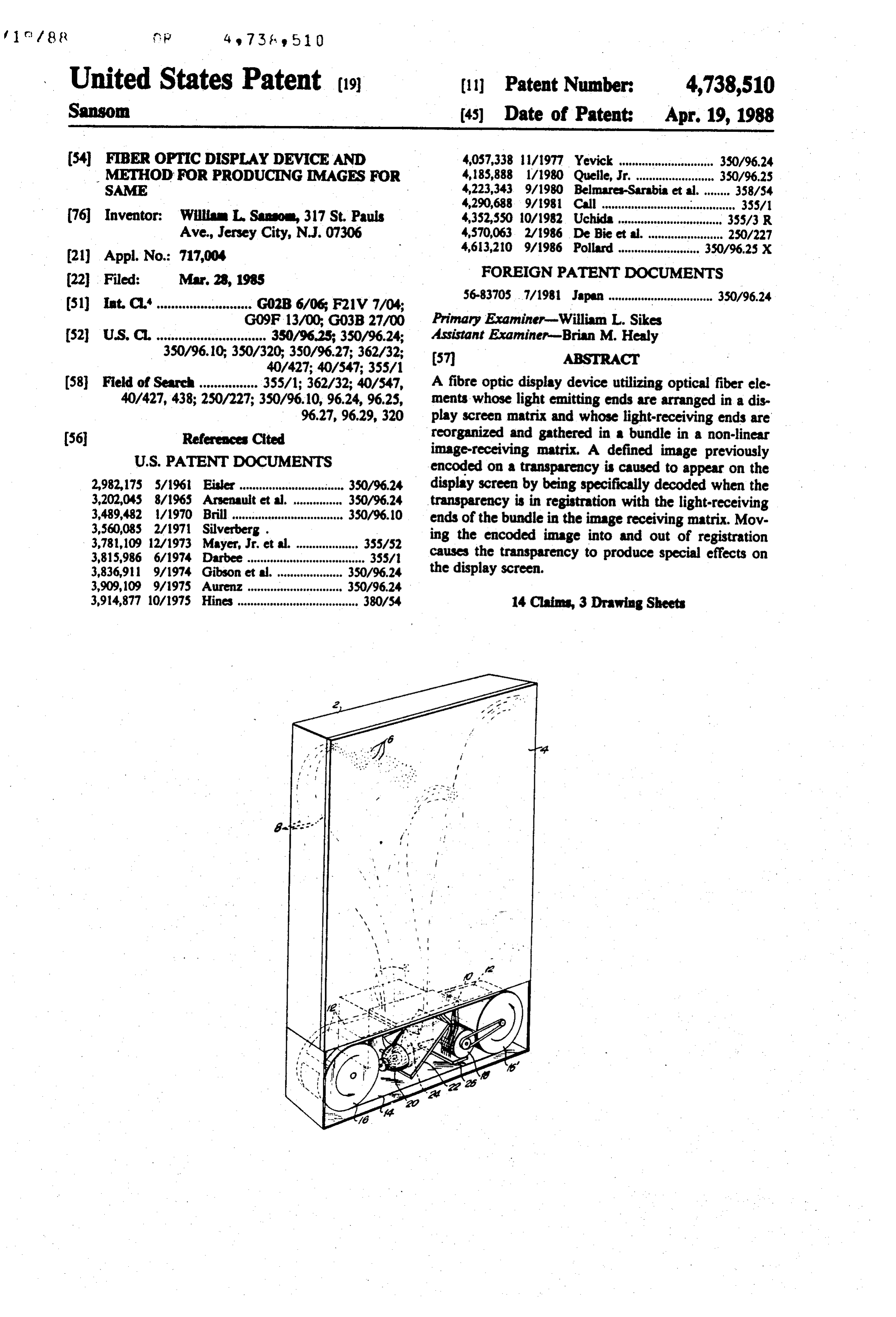
brought into registration, the next defined image is de to receive light and/or encoded images or other infor coded and suddenly snaps into view on the display face. mation projected therethrough. In another embodiment the optical fibers in the dis Encoded images are projected from beneath image play screen matrix are divided into sections or quad receiving matrix 10 through a series of transparencies 12 rants and preselected quadrants or individual fibers are carried by a continuous belt 14. These transparencies reorganized at the image-receiving matrix face to pro may be spacially separated on belt 14, as shown, or may vide for special effects, such as fade-in and fade-out, together form the belt itself. Belt 14 is mounted on two wipe-in and wipe-out, exploded and imploded images rotatable spindles 16 and 16 and driven by drive means and the like. 18, such as an electric motor, as known in the art. In this case the fibers in the bundle are reorganized in O Beneath belt 14, there is provided a source of light 20 a precise orderly fashion, each section or quadrant of which impinges on an angularly disposed dichroic mir the fibers in the display screen matrix being connected ror 22 to reflect light to the bottom of the transparencies in a coherent manner to a preselected portion of the 12 carried by belt 14 and to filter out infra-red light image-receiving matrix face to achieve the desired vi components. A fan25 is provided to remove heat gener sual effect. It is important to note in this connection that ated by light source 20.
there is a distinct difference between "non-coherent' It is important to provide control means for assuring bundles of fibers, which are randomly oriented, and that the encoded transparencies are accurately regis "reorganized” fiber bundles which are groups of "co tered with the light-receiving optical matrix 10 to pro herent' fibers.
In the context of this specification and claims, "reor 20 duce the desired decoded display on screen 4. Such control means is generally shown at 26 in FIG. 1, and ganized fibers" is intended to embrace and include non coherent bundles of fibers and parts of bundles which more FIG.
specifically in FIG. 2, also in schematic form.
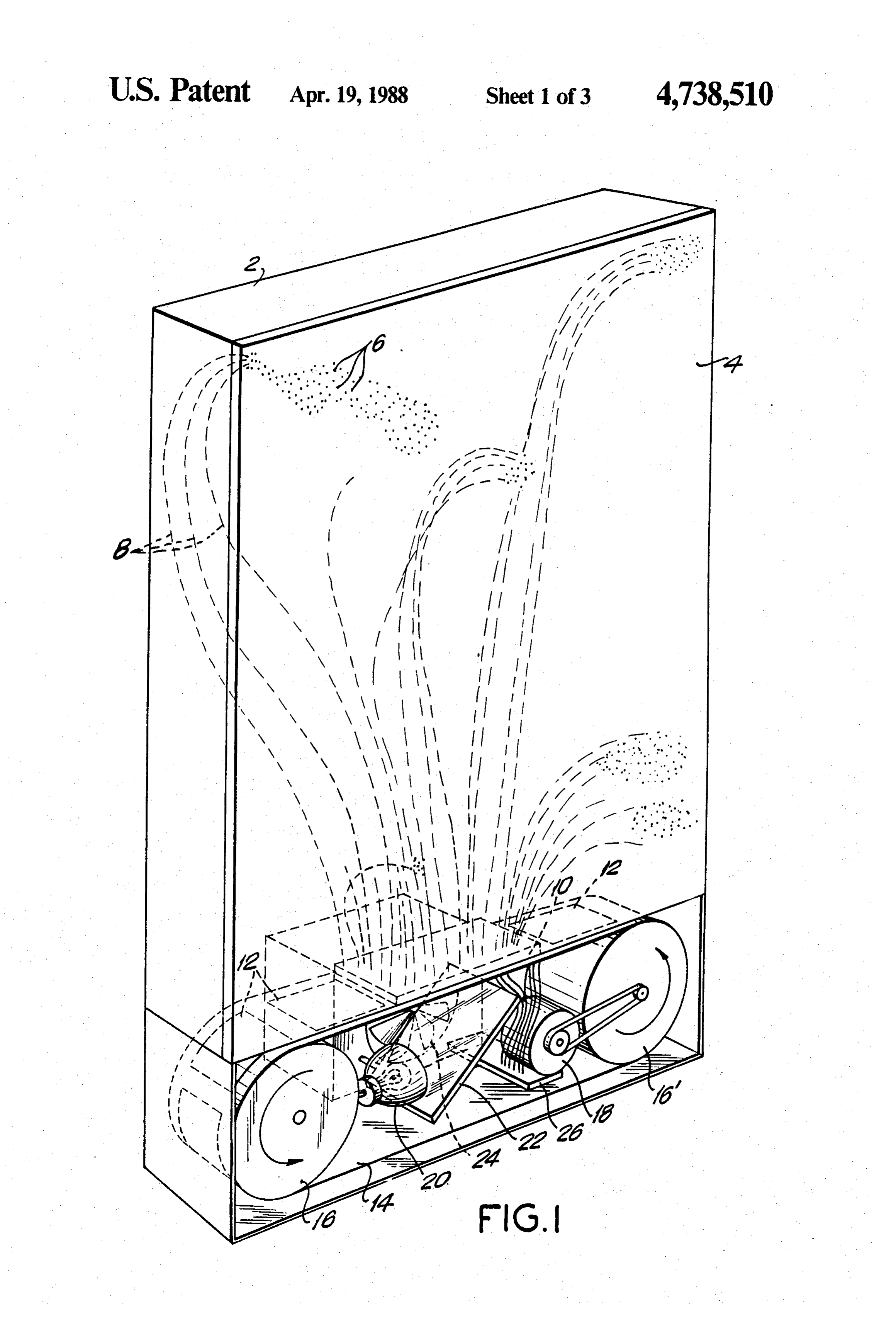
2 shows the belt 14 provided with a series of are reorganized but may be coherent in part.
In producing defined images and "special effects' transparent ling, for areas 28, 30 and 32 respectively, for control example, stop, start and speed. Whether any with reorganized fibers, the same procedure is used as particular one of these
areas will appear will depend outlined above with respect to non-coherent fibers. upon the programmed sequence
That is, the defined image is projected in reverse onto a Each area is disposed to register of the display desired. display screen or the equivalent and photographed at 20 which may be the same as used in thea source with display of light device the normally light-receiving ends of the normally in age-receiving matrix to produce a transparency. Move 30 of FIG. 1, such light being directed to such areas ment of the so-produced transparency before the pro through optical fibers 34, 36 and 38 beneath belt 14. Further optical fibers 40, 42 and 44 are disposed in jection matrix during normal projection will then pro registration with optical fibers 34, 36 and 38, respec duce the desired special effect. tively to direct corresponding signals to a microproces BRIEF DESCRIPTION OF THE DRAWINGS sor 46 or suitable control means as known in the art. The invention will best be understood by the follow odes microprocessor
The to detect the may be provided with photo di corresponding light signals transmit ing drawings and the description with respect thereto, ted, or photo diodes may be disposed adjacent belt 14 to wherein:
detect such signals and transmit the same to the micro
FIG. 1 is a schematic view of an optical fiber display processor.
device in accordance with the present invention. 40
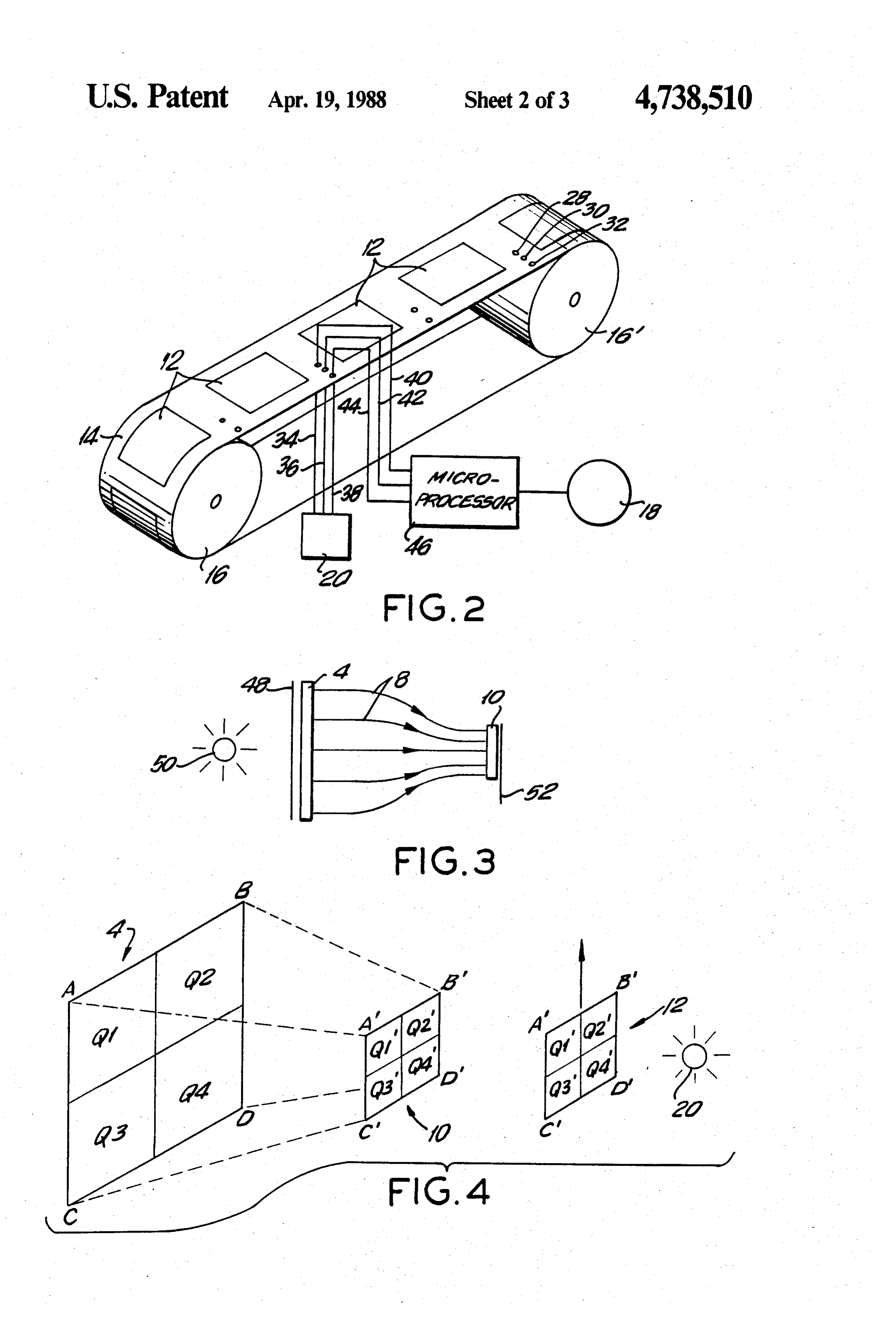
FIG. 3 illustrates a method of encoding defined in
FIG. 2 is a schematic view of an electrical system for ages for producing encoded transparencies 12 (FIGS. 1, controlling the operation of the device of FIG. 1;
FIG. 3 is a schematic view of a device for forming 2) by reverse projection of the desired images through transparencies of defined images to be projected the device of FIG. 1 or a part thereof. A transparency through the device of FIGS. 1 and 2. 45 48 provided with a desired image is placed between a FIG. 4 is a schematic view of an optical fiber display source of light 50 and the outer face of display screen 4 system showing use of coherent bundles of fibers for and the image is projected through the bundle of fibers illustrative purposes. 8 to the normal image-receiving matrix 10 and photo FIG. 5 is a schematic view of an optical fiber display graphed on a film 52 to produce an encoded transpar system for producing "special effects', namely an ex 50 ency 12 to be used as in FIG. 1.
plosion from the center of a display screen; The invention, as indicated above, provides a means FIG. 6 is a schematic view of an optical fiber display for projection of defined images onto an optical fiber system for producing an implosion from the corners of display screen in combination with "special effects' a display screen; and which are presented between such displays. These "spe FIG. 7 is a schematic view of an optical fiber display 55 cial effects" are in some instances achieved when the system for producing a "wipe-in' of a defined image on defined image is out of registration with the optical a display screen. fibers, thereby causing a scrambled image on the screen, Referring to FIG. 1 there is a schematically shown a but enabling a multitude of color and other visual ef housing 2 provided with an optical fiber display screen fects to hold viewer interest.
4, the outer viewing face of which comprises a multi To augment the "special effects', the optical fibers plicity of light emitting optical fiber ends 6, or fiber are reorganized between the display screen and the points, bonded together in a matrix to form the display normally image-receiving ends of the fibers and the Scree. source of light. By "reorganized' it is meant, in one Each fiber point is represented by an optical fiber exemplary sense, that the optical fibers are so arranged generally indicated as 8 forming a bundle of fibers ex 65 that they are divided into quadrants of coherent sec tending from the normally light emitting ends 6 to a tions which are made to produce "special effects" by normally image-receiving matrix 10, also provided with the manner in which they are disposed at the light re fiber points terminating beneath the matrix (not shown) ceiving ends thereof with respect to the display screen.
Page 7
For example, by reorganizing the optical fibers at the understanding of the present invention, as indicated light receiving ends thereof with respect to the display above.
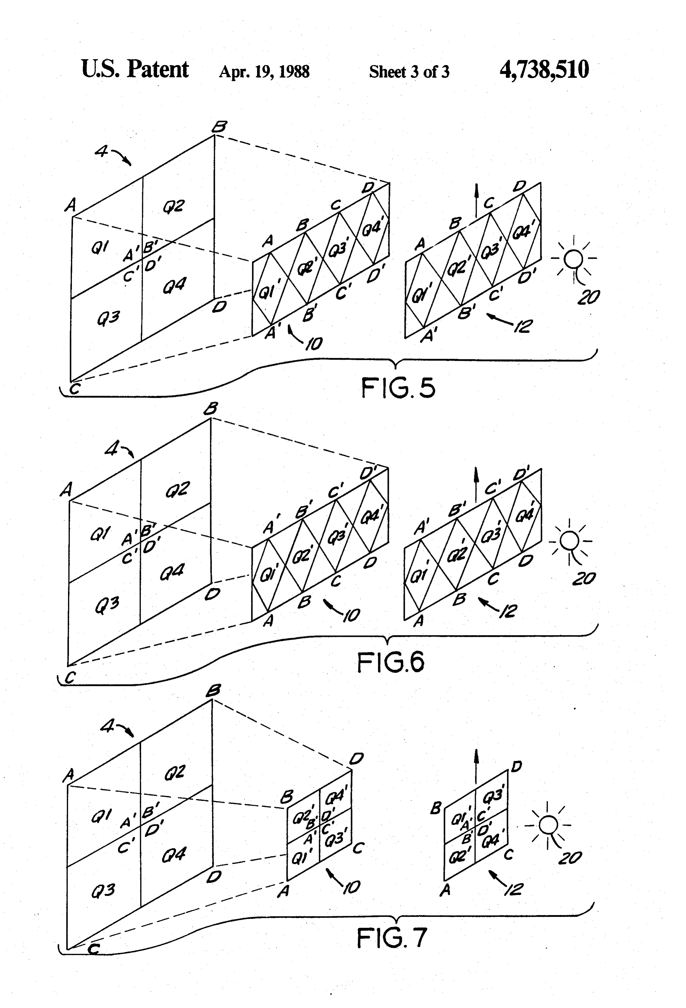
screen, it is possible to produce an exploded image oran FIG. 5 shows schematically how, by reorganization imploded image, a wipe-in or a wipe-out of an image or of coherent bundles of fibers, an explosive view of a a fade-in and fade-out of a defined image by selectively defined image can be produced from the center of dis reorientating the fibers. play screen 4. To accomplish this, the fibers from the This is accomplished by dividing the display screen respective quadrants of the display screen 4 are reorga into preselected areas shown only for illustrative pur nized and disposed in the projection matrix 10 as shown, poses as quadrants and by selectively reorienting the each point of the quadrants Q1-Q4 of the display screen fibers of each quadrant to affix the same to the matrix 10 being reorganized as quadrants Q1'-Q4 of image bonding the normally image-receiving ends thereof in receiving matrix 10, so that points A,B,C and D and such relationship as to achieve the desired special ef. A,B,C and D'are as indicated in the image-receiving fects. matrix 10 of FIG. 5. Then, when a photographed trans The foregoing is more specifically illustrated in parency 12 is made in reverse direction, the transpar FIGS. 4-7, wherein the image-receiving ends of the 15 ency will correspond to the encoded image transmitted optical fibers are so disposed on the light-receiving through the image-receiving matrix 10.
projection matrix as to receive progressive images or When transparency 12 is moved upward in FIG. 5, as indicated information from belt 14 as it passes beneath the light the defined by the arrow, and during normal projection of receiving ends of the fibers. By programmed reorgani transparencyimage, the points A,B,C and D' on the 12 will first register with the correspond zation of the light receiving ends of the optical fibers 20 with respect to selective quadrants of the display ma These ing points A-D' on the image-receiving matrix 10. trix, it is possible to cause the display to achieve differ points A,B,C and D'by virtue of corresponding ent visual effects as described above, prior to or after a also to the center of display screen 4, will start to regis defined image on a transparency 12 is registered with ter the image from transparency 12 and display the same the optical fibers at the image-receiving ends of the 25 from 12 the center of display screen 4 as the transparency progresses upwardly past light source 20, until the fibers.
For purpose of illustrating how certain "special ef. complete image on the transparency forms up on dis fects' can be achieved, but in no way limiting the multi play screen 4.
tude of possibilities of doing so, FIGS. 4-7 show in a In a similar manner, an implosion of a defined image simplistic and schematic manner various arrangements from the outer corners A-D of the display screen 4 can of reorganized fibers in coherent bundles to produce, be accomplished as shown in FIG. 6. In this case the respectively, an explosion of a defined image from the optical fiber bundles of the respective quadrants Q1-Q4 center of the display screen 4 (FIG. 5); at implosion of are so reorganized that the outermost points A,B,C,D of a defined image from the corners of the display screen 4 respective quadrants Q1-Q4 appear on the lower part of image-receiving matrix 10 and the upper part of trans
(FIG. 6); and a wipe-in of a defined image from the left 35 of the inside of display screen 4 (from the right of screen parency 12; and the innermost points A,B,C and D' of the quadrants of display screen 4 appear at correspond 4 as viewed from the outside thereof), as shown in FIG. ing points of image-receiving matrix 10 and transpar
As exemplified in FIGS. 4-7, the display screen 4 is ency 12, as shown in FIG. 6.
When transparency 12 is moved upwardly in the divided into four quadrants, designated as Q1, Q2, Q3 and Q4, respectively, (viewed from the inside). The direction of the arrow in FIG. 6, points A-D of trans parency 12 start to register with corresponding points outside corners of display screen 4 (also viewed from A-D the inside) are designated by corners A,B,C and D as cornersonA-D image-receiving matrix 10 from the outside and result in a completely defined image shown. The intersection of each quadrant at the center when the transparency 12 and the image-receiving ma of display screen 4 is designated by A, B, C and D', 45 also as illustrated. trix 10 are in registration. To produce the above described and other special special If it is desired to provide a "wipe-in" or a "wipe-out" effects, the optical fibers from each quadrant Q1-Q4 are the fibers effect, this can be accomplished by reorganizing reorganized and affixed in a coherent manner in the as shown in FIG. 7. In this figure a "wipe-in" image-receiving matrix 10. When a transparency is 50 is illustrated from left to right of the inside of display made, as described above, in a reverse direction from screen 4 (right to left as viewed from the outside of the normal image projection, the transparency will be in display screen).
conformity with the encoded image projected through Here, the fibers are so reorganized that when trans the reorganized fibers. parency 12 moves upwardly between light source 20 FIG. 4 is presented only to better understand the 55 and the image-receiving matrix 10, the defined image invention and illustrates schematically a system wherein starts to form up on the left (inside) of display screen 4 the display screen 4 is divided into four quadrants and continues across the screen to the right (inside) Q1-Q4 defined by corners A-D and the fibers from thereof until the transparency 12 is in complete registra each quadrant are coherently arranged in projection tion with image-receiving matrix 10, at which time the matrix 10 in corresponding quadrants Q1'-Q4 defined 60 complete image is displayed. In a similar manner a "wipe-out" may be accom by corners A-D'. When an encoded transparency 12 of plished simply by reversing the fiber reorganization, as an image is passed between projection matrix 10 and a source of light 20, in the direction of the arrow shown willIfbe apparent from the foregoing description. it is desired to "fade-in" or "fade-out" an image, in FIG, 4, an image will appear on display screen 4 when all quadrants of the transparency 12 and of image 65 this can be accomplished by reorganizing the normal receiving matrix 10 are in registration. This illustrates a light-receiving ends of the fiber bundle over the entire completely coherent optical fiber display system which face of the projection matrix 10, so that any light ob is described only for the purpose of enabling a better struction passing between light source 20 and projec
Page 8
tion matrix 10 will gradually dim the image on display one optical fiber having the other end thereof lo screen 4 until it fades out or causes the display screen to cated in the image-receiving matrix; brighten from no image until the image fades in. This is means to project a light-generated encoded image not possible when using an entirely coherent bundle of 5 a plurality onto said image-receiving matrix; and fibers, as illustrated in FIG. 4, wherein an image ob of encoded transparencies mounted on a struction passing between the light source 20 and pro movable means, means for moving said movable jection matrix 10 will simply result in a dark area pass means; each encoded transparency having an ing across display screen 4. image thereon which is reorganized in correspon More specifically, the reorganization of the fibers to 10 dence with said screen distinct areas such that as produce such a "fade-in" or "fade-out" is done in such said encoded transparency is moved in front of said manner that in each row of the light-receiving ends of image-receiving matrix the image formed on said the fibers there are located some fibers that correspond display screen is initially a variation of the true to various preselected sections over the display screen. image which can be a recognizable variation of the Consequently, as a dark portion of the film moves in a true image, and then said variation image becomes linear way across the light-receiving fiber matrix it the true image as said encoded transparency moves progressively blocks out a greater part of each section into complete registration with said image-receiv of the display screen matrix until the image fades out. ing matrix whereby to create optical wipes as said The fadeing-in of an image is accomplished in a similar, transparency moves into complete registration but reverse manner. from a non-registration position. 20 2. A device according to claim 1 wherein said means
The foregoing description of the manner in which "special effects' can be provided in accordance with to project a light-generated encoded image onto said image-receiving matrix comprises a rotatable belt pro this invention is only illustrative of the multitude of vided with photographic reorganized fiber arrays which can be made to accom defined images, and meanstransparencies to register of said encoded said images with plish the objects of this invention. 25
It should also be understood that resort may be had to the image-receiving ends of said optical fiber bundle, such modifications and equivalents as fall within the and light means to project said transparencies onto said image-receiving matrix.
spirit of the invention and the scope of the claims here 3. A device according to claim 1, wherin said means inafter made.
to project light-generated images onto said image 1. A fiber optic display device for creating optical receiving matrix comprises a rotatable belt provided wipes by projecting on a display screen programmed with photographic transparencies of encoded defined defined immobile images and undefined images com successively images and undefined images, and means to register prising: said encoded defined and undefined images a display screen matrix and an image-receiving ma 35 with the image-receiving ends of said optical fiber bun trix; dle to produce defined and undefined images on said display a plurality of optical fibers forming a bundle of fibers generated screen matrix, and light means to project light connected to and between and display screen ma images onto said image-receiving matrix. 4. A device trix and said image-receiving matrix, one end of able belt is connected according to claim 2, wherein said rotat said bundle of fibers being arranged in a two-di 40 trol to drive means actuated by con means for intermittently mensional array in said display screen matrix and ter a transparency of a preselected stopping said belt to regis the other end thereof being arranged in a two-di said image-receiving matrix. defined image with mensional array in said image-receiving matrix, the fiber ends in said image-receiving matrix being able 5. A device according to claim 3, wherein said rotat reorganized with respect to the fiber ends in said 45 trol meansbelt is connected to drive means actuated by con display screen matrix in non-linear fashion and ter a transparency for intermittently stopping said belt to regis reorganized such that the respective ends of said of a preselected defined image with fibers occupy different relative positions at said said6. image-receiving
A fiber optic matrix.
display device according to claim 1, image-receiving matrix and said display screen wherein said encoded defined matrix ends and being appropriately rearranged reversely projecting a primaryimages image are produced by onto the face of such that images received by said image-receiving said display screen matrix and through matrix are simultaneously displayed over pre fibers in a normally image-receiving matrix,reorganized and photo selected areas of said display screen matrix when graphing the same to produce an encoded transparency an image is in partial registration with said image of said image, whereby said light-generated encoded receiving matrix in a manner which can produce a 55 image directed onto said normally image-receiving ma recognizable variation of a true image prior to trix corresponds to the image on the transparency so complete registration between said image and said image receiving matrix fibers and encoded images produced. 7. A fiber optic display device according to claim 1, are decoded and simultaneously displayed as true wherein images over the entire display screen matrix when reverselysaid encoded defined images are produced by projecting a primary image onto the face of an immobile encoded image is in complete registra said display screen matrix and through reorganized tion with said image-receiving matrix so that said optical fibers are reorganized to produce optical fibers in a normally image-receiving matrix, and photo wipes as an image moves from partial to complete graphing the same to produce an encoded transparency registration with said image-receiving matrix fi 65 of said image, whereby said light-generated encoded bers, said display screen being divided into distinct image directed onto said normally image-receiving ma trix corresponds to the image on the transparency so areas and each such distinct area having at least one produced.
optical fiber connected thereto with said at least
Page 9
8. A device according to claim 1, wherein said en receiving matrix so that said optical fibers are reor coded image is projected onto said image-receiving ganized and can produce optical wipes as an image matrix by means for linearly moving, in sequence, suc moves from partial registration to complete regis cessive images provided by photographic tranparencies tration with said image-receiving matrix fiber ends; of said encoded images. 5 connecting one end of at least one fiber of the bundle 9. A method of generating optical wipes using a fiber of fibers to each area of the display screen matrix optic display device comprising: with the other end of said one fiber being located in providing a two-dimensional display screen matrix the image-receiving matrix; and a two-dimensional image-receiving matrix; preparing a plurality of transparencies, each having dividing the display screen matrix into a plurality of 10 an image thereon which is organized in correspon separate areas; dence with the various areas of said display screen providing a plurality of optical fibers forming a bun matrix such that as said encoded transparency is dle of fibers connected to and between said display moved in front of said image-receiving matrix the screen matrix and said image-receiving matrix; image formed on said display screen can initially be arranging first ends of said fibers in a two-dimen- 15 a recognizable variation of the true image, and then sional array in said display screen matrix and the said variation image can become the true image as other ends of said fibers in a two-dimensional array said encoded transparency moves into complete is said image-receiving matrix; registration with said image-receiving matrix to reorganizing the fiber ends in said image-receiving create optical wipes as said transparency moves array with respect to the fiber ends in said display 20 into complete registration from a non-registration screen array in non-linear fashion such that the position;
respective ends of said fibers occupy different rela moving each encoded transparency in front of the tive positions in said image-receiving array and in image-receiving matrix; and said display screen array and said fibers are appro projecting said encoded transparency onto said im priately rearranged such that images received by 25 age-receiving matrix.
said image-receiving matrix are simultaneously 10. The method defined in claim 9 wherein the optical displayed over pre-selected areas of said display wipes includes a fade-in and a fade-out. screen matrix when an image is in partial registra 11. The method defined in claim 9 wherein the optical tion with said image-receiving matrix in a manner wipes includes a wipe-in and a wipe-out. which can produce a recognizable variation of a 30 12. The method defined in claim 9 wherein the optical true image prior to complete registration between wipes includes an exploded image.
said image and said image-receiving matrix fiber 13. The method defined in claim 9 wherein the optical ends and encoded images are decoded and simulta wipes includes an imploded image.
neously displayed as a true image over the entire 14. The method defined in claim 9 wherein the optical display screen matrix when an immobile encoded 35 wipes includes a variation in brilliance. image is in complete registration with said image
Provenance
- Collection
- Cited prior art
- Original PDF
- patentimages.storage.googleapis.com →
- Filed
- 1985-03-28
- Pages
- 9
- Method
- pdftotext (the PDF's own text layer) + pdftoppm 300dpi page scans
- Source
- Google Patents bibliographic record
- Granted
- 1988-04-19
- Inventors
- William L. Sansom
- Transcribed from
- patentimages.storage.googleapis.com →