patent · US4076378
Tapered fiber optic array
28 February 1978
Page 1 — bibliographic record
VVV V a St.
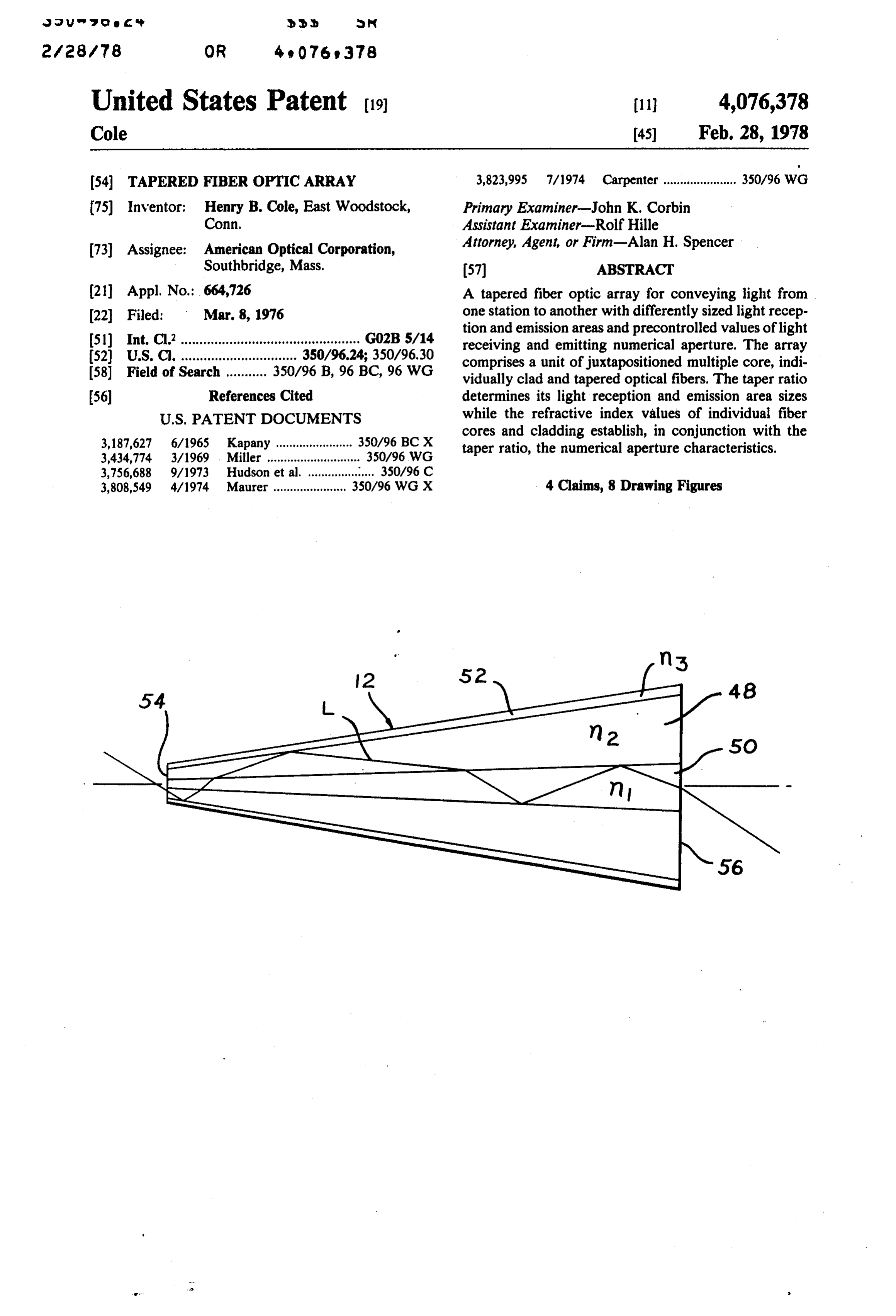
United States Patent (19) 11 4,076,378 Cole 45 Feb. 28, 1978 (54) TAPERED FIBER OPTCARRAY 3,823,995 7/1974 Carpenter ...................... 350/96 WG (75) Inventor: Henry B. Cole, East Woodstock, Primary Examiner-John K. Corbin Conn, Assistant Examiner-Rolf Hille 73 Assignee: American Optical Corporation, Attorney, Agent, or Firm-Alan H. Spencer Southbridge, Mass. 57 ABSTRACT (21) Appl. No.: 664,726 A tapered fiber optic array for conveying light from (22 Filed: Mar. 8, 1976 one station to another with differently sized light recep tion and emission areas and precontrolled values of light 51) Int. C.’................................................ GO2B 5/14 receiving and emitting numerical aperture. The array 52) U.S. C. ............................... 350/96.24; 350/96.30 comprises a unit of juxtapositioned multiple core, indi (58) Field of Search ........... 350/96 B, 96 BC, 96 WG vidually clad and tapered optical fibers. The taper ratio 56) References Cited determines its light reception and emission area sizes
cores and cladding establish, in conjunction with the 3,187,627 6/1965 Kapany ....................... 350/96 BC X taper ratio, the numerical aperture characteristics. 3,434,774 3/1969 . Miller ............................ 350/96 WG
3,808,549 4/1974 Maurer ...................... 350/96 WG X 4 Claims, 8 Drawing Figures
Page 2
Drawing sheet — no readable text.
Page 3
Drawing sheet — no readable text.
Page 4
TAPERED FIBER OPTIC ARRAY IN THE DRAWINGS
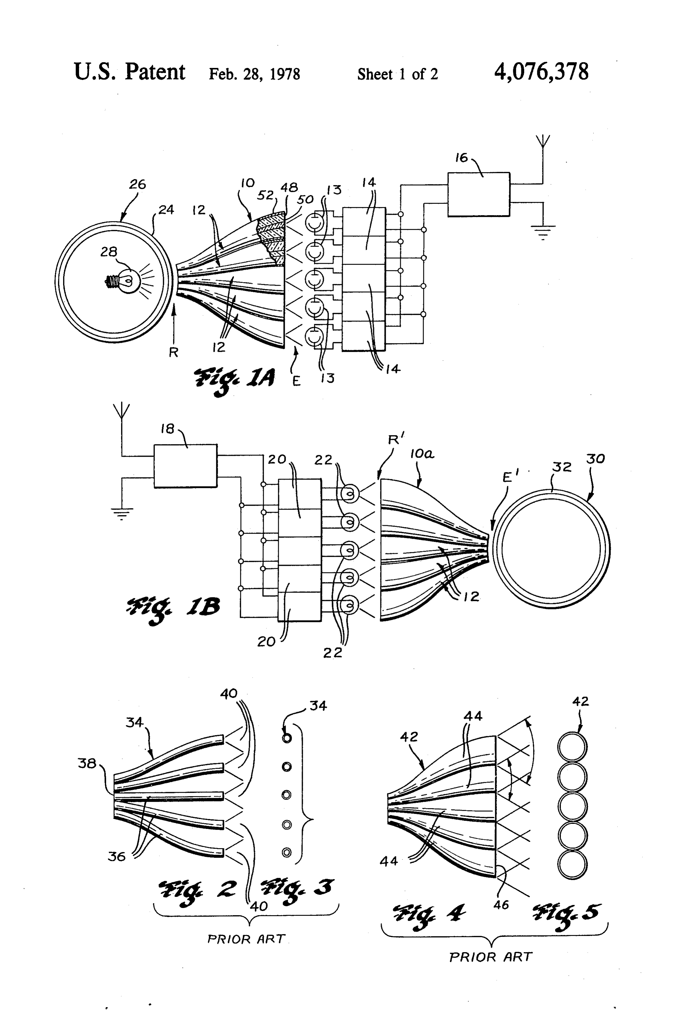
BACKGROUND OF THE INVENTION FIGS. 1A and B illustrate preferred embodiments of the invention (improved tapered fiber optic arrays) in , Field of the Invention 5 an exemplary application of use;
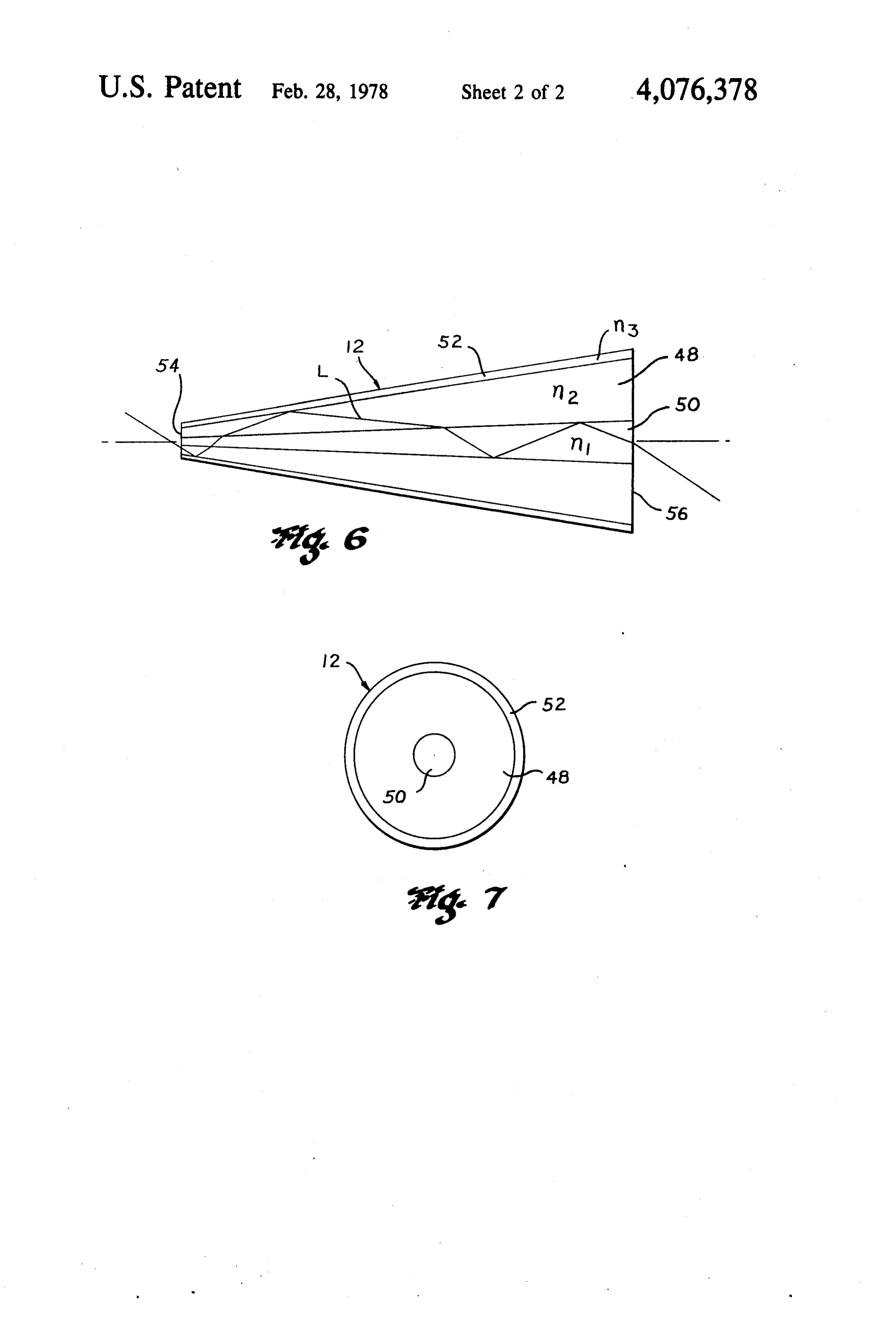
This invention relates to fiber optics and has particu FIGS. 2, 3, 4 and 5 are illustrations of pertinent prior lar reference to improvements in arrays of tapered opti art image-conducting devices, FIGS. 2 and 4 are plan cal fibers. views of arrays of aligned optical fibers and FIGS. 3 2. Discussion of the Prior Art and 5 are end views of the respective arrays; For the purpose of carrying light from a closely O FIG. 6 is a greatly enlarged cross-sectional view of a spaced array of light sources or illuminated image ele tapered optical fiber which is exemplary of the im ments to a relatively widely separated array, assemblies proved type used according to the invention; and of monofibers have a definite functional advantage over FIG. 7 is a view of the enlarged end of the fiber of the easier to manufacture assemblies of conventional F.G. 6.
tapered fibers; namely, the small size of the exit core 15 which prevents overlapping or intermixing of light or DESCRIPTION OF THE PREFERRED image elements in the separated array and/or waste of EMBODIMENTS emitted light by excessive spreading, Countering this Referring more particularly to FIGS. 1A and 1B advantage, however, are the difficulties, tediousness wherein, for purposes of better understanding the in and costliness involved in arranging and supporting 20 vention, there is illustrated tapered fiber optic arrays 10 numbers of monofibers with their corresponding one (FIG. 1A) and 10a (FIG. 1B) in an exemplary applica end tightly juxtapositioned and opposite ends spaced tion of use as image-element-conveying, separating or apart. Tapered fibers, on the other hand, which can be combining readily and efficiently joined into tightly juxtaposi elements aredevices carried wherein an array of image-forming from receiving stations RandR' to tioned relationship throughout their lenths for avoid 25 emitting stations E and E' respectively, ance of the aforesaid manufacturing problems, produce Arrays 10 and 10a are illustrated as being comprised relatively inefficient and/or inferior devices. of only five juxtapositioned tapered optical fibers 12, it While predetermined different spacings between cen ters of corresponding opposite ends of fibers in conven being or understood that less or more (i.e. several hundred thousand or more) such fibers may be used in each tional tapered arrays may be provided by selection of array according
to the needs of a particular application the taper ratio of the fibers or array, the large size of of use.
light exit core of each fiber, i.e. at the large end of the
With the device of combined FIGS. 1A and 1B being taper, causes the aforesaid adverse overlapping or inter schematically mixing of light or image elements and waste of emitted ing, transmitting illustrative of a picture facsimile produc light by excessive spreading. 35 and reproducing system, fibers 12 of Accordingly, the hitherto need to make a choice array 10 each receive an element of an illuminated between ungainly assemblies of monofibers with their image at station R and convey the image element to difficulties and costliness of manufacture and conven station E whereat photodetectors 12 individually each tional more compact and easily manufactured multifiber receive the light of one image element for conversion tapers with their drawbacks of relatively inefficient 40 into an electrical signal of an amplitude corresponding light or image element emission has, heretofore, left to that of the intensity of light received thereby. In the much to be desired in the art. particular system of FIGS. 1A and 1B which is used for With a view to overcoming the aforesaid and corol purposes of illustration only, electrical signals from lary drawbacks or disadvantages of prior art fiber optic photodetectors 12 are individually amplified by amplifi image-expanding or image-element-separating systems, 45 ers 14 and transmitted by wireless transmitter 16 to the present invention provides the improvement in a receiver 18 (FIG. 1B). The electrical signals being tapered fiber optic array wherewith the taper ratio of therein separated and individually amplified by amplifi the array as a whole can be selected to provide the ers 20 energize illuminators 22 (e.g. electrical lamps or desired image element spacing along with simultaneous light-emitting diodes) at receiving station R. Optical control of numerical aperture. 50 fiber array 10a then conveys the signal received from
SUMMARY OF THE INVENTION
illuminators 22 to emitting station E'. In the case of fascimile picture image transmission, a photographic
The invention accomplishes the foregoing objective transparency 24 placed upon drum 26 (FIG. 1A) and through the provision of a tapered fiber optic array illuminated by light source 28 may be scanned by rota formed of a plurality of juxtapositioned fibers in which 55 tion of drum 26 and/or lateral movement of optical each fiber has a plurality of cores of differing indices of fiber array 10 wherewith array 10 will mosaically re refraction and an outer cladding of a lower refractive ceive elements of the photographic image for transmit index than that of the cores. The provision of more than tance as just described. The reproduction or fascimile the conventional single core per fiber modifies the be image may be formed by means of a similar drum 30 havior of light traveling therethrough, making it possi (FIG. 1B) having a photosensitive paper thereon. Rota ble to provide independent control over numerical ap tion of drum 30 and/or lateral movement of optical erture and magnification. A tapered fiber may be de fiber array 10A in speeds and directions corresponding signed so that light entering one or more of its cores at to those of drum 26 and array 10 during the transmission its smallest end will exit from only the innermost core at of signals from transmitter 16 will produce the fas the larger end of the taper. 65 cimile.
Details of the invention will become more readily Those interested in greater details of systems of the apparent from the following description when taken in type shown in FIGS. 1A and 1B may refer to U.S. Pat. conjunction with the accompanying drawings. No. 1,751,584.
Page 5
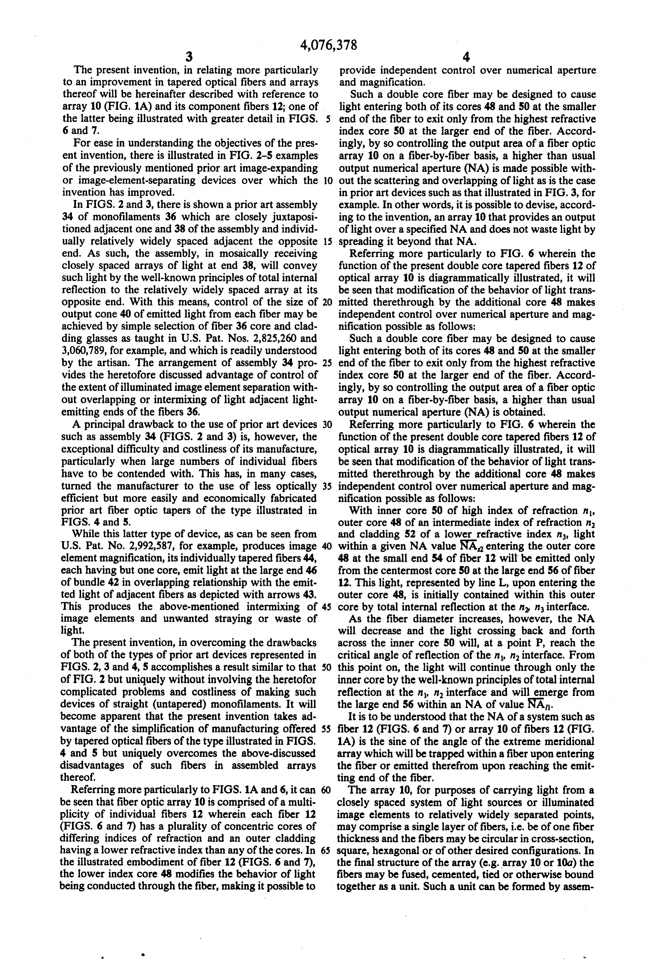
The present invention, in relating more particularly provide independent control over numerical aperture to an improvement in tapered optical fibers and arrays and magnification.
thereof will be hereinafter described with reference to Such a double core fiber may be designed to cause array 10 (FIG. 1A) and its component fibers 12; one of light entering both of its cores 48 and 50 at the smaller the latter being illustrated with greater detail in FIGS. 5 end of the fiber to exit only from the highest refractive 6 and 7. index core 50 at the larger end of the fiber. Accord For ease in understanding the objectives of the pres ingly, by so controlling the output area of a fiber optic ent invention, there is illustrated in FIG. 2-5 examples array 10 on a fiber-by-fiber basis, a higher than usual of the previously mentioned prior art image-expanding output numerical aperture (NA) is made possible with or image-element-separating devices over which the 10 out the scattering and overlapping of light as is the case invention has improved. in prior art devices such as that illustrated in FIG. 3, for In FIGS. 2 and 3, there is shown a prior art assembly example. In other words, it is possible to devise, accord 34 of monofilaments 36 which are closely juxtaposi ing to the invention, an array 10 that provides an output tioned adjacent one and 38 of the assembly and individ of light over a specified NA and does not waste light by ually relatively widely spaced adjacent the opposite 15 spreading it beyond that NA.
end. As such, the assembly, in mosaically receiving Referring more particularly to FIG. 6 wherein the closely spaced arrays of light at end 38, will convey function of the present double core tapered fibers 12 of such light by the well-known principles of total internal optical array 10 is diagrammatically illustrated, it will reflection to the relatively widely spaced array at its be seen that modification of the behavior of light trans opposite end. With this means, control of the size of 20 mitted therethrough by the additional core 48 makes output cone 40 of emitted light from each fiber may be independent control over numerical aperture and mag achieved by simple selection of fiber 36 core and clad nification possible as follows:
ding glasses as taught in U.S. Pat. Nos. 2,825,260 and Such a double core fiber may be designed to cause 3,060,789, for example, and which is readily understood light entering both of its cores 48 and 50 at the smaller by the artisan. The arrangement of assembly 34 pro- 25 end of the fiber to exit only from the highest refractive vides the heretofore discussed advantage of control of index core 50 at the larger end of the fiber. Accord the extent of illuminated image element separation with ingly, by so controlling the output area of a fiber optic out overlapping or intermixing of light adjacent light array 10 on a fiber-by-fiber basis, a higher than usual emitting ends of the fibers 36. output numerical aperture (NA) is obtained, A principal drawback to the use of prior art devices 30 Referring more particularly to FIG. 6 wherein the such as assembly 34 (FIGS. 2 and 3) is, however, the function of the present double core tapered fibers 12 of exceptional difficulty and costliness of its manufacture, optical array 10 is diagrammatically illustrated, it will particularly when large numbers of individual fibers be seen that modification of the behavior of light trans have to be contended with. This has, in many cases, mitted therethrough by the additional core 48 makes turned the manufacturer to the use of less optically 35 independent control over numerical aperture and mag efficient but more easily and economically fabricated nification possible as follows:
prior art fiber optic tapers of the type illustrated in With inner core 50 of high index of refraction n, FIGS. 4 and 5. outer core 48 of an intermediate index of refraction in While this latter type of device, as can be seen from and cladding 52 of a lower refractive index ns, light U.S. Pat. No. 2,992,587, for example, produces image 40 within a given NA value NA entering the outer core element magnification, its individually tapered fibers 44, 48 at the small end 54 of fiber 12 will be emitted only each having but one core, emit light at the large end 46 from the centermost core 50 at the large end 56 of fiber of bundle 42 in overlapping relationship with the emit 12. This light, represented by line L, upon entering the ted light of adjacent fibers as depicted with arrows 43. outer core 48, is initially contained within this outer This produces the above-mentioned intermixing of 45 core by total internal reflection at the n n interface. image elements and unwanted straying or waste of As the fiber diameter increases, however, the NA light. will decrease and the light crossing back and forth The present invention, in overcoming the drawbacks across the inner core 50 will, at a point P, reach the of both of the types of prior art devices represented in critical angle of reflection of the n n interface. From FIGS. 2, 3 and 4, 5 accomplishes a result similar to that 50 this point on, the light will continue through only the of FIG. 2 but uniquely without involving the heretofor inner core by the well-known principles of total internal complicated problems and costliness of making such reflection at the n n interface and will emerge from devices of straight (untapered) monofilaments. It will the large end 56 within an NA of value NA. become apparent that the present invention takes ad It is to be understood that the NA of a system such as vantage of the simplification of manufacturing offered 55 fiber 12 (FIGS. 6 and 7) or array 10 of fibers 12 (FIG. by tapered optical fibers of the type illustrated in FIGS. 1A) is the sine of the angle of the extreme meridional 4 and 5 but uniquely overcomes the above-discussed array which will be trapped within a fiber upon entering disadvantages of such fibers in assembled arrays the fiber or emitted therefrom upon reaching the emit thereof. ting end of the fiber.
Referring more particularly to FIGS. 1A and 6, it can The array 10, for purposes of carrying light from a be seen that fiber optic array 10 is comprised of a multi closely spaced system of light sources or illuminated plicity of individual fibers 12 wherein each fiber 12 image elements to relatively widely separated points, (FIGS. 6 and 7) has a plurality of concentric cores of may comprise a single layer of fibers, i.e. be of one fiber differing indices of refraction and an outer cladding thickness and the fibers may be circular in cross-section, having a lower refractive index than any of the cores. In 65 square, hexagonal or of other desired configurations. In the illustrated embodiment of fiber 12 (FIGS. 6 and 7), the final structure of the array (e.g. array 10 or 10a) the the lower index core 48 modifies the behavior of light fibers may be fused, cemented, tied or otherwise bound being conducted through the fiber, making it possible to together as a unit. Such a unit can be formed by assem
Page 6
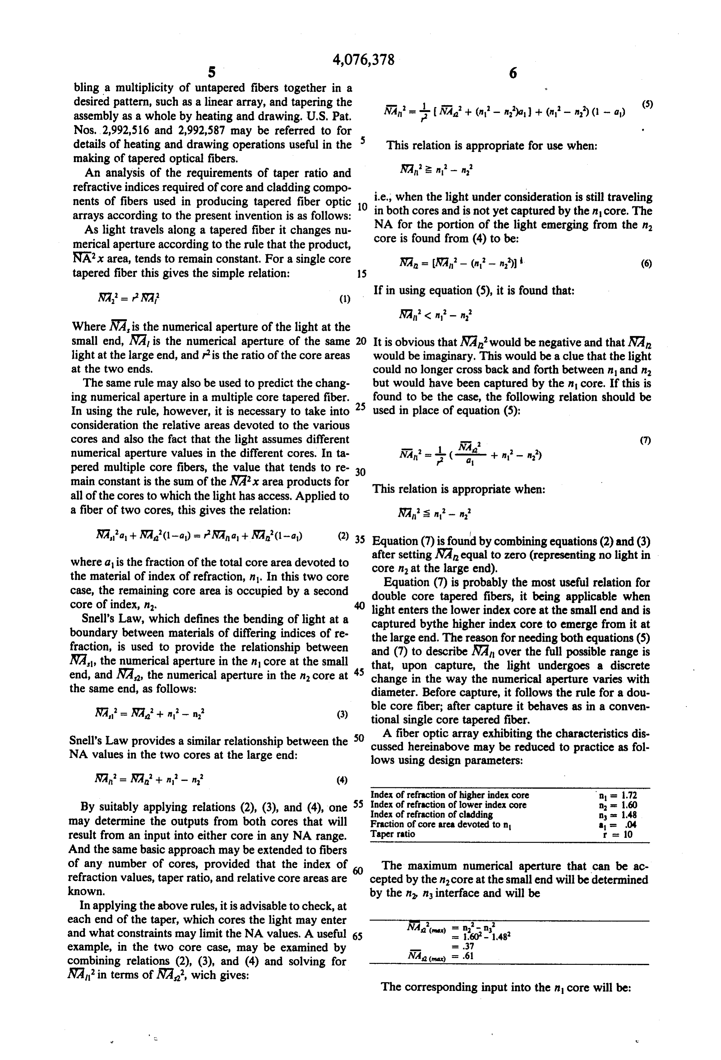
bling a multiplicity of untapered fibers together in a desired pattern, such as a linear array, and tapering the assembly as a whole by heating and drawing. U.S. Pat. NA* = - 2 (NA+ (n-na) + (n-n) (1 - a) (5)
details of heating and drawing operations useful in the 5 This relation is appropriate for use when: making of tapered optical fibers.
An analysis of the requirements of taper ratio and 2. n - n refractive indices required of core and cladding compo nents of fibers used in producing tapered fiber optic 10 i.e., when the light under consideration is still traveling arrays according to the present invention is as follows: in both cores and is not yet captured by the nicore. The As light travels along a tapered fiber it changes nu NA for the portion of the light emerging from the n merical aperture according to the rule that the product, core is found from (4) to be:
NAx area, tends to remain constant. For a single core NA = NA- (n-n) (6) tapered fiber this gives the simple relation: 15
NA* = r NA? (1) If in using equation (5), it is found that: NAC n-n
Where NA, is the numerical aperture of the light at the small end, NA is the numerical aperture of the same 20 It is obvious that NA would be negative and that NA light at the large end, and ris the ratio of the core areas would be imaginary. This would be a clue that the light at the two ends. could no longer cross back and forth between n and in The same rule may also be used to predict the chang but would have been captured by the nicore. If this is ing numerical aperture in a multiple core tapered fiber. 25 found to be the case, the following relation should be In using the rule, however, it is necessary to take into used in place of equation (5):
consideration the relative areas devoted to the various cores and also the fact that the light assumes different (7) numerical aperture values in the different cores. In ta pered multiple core fibers, the value that tends to re 30 main constant is the sum of the NAx area products for all of the cores to which the light has access. Applied to This relation is appropriate when: a fiber of two cores, this gives the relation: NA's n-n
NA’a + NA(1-a) = r NAa+ NA(1-a) (2) 35 Equation (7) is found by combining equations (2) and (3) after setting NA equal to zero (representing no light in where a is the fraction of the total core area devoted to core n at the large end).
the material of index of refraction, n. In this two core Equation (7) is probably the most useful relation for case, the remaining core area is occupied by a second double core tapered fibers, it being applicable when
Snell's Law, which defines the bending of light at a captured bythe light enters lower index core at the small end and is the higher index core to emerge from it at boundary between materials of differing indices of re the large end. The reason for needing both equations (5) fraction, is used to provide the relationship between and (7) to describe NAn over the full possible range is NA, the numerical aperture in the nicore at the small that, upon capture, the light undergoes a discrete end, and NA, the numerical aperture in the n, core at 45 change in the way the numerical aperture varies with the same end, as follows: diameter. Before capture, it follows the rule for a dou
(3) tional core fiber; after capture it behaves as in a conven single core tapered fiber.
A fiber optic array exhibiting the characteristics dis
Snell's Law provides a similar relationship between the 50 cussed hereinabove
NA values in the two cores at the large end: may be reduced to practice as fol lows using design parameters:
Index of refraction of higher index core n = 1.72
By suitably applying relations (2), (3), and (4), one 55 Index
Index of refraction of lower index core of refraction of cladding
may determine the outputs from both cores that will Fraction of core area devoted to in a = 04 result from an input into either core in any NA range. Taper ratio r is 10 And the same basic approach may be extended to fibers of any number of cores, provided that the index of 60 The maximum numerical aperture that can be ac refraction values, taper ratio, and relative core areas are cepted by the incore at the small end will be determined known. by the n n interface and will be In applying the above rules, it is advisable to check, at each end of the taper, which cores the light may enter NA " = n in .432 and what constraints may limit the NA values. A useful 65 example, in the two core case, may be examined by - .37 combining relations (2), (3), and (4) and solving for NAa () = .61
NA’ in terms of NA, wich gives:
The corresponding input into the nicore will be:
Page 7
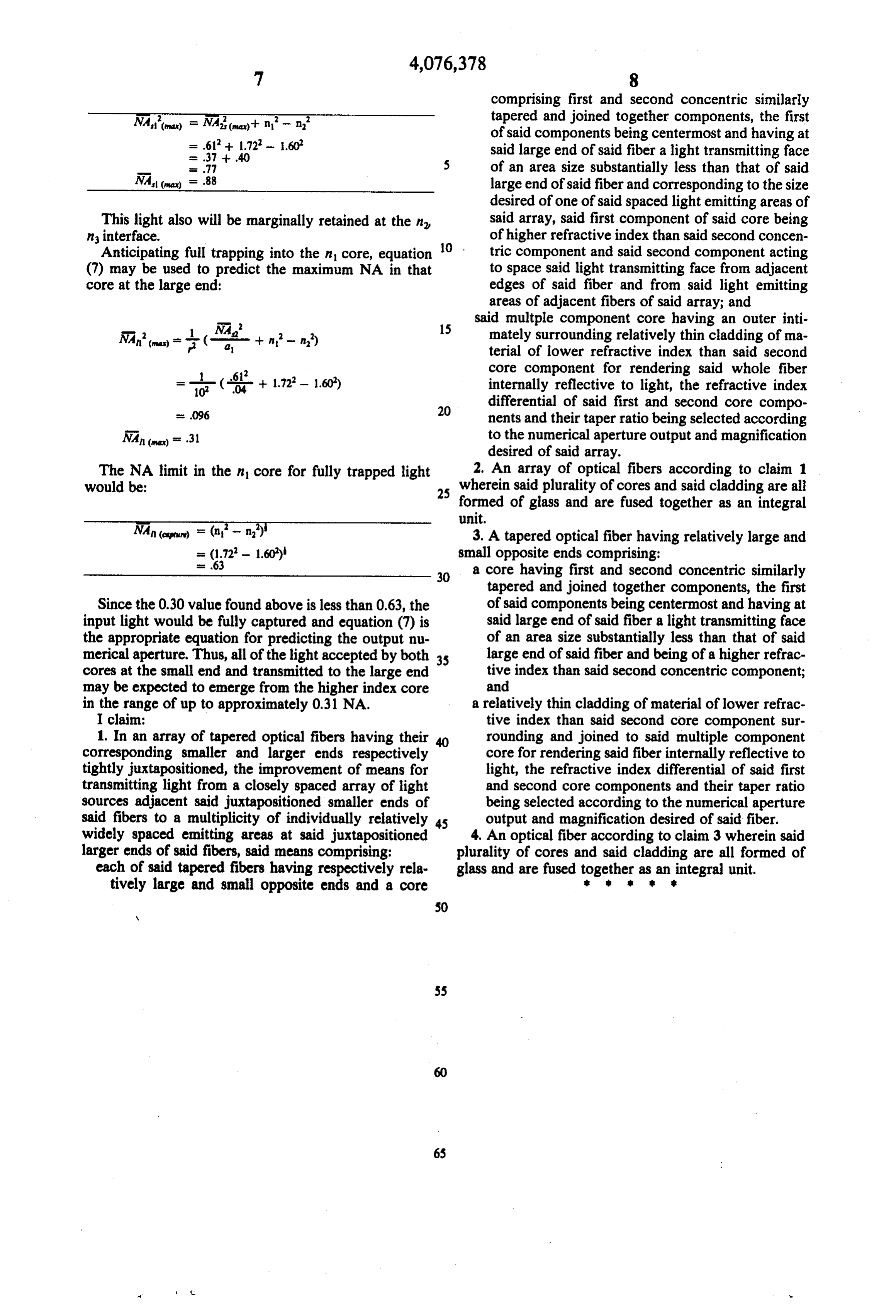
comprising first and second concentric similarly tapered and joined together components, the first of said components being centermost and having at .61 + 1.72 - 1.60 said large end of said fiber a light transmitting face
77 of an area size substantially less than that of said NA (raw) 88 large end of said fiber and corresponding to the size desired of one of said spaced light emitting areas of
This light also will be marginally retained at the n said array, said first component of said core being ninterface. of higher refractive index than said second concen Anticipating full trapping into the n core, equation O . tric component and said second component acting (7) may be used to predict the maximum NA in that to space said light transmitting face from adjacent core at the large end: edges of said fiber and from said light emitting areas of adjacent fibers of said array; and said multiple component core having an outer inti
15 mately surrounding relatively thin cladding of ma terial of lower refractive index than said second core component for rendering said whole fiber
1.722- 1.60) internally reflective to light, the refractive index
differential of said first and second core compo nents and their taper ratio being selected according
NA (wax) 31 to the numerical aperture output and magnification desired of said array.
The NA limit in the nicore for fully trapped light 2. An array of optical fibers according to claim 1 would be: 25 wherein said plurality of cores and said cladding are all formed of glass and are fused together as an integral unit.
3. A tapered optical fiber having relatively large and
(1.72 - 1.60) small opposite ends comprising:
30 a core having first and second concentric similarly tapered and joined together components, the first
Since the 0.30 value found above is less than 0.63, the of said components being centermost and having at input light would be fully captured and equation (7) is said large end of said fiber a light transmitting face the appropriate equation for predicting the output nu of an area size substantially less than that of said merical aperture. Thus, all of the light accepted by both 35 large end of said fiber and being of a higher refrac cores at the small end and transmitted to the large end tive index than said second concentric component; may be expected to emerge from the higher index core and in the range of up to approximately 0.31 NA. a relatively thin cladding of material of lower refrac I claim: tive index than said second core component sur 1. In an array of tapered optical fibers having their 40 rounding and joined to said multiple component corresponding smaller and larger ends respectively core for rendering said fiber internally reflective to tightly juxtapositioned, the improvement of means for light, the refractive index differential of said first transmitting light from a closely spaced array of light and second core components and their taper ratio sources adjacent said juxtapositioned smaller ends of being selected according to the numerical aperture said fibers to a multiplicity of individually relatively is output and magnification desired of said fiber. widely spaced emitting areas at said juxtapositioned 4. An optical fiber according to claim 3 wherein said larger ends of said fibers, said means comprising: plurality of cores and said cladding are all formed of each of said tapered fibers having respectively rela glass and are fused together as an integral unit. tively large and small opposite ends and a core
Provenance
- Collection
- Cited prior art
- Original PDF
- patentimages.storage.googleapis.com →
- Filed
- 1976-03-08
- Pages
- 7
- Method
- pdftotext (the PDF's own text layer) + pdftoppm 300dpi page scans
- Source
- Google Patents bibliographic record
- Granted
- 1978-02-28
- Inventors
- Henry B. Cole; American Optical Corp
- Transcribed from
- patentimages.storage.googleapis.com →