patent · US4332439
Method of producing a light conductor
1 June 1982
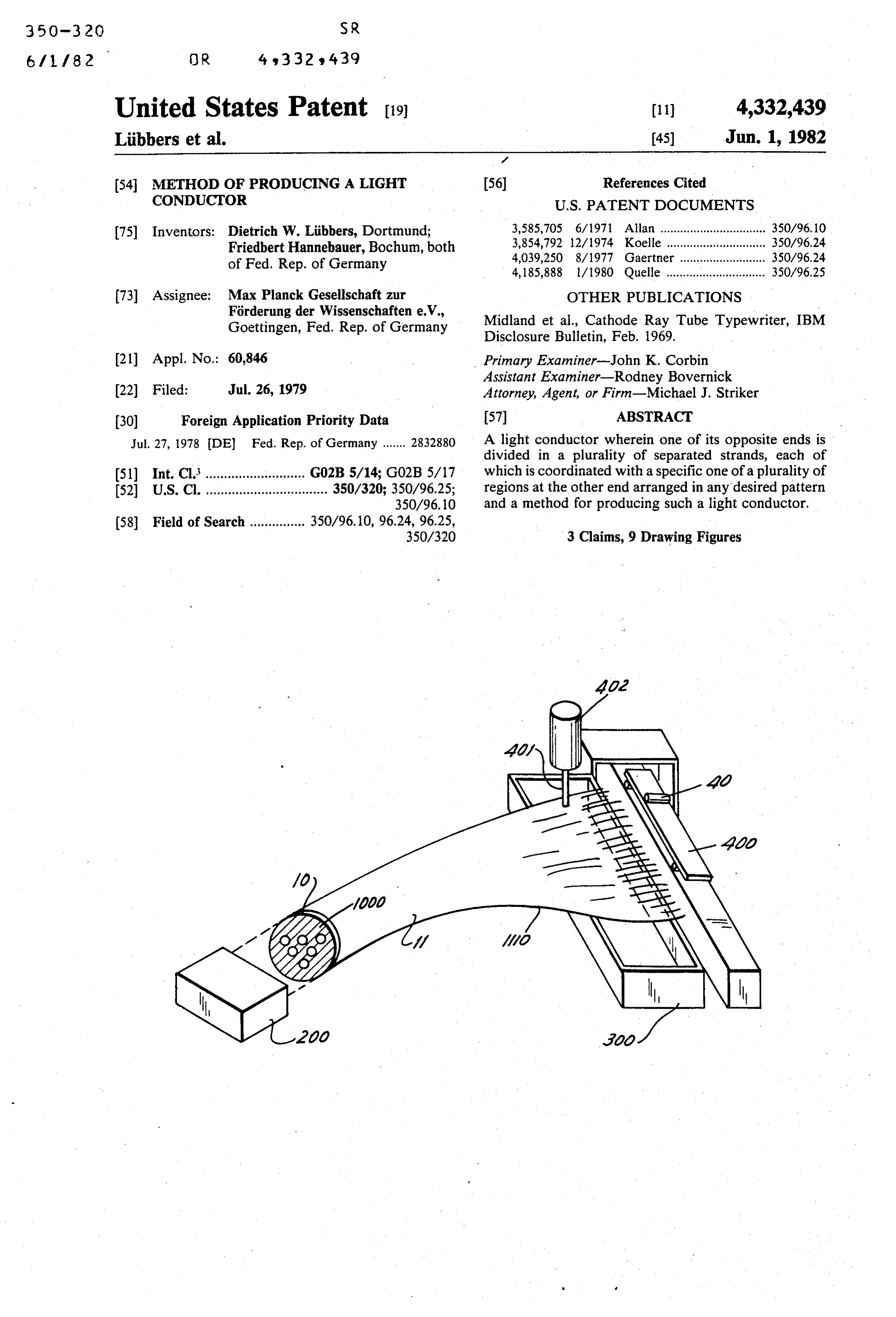
Page 1 — bibliographic record
United States Patent (19) 11) 4,332,439 Libbers et al. 45) Jun. 1, 1982
54 METHOD OF PRODUCING A LIGHT 56) References Cited CONDUCTOR U.S. PATENT DOCUMENTS (75) Inventors: Dietrich W. Libbers, Dortmund; 3,585,705 6/1971 Allan ................................ 350/96.10 Friedbert Hannebauer, Bochum, both 3,854,792 12/1974 Koelle .............................. 350/96.24 of Fed. Rep. of Germany 4,039,250 8/1977 Gaertner .......................... 350/96.24 4,185,888 l/1980 Quelle .............................. 350/96.25 73) Assignee: Max Planck Gesellschaft zur OTHER PUBLICATIONS Forderung der Wissenschaften e.V., Midland et al., Cathode Ray Tube Typewriter, IBM Goettingen, Fed. Rep. of Germany Disclosure Bulletin, Feb. 1969.
(21) Appl. No.: 60,846 Primary Examiner-John K. Corbin Assistant Examiner-Rodney Bovernick 22 Filed: Jul. 26, 1979 Attorney, Agent, or Firm-Michael J. Striker (30) Foreign Application Priority Data 57 ABSTRACT Jul. 27, 1978 DEl Fed. Rep. of Germany ....... 2832880 A light conductor wherein one of its opposite ends is divided in a plurality of separated strands, each of 51) Int. Cl............................ G02B 5/14; G02B5/17 which is coordinated with a specific one of a plurality of 52 U.S. Cl. ................................. 350/320; 350/96.25; regions at the other end arranged in any desired pattern 350/96.10 and a method for producing such a light conductor.
Page 2
Drawing sheet — no readable text.
Page 3
Drawing sheet — no readable text.
Page 4
Drawing sheet — no readable text.
Page 5
The other end of the light conductor may be subdi
METHOD OF PRODUCING A LIGHT vided into only two different elementary areas with CONDUCTOR which predetermined geometric outlines of the object may be illuminated and the reflection of these outlines
BACKGROUND OF THE INVENTION 5 may be measured. The two different areas may have a The present invention relates to a light conductor in be random distribution, or one of the elementary areas may which at least one of the ends thereof is divided into a distributed according to a specific function. Thereby plurality of individual strands. it is for instance possible to compensate for a certain It is known to use light conductors for the purpose to brightness distribution of the light source. The two different elementary areas may be formed adapt light sources of predetermined geometrical con O from fibers of different materials, for instance glass struction to light receivers of different geometrical con fibers and quartz fibers, in which the glass fibers are struction in such a manner that the outer boundary of used for guiding the light from the light source to the the two ends of the light conductor are constructed in receiver and the quartz fibers for the return guiding of such a manner that they correspond respectively to the 5 the geometrical shape of the light source and the receiver. rial may so light
that the filter action of the respective mate used.
This is possible in that the individual fibers of the light conductor are arranged substantially randomly adjacent from fibers ofisdifferent
Finally, it also possible to form the different areas each other and be subsequently connected to each other to the spatial structure isdiameters possible. so that a filtering due in such a manner so that the connected ends may be 20 It may also be of advantage when the two different adapted to the geometric form of light source and light areas are arranged in a repeating pattern since thereby receiver, respectively. an optimal relationship of guiding the light in the one This known type of light conductor is, however, not and the opposite direction to and from a predetermined suitable to solve the problem which arises when certain object may be obtained.
regions of an object are illuminated by discrete light 25 The present invention relates also to a method for sources or if certain regions are illuminated by a light producing a light conductor according to the present source and the reflective light has to be returned to a invention. The method according to the present inven receiver. tion comprises the steps of placing a mask onto the SUMMARY OF THE INVENTION other end of the light conductor, having first specific 30 but at random arranged areas which are translucent,
It is an object of the present invention to provide a whereas the remaining area of the mask is opaque, illu light conductor which solves the above-mentioned minating the mask covered end with at least one illumi problem. nating device, separating the light carrying fibers from With this and other objects in view, which will be the non-light carrying fibers at the one end, and con come apparent as the description proceeds, the light 35 necting the light carrying fibers, respectively the non conductor of the present invention has opposite ends light carrying fibers, into separate strands. and at least one of the opposite ends is divided into a The advantages of the method according to the pres plurality of strands and wherein each strand of the one ent invention consist that, for instance by photographi end is coordinated with a specific but randomly ar cally produced masks, very fine regions and contours ranged region of the other end. may be produced and such masks are connected over The advantage of this light conductor according to the other end of the light conductor and the separation the present invention is that each area at the other end of the respective light carrying fibers may be carried may perform a function independent from the other out either by hand or by means of a photoelectric cell 33. controlled device.
This is especially of importance if the other end face 45 According to a further development of the method of of the light conductor is subdivided into a plurality of the present invention the mask at the other end of the different elementary areas and wherein each strand of light conductor may be optically produced. This has the the one end is coordinated with a specific area of the advantage that no separate masks may be produced for other end, each desired pattern.
In this way it is, for instance, possible to produce with 50 If especially exact masks are required then these certain fibers of the light conductors a finely distributed masks may be formed by films extending over and light pattern onto an object and to guide the reflected fixedly connected to the other end of the light conduc rays through other adjacent fibers to a receiver. In this tor.
way an optimal use of receiver, light source and reflec In this case it is especially advantageous if the masks tive characteristics of the objects is possible. 55 are produced by photoetching. Especially advantageous is if the elementary areas are The mask covered end may be illuminated with a combined into closed regions when a predetermined plurality of illuminating devices and the plurality of pattern on the surface of the object is illuminated and illuminating devices may be constructed, for respec reflections thereof are to be measured. The total light tively emanating light of different color, whereby it is emanating from the light source illuminates then only possible to use different color sensitive receivers to the predetermined pattern and the total reflected light thereby automate the separation of the fibers. may be returned through the other remaining fibers. Another possibility exists in that one or a plurality of According to a further development of the present illuminating devices are provided from which a light invention the elementary areas form lines. In this way it ray of substantially punctiform cross-section emanates is possible to form outlines of a fineness up to the resolu 65 with which the end face of the other light conductor tion of the light conductor, that is of a fineness which end may be scanned in a programmed manner. With this may reach up to the diameter of the individual fibers method it is possible to separate fibers arranged in a from which the light conductor is composed. very complicated pattern from the other fibers. In this
Page 6
method it is advantageous if the cross-section of the DESCRIPTION OF THE PREFERRED illuminating light ray is variable.
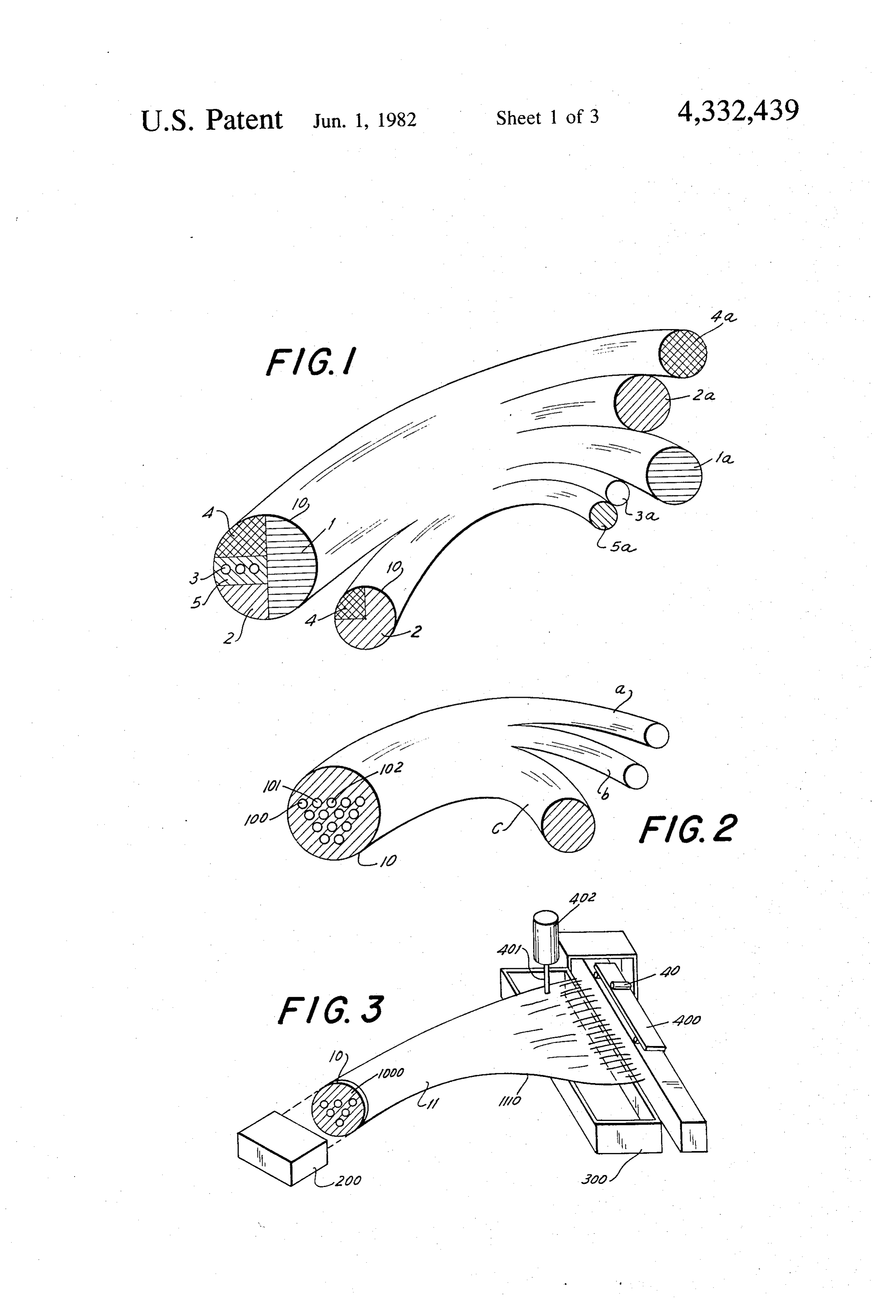
In an arrangement in which the other end of the light EMBODIMENTS conductor has a relatively large end face the illuminat Referring now to the drawing and more specifically ing device may be constituted by the screen of a cath 5 to FIG. 1 of the same in which a light conductor ac ode ray tube in which the light points on the screen may cording to the present invention is schematically illus be electronically controlled in a known manner. trated, it will be seen that this light conductor is divided An especially- simple arrangement according to the at its one end, shown in the drawing as the right end, method of the present invention is derived when the intowhereas a plurality of individual strands 1a, 2a, 3a, 4a and illuminating device comprises an array of individual 10 5a, is divided the other end face 10 of the light conductor in a plurality of specific, but randomly ar light sources. ranged regions 1, 2, 3, 4 and 5, as indicated by the differ Since the light conductor according to the present ent invention usually consists of a great number of individ the cross-hatching strands at the of these regions and in which each of one end is coordinated with a specific ual fibers, it is important that the separation of the fibers 15 region of the other end. Due to this arrangement it is is automatically performed. possible to connect the sections or partial end faces 1-5 The separation of the fibers into light carrying fibers with different optical elements, as for instance receivers and non-light carrying fibers may comprise the step of or emitters, whereby the geometrical shape of the sur automatically displacing the light carrying fibers and face portions 1-5 is adapted to the geometrical form of the non-light carrying fibers with respect to each other these optical elements, whereas the shape of the end and such displacement may be carried out by a photo faces 1a-5a is determined by corresponding forming electronic controlled punch or by photoelectronic con and subsequent connecting, for instance by cementing trolled gas impulses in which the gas impulse may be a the fibers forming the strands so as to be adapted to be suction or a pressure impulse. Another method of sepa connected to other optical elements.
rating the light carrying fibers from the non-light carry 25 FIG. 2 schematically illustrates another embodiment ing fibers comprises the steps of securing all fibers at the of a light conductor according to the present invention one end by a lightsensitive lacquer to a support, illumi in which the end face 10 is provided with two different nating the lacquer by the light carrying fibers and re elementary areas in which the small areas 100, 101, 102, leasing the light carrying fibers from the support by etc., are spatially periodically distributed. The fibers of etching. In this way a subsequent hand-sorting of the the elementary areas 100, 101, 102, etc. are gathered fibers is greatly simplified. together in two strands a and b, whereas the other fi The novel features which are considered as charac bers, that is those which surround the aforementioned teristic for the invention are set forth in particular in the tional strandareas elementary are connected together in an addi c. The arrangement constitutes therefore appended claims. The invention itself, however, both as 35 for the elementary areas 100, 101, 102, etc. a light ray to its construction and its method of operation, together divider, whereby the divider relationship between the with additional objects and advantages thereof, will be two strands a and b is determined by the number of best understood from the following description of spe respective connected fibers and this arrangement may cific embodiments when read in connection with the for instance be used in order to direct light over the accompanying drawing. strands a and b to a receiver which light has been di BRIEF DESCRIPTION OF THE DRAWING rected over the strand c to a reflecting object. Object, receiver and light source are not shown in FIG. 2.
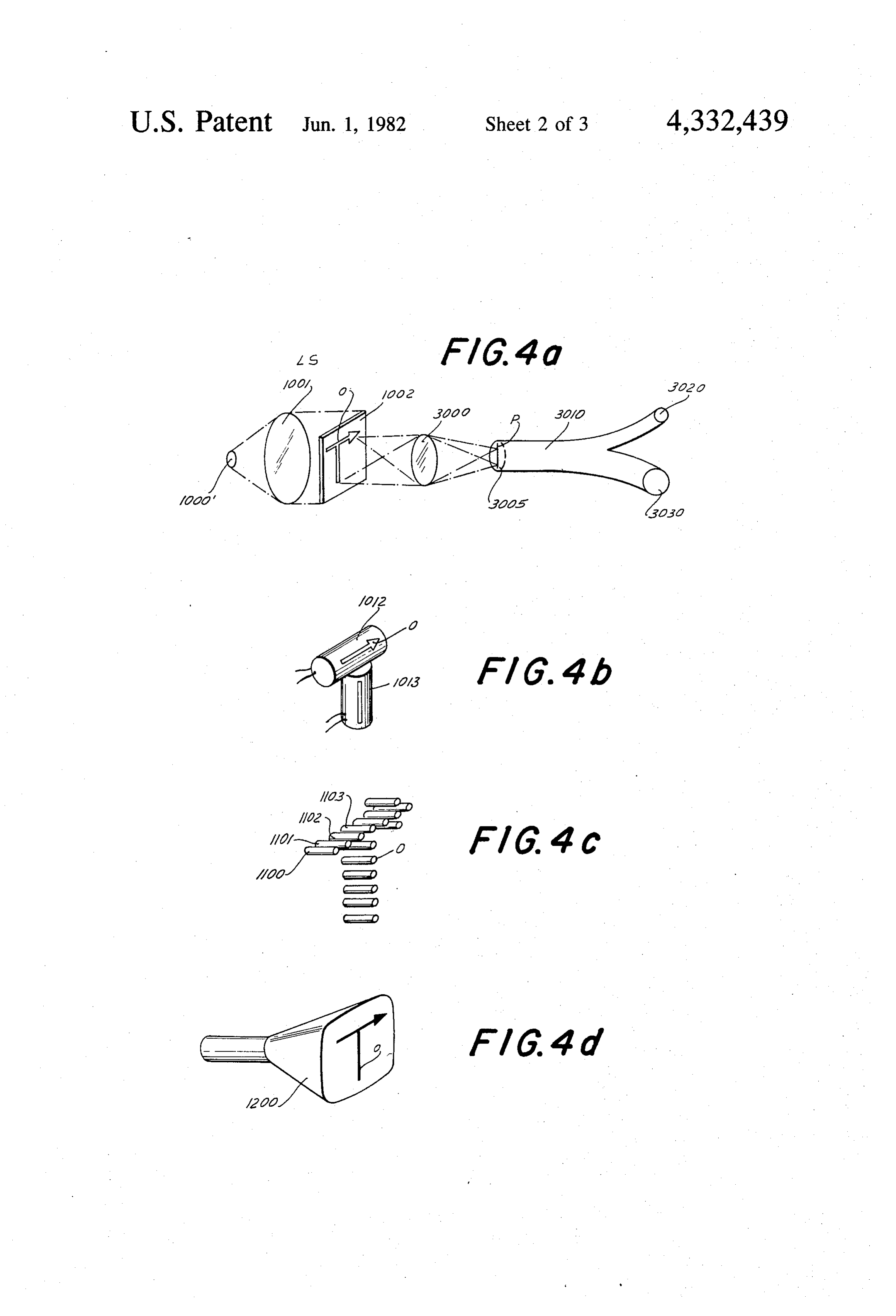
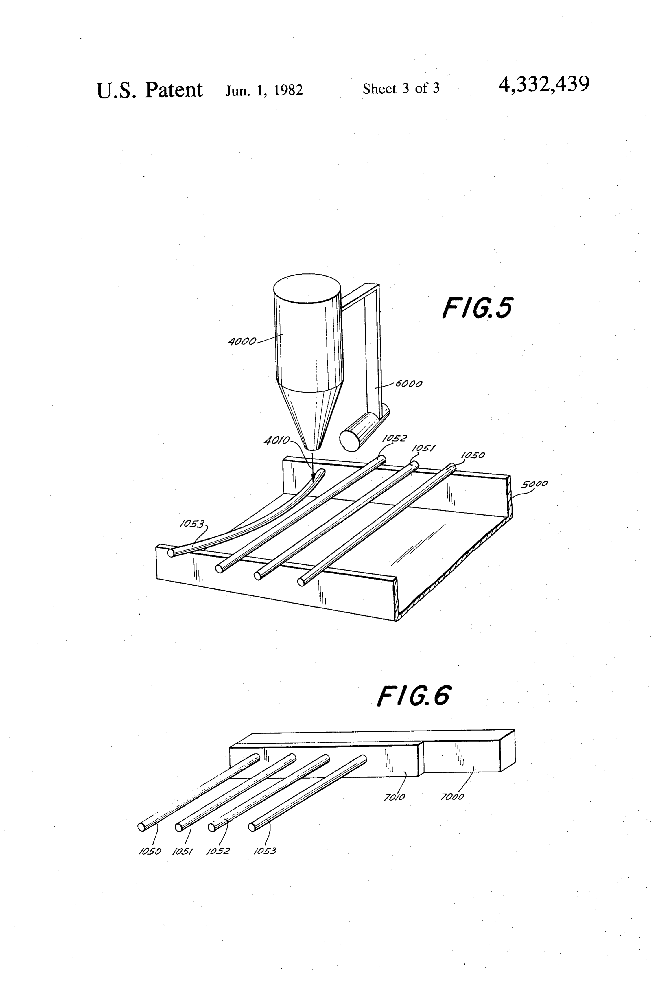
FIG. 1 schematically illustrates a light conductor FIG. 3 schematically illustrates apparatus for manu according to the present invention in which separate facturing the light conductor shown in FIG. 2. As strands at one end of the light conductor are coordi 45 shown in FIG.3 a mask 1000 is placed on the end 10 of nated with a specific but randomly arranged regions of the light conductor 11 which faces a light source 200. the other end of the light conductor; This mask 1000, which may be produced by a known FIG. 2 schematically illustrates a light conductor photochemical process, is transparent at the areas corre according to the present invention wherein the other 50 sponding to the elementary areas 100, 101, 102, etc. end of the light conductor is subdivided into a plurality shown in FIG. 2, whereas the surrounding areas of the of different elementary areas and wherein each strand shown mask are opaque. The fibers 1,110 at the right end, as of the one end is coordinated with a specific area of the are spread in FIG. 3, are not yet connected together, but other end; in a row and abut with the ends thereof on a FIG. 3 schematically illustrates a method for produc 55 the frame 300. A carriage 400 is movable longitudinally of ing a light conductor according to the present inven cal direction frame 300 and carries a punch 401 movable in verti tion; and operated by a magnet 402. The magnet FIGS. 4a-4d illustrate respectively methods accord 400 in a planebycoinciding is controlled a photocell 40 carried by the carriage with the plane at which the ing to the present invention for producing at the other unconnected ends of the fibers are arranged and facing end of the light conductor an illuminated area of a spe the latter. If the mask 1000 is now illuminated by the cific pattern; light source 200, then only those fibers will carry light FIG. 5 schematically illustrates a method according which are arranged behind the transparent surface por to the present invention in which light carrying fibers tions of the mask 1000. The plunger 401 which is con are separated from non-light carrying fibers by gas trolled by the photocell 40 will move downwardly impulses; and 65 whenever light through a light carrying fiber impinges FIG. 6 schematically illustrates a further method on the photocell 40 to thereby displace the light carry according to the present invention for separating light ing fiber downwardly into the trough-shaped frame carrying fibers from non-light carrying fibers. 300, so that in this way the light carrying fibers which
Page 7
are located behind the transparent surface portions of then be connected to a strand 3020 whereas the non the mask 1000 are separated from the other fibers, light carrying fibers may be connected to an additional Instead of a mechanically operated punch or plunger strand 3030.
it is also possible to use suction or pressure gas impulses FIG. 4b illustrates another embodiment in which the produced by an air stream to separate the light carrying illuminating arrangement LS including the light source fibers from the non-light carrying fibers. Such an ar 1000", the lens 1001 and the mask 1002 with the slit O rangement is schematically illustrated in FIG. 5, therein is replaced by two light sources respectively wherein the disconnected ends 1050, 1051, 1052 and arranged in cylindrical casings 1012 and 1013 arranged 1053, etc. are again located on the side walls of a with respect to each other as shown in FIG. 4b and trough-shaped frame 5000. A fine nozzle 4000 supplied O formed with respective slits O so that substantially the with air under pressure emits, when opened, a down same image or illuminated pattern as is produced by the wardly directed narrow air stream 4010 and opening arrangement shown in FIG. 4a will be produced on the and closing of the nozzle is controlled, in a manner end face 3005 of the light conductor not shown in FIG. known perse and not forming part of the present inven 4b.
tion, by a photocell 6000 connected to the nozzle 4000 15 A further embodiment is schematically illustrated in for movement therewith along a path parallel to the FIG. 4c in which the illuminating arrangement includes frame 5000 in the manner as described in connection a plurality of individual light sources 1100, 1101, 1102, with FIG. 3. If, for instance, the fiber 1053 is arranged 1103, etc. arranged in a specific array to produce for behind a transparent portion of the mask in FIG. 5 such instance on the end face 3005, not shown in FIG. 4c an light will impinge on the photocell 6000 to open the 20 illuminated area in the form of a T permitting thereby nozzle so that the air stream 400 emanating therefron again to separate the fibers into light carrying fibers and will displace the right end, as viewed in FIG. 5, of the non-light carrying fibers by means of any of the meth fiber 1053 in downward direction. If any of the follow ods illustrated in FIGS. 3, 5 and 6. ing fibers is located behind an opaque portion of the Finally, FIG. 4d illustrates an illuminating arrange mask, the photocell 6000 will not be actuated and the 25 ment in form of a cathode ray tube on the screen of right end of this fiber will remain on the side wall of the which an image O is produced by controlling the ray of trough-shaped frame 5000. In this way the fibers are the cathode tube, in a manner known per se, which again separated in light carrying and non-light carrying again permits to separate the light carrying fibers from fibers which may then be respectively connected to the non-light carrying fibers in the manner as discussed each other to form the strands a, b and c as shown in 30 before.
FIG. 2, While the various arrangements shown in FIGS. Another way of separating the light carrying from 4a–4a are made to produce a substantially T-shaped the non-light carrying fibers is schematically illustrated image on the end 3005 of the light conductor, it is evi in FIG. 6. As shown therein the plurality of uncon dent that any other illuminated pattern may be pro nected fibers 1050, 1051, 1052, 1053, etc. are connected 35 duced thereon.
by a layer 7010 of a photosensitive lacquer on a support It is further mentioned that the light emanating from 7000 of transparent material. The connected left ends of the light sources 1012 and 1013 shown in FIG. 4b or the the fibers, not shown in FIG. 6 are located, for instance, individual light sources 1100, etc. as shown in FIG. 4c behind a mask 1000 as described in connection with may be all of the same color or of different colors which FIG. 3 and are exposed to the light emanating from a 40 would permit to separate the light carrying fibers, not light source, not shown in FIG. 6, so that some of the automatically, but by hand into two different strands, as fibers will be light carrying fibers and the other will be for instance shown in FIG. 2.
non-light carrying fibers. After a short exposure to the It will be understood that each of the elements de light, the arrangement as shown in FIG. 6 is emerged scribed above, or two or more together, may also find a into an etching solution. Thereby the layer 7010 is 45 useful application in other types of light conductors and etched away around those fibers which have been light methods of making the same differing from the types carrying fibers and these fibers are thus freed and may described above.
be separated from the others. While the invention has been illustrated and de While FIG. 3 illustrated a mask 1000 with transparent scribed as embodied in a light conductor and methods and opaque portions connected to the left end of a light 50 of making the same, it is not intended to be limited to the conductor according to the present invention, it is also details shown, since various modifications and struc possible to produce a mask or an equivalent thereof, tural changes may be made without departing in any that is an illuminated pattern, by optical means. Various way from the spirit of the present invention. modifications of such an arrangement are illustrated in Without further analysis, the foregoing will so fully FIGS. 4a-4d. As shown in FIG. 4a an illuminated ar 55 reveal the gist of the present invention that others can, rangement LS including a substantially point-shaped by applying current knowledge, readily adapt it for light source 1000 and a lens 1001 transforming the light various applications without omitting features that, rays emanating from the light source 1000' into parallel from the standpoint of prior art, fairly constitute essen light rays is arranged to one side of a mask 1002 pro tial characteristics of the generic or specific aspects of vided with an opening or slits O of any desired outline this invention.
so that the light rays will pass only through this opening What is claimed as new and desired to be protected O through an additional lens 3000, whereby a lightened by Letters Patent is set forth in the appended claims: area or pattern P corresponding to the opening or the 1. A method for the production of a light conductor slits O in the mask 1002 is produced on the end face having opposite ends and composed of a plurality of 3005 of the light conductor 3010, so that the light carry 65 thin fibers, wherein at least one of said ends is divided ing fibers may be separated from the non-light carrying into a plurality of strands and wherein each strand of fibers by any of the methods discussed above in connec said one end comprises fibers of a specific one of a tion with FIGS. 3, 5 and 6 and the light carrying fibers plurality of regions at the other end arranged in any
Page 8
desired pattern, said method comprising the steps of connecting said light carrying fibers, respectively said producing at said other end an illuminated pattern of non-light carrying fibers into said separate strands. any desired outline so that some of the fibers will be 3. A method for the production of a light conductor light carrying fibers and the other non-light carrying having opposite ends and composed of a plurality of fibers; displacing said light carrying fibers and said non 5 thin fibers, wherein at least one of said ends is divided in light carrying fibers with respect to each other by a a plurality of strands and wherein each strand of said photoelectric control rod punch; and connecting said one end comprises fibers of a specific one of a plurality light carrying fibers, respectively said non-light carry of regions at the other end arranged in any desired ing fibers into said separate strands. pattern, said method comprising the steps of producing 2. A method for the production of a light conductor O at said other end an illuminated pattern of any desired having opposite ends and composed of a plurality of thin fibers, wherein at least one of said ends is divided in outline so that some of said fibers will be light carrying a plurality of strands, and wherein each strand of said fibers and the other non-light carrying fibers; separating one end comprises fibers of a specific one of a plurality said light carrying fibers from said non-light carrying of regions at the other end arranged in any desired 15 fibers by securing all fibers at said one end in a row by pattern, said method comprising the steps of producing a light sensitive lacquer to a support, illuminating the at said other end in illuminated pattern of any desired lacquer by said light carrying fibers and releasing said outline so that some of said fibers will be light carrying light carrying fibers from said support by etching; and fibers and the other non-light carrying fibers; displacing connecting said light carrying fibers, respectively said said light carrying fibers and said non-light carrying 20 non-light carrying fibers into said separate strands. fibers with respect to each other by gas impulses; and k.
Provenance
- Collection
- Cited prior art
- Original PDF
- patentimages.storage.googleapis.com →
- Filed
- 1979-07-26
- Pages
- 8
- Method
- pdftotext (the PDF's own text layer) + pdftoppm 300dpi page scans
- Source
- Google Patents bibliographic record
- Granted
- 1982-06-01
- Inventors
- Dietrich W. Lubbers; Friedbert Hannebauer; Max Planck Gesellschaft zur Foerderung der Wissenschaften eV
- Transcribed from
- patentimages.storage.googleapis.com →