patent · US3556085
Optical viewing instrument
19 January 1971
Page 1 — bibliographic record
United States Patent (11) 3,556,085 72 Inventor Nagashige Takahashi Primary Examiner-Richard A. Gaudet Tokyo, Japan Assistant Examiner-J. B. Mitchell (21) Appl. No. 708,242 Attorney-Kurt Kelman
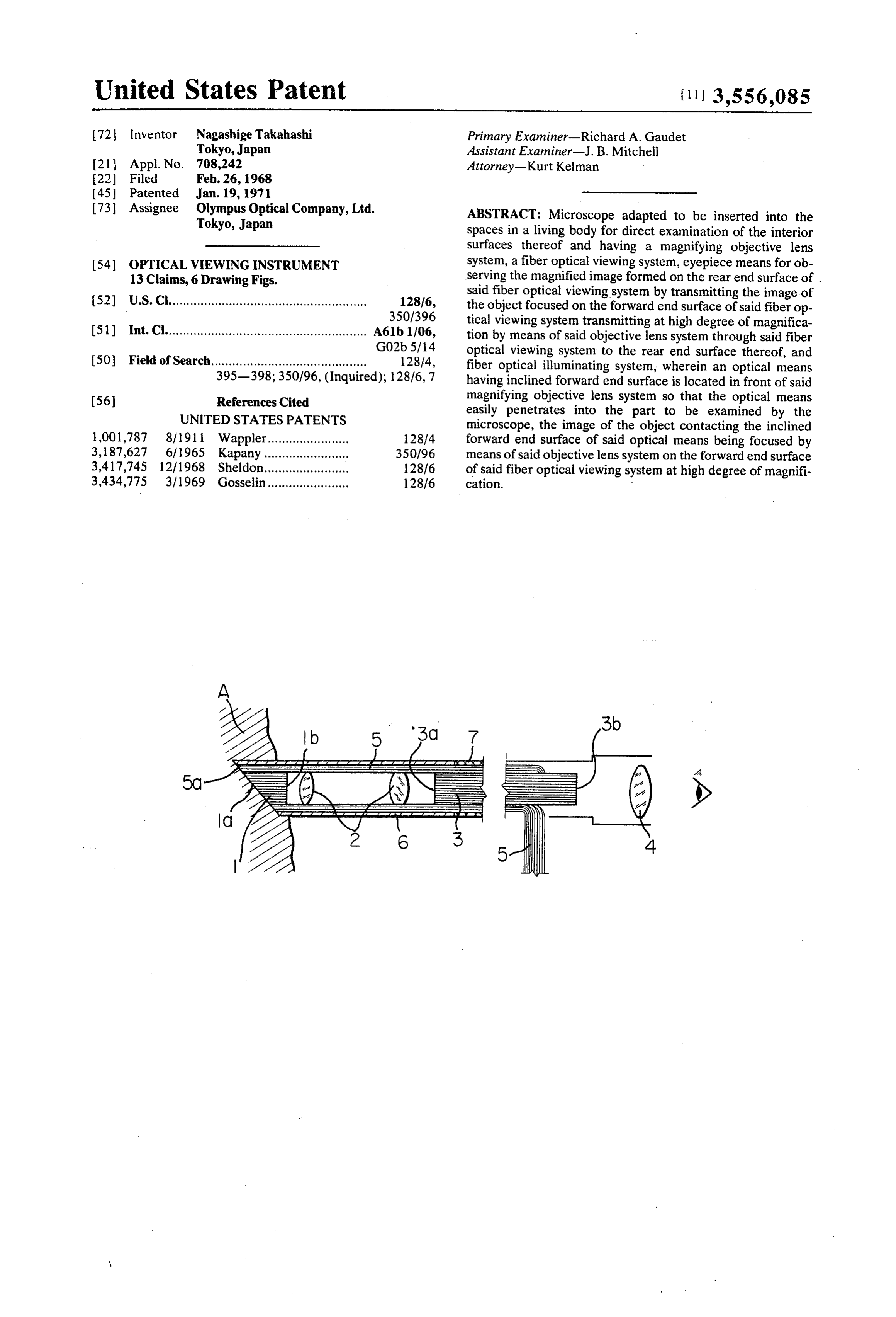
73 Assignee Olympus Optical Company, Ltd. ABSTRACT: Microscope adapted to be inserted into the Tokyo, Japan spaces in a living body for direct examination of the interior surfaces thereof and having a magnifying objective lens (54) OPTICAL VIEWING INSTRUMENT system, a fiber optical viewing system, eyepiece means for ob 13 Claims, 6 Drawing Figs. serving the magnified image formed on the rear end surface of . said fiber optical viewing system by transmitting the image of 52 U.S. Cl........................................................ 128/6, the object focused on the forward end surface of said fiber op 350/396 tical viewing system transmitting at high degree of magnifica (51 int. Cl......................................................... A61b1/06, tion by means of said objective lens system through said fiber G02b 5/14 optical viewing system to the rear end surface thereof, and (50 Field of Search............................................ 128/4, fiber optical illuminating system, wherein an optical means 395-398; 350/96, (Inquired); 12876, 7 having inclined forward end surface is located in front of said (56) References Cited magnifying objective lens system so that the optical means
UNITED STATES PATENTS
easily penetrates into the part to be examined by the microscope, the image of the object contacting the inclined 1,001,787 8/1911 Wappler. 128/4 forward end surface of said optical means being focused by 3,187,627 6/1965 Kapany.... 350/96 means of said objective lens system on the forward end surface 3,417,745 12/1968 Sheldon.... 128/6 of said fiber optical viewing system at high degree of magnifi 3,434,775 3/1969 Gosselin....................... 128/6 cation.
Page 2
Drawing sheet — no readable text.
Page 3
Drawing sheet — no readable text.
Page 4
OPTICAL VIEWING INSTRUMENT advantage of the prior art previously mentioned and which in corporates a removable microscope having a magnifying opti
Optical viewing instrument adapted to be inserted into the cal system. The end surface of said viewing instrument is in spaces in a living body for direct examination of the interior Sertable together with said microscope incorporated therein surfaces thereof and comprising objective lens system, fiber into the internal orgah of the living body where the diagnostic optical viewing system, eyepiece means, and fiber optical illu examination is to be carried out. The end surface of said opti minating system, wherein a microscope is detachably inserted cal system penetrates that part of the internal organ to be ex through a guide hole provided in said optical viewing instru amined so that examination under high magnification can be ment so that the tip of the microscope projects from the for directly carried out without the necessity of excising a ward end of the optical viewing instrument, said microscope O specimen from the internal organ for examination with a con comprising optical means having the inclined forward end sur ventional microscope. Further, if desired, the microscope can face, magnifying objective lens system, fiber optical viewing be removed from said viewing instrument and specimen system, and eyepiece means, said optical means easily gathering means such as forceps can be inserted in place of penetrating into the part to be examined by the microscope said microscope for picking specimens out of the internal or after that part to be examined has been found out by using the 15 gan.
optical system of said optical viewing instrument. One feature of the present invention is a microscope which comprises a fiber optical system of very small diameter. The
BACKGROUND OF THE INVENTION tip of said microscope fiber optical system is inclined with Heretofore, diagnostic inspection or observation of the tis cal respect to the plane normal to the optical axis of the fiber opti sue or the cells of the living body has been carried out by ex tivesystem so that it forms a sharp point. A magnifying objec lens system is located behind said fiber optical system in cising a specimen from the internal organ of the living body for examination with a microscope of the conventional type. optical alignment therewith at an appropriate distance from However, such a procedure is very time consuming and the rear end surface thereof, and a fiber optical viewing troublesome. Further, doctors, pathologists, scientists, and 25 system
is located behind said magnifying objective lens system optical alignment therewith with the front end surface of others have long desired to inspect or observe tissue or cells in said fiber optical viewing system being an appropriate distance the internal organ of the living body directly, without the necessity of excising a specimen from the portion to be in from said magnifying objective lens system. An eyepiece spected and thereby to discover diseases such as ulcer or means is located behind the rear end surface of said fiber opti cal viewing system in optical alignment therewith, and a fiber cancer at an earlier stage so countermeasures will be more ef 30 optical fective. illuminating system extends along said first mentioned The present invention, therefore, relates to a microscope fiber optical system, magnifying objective lens system and the with which it is possible to examine directly the interior sur entirety or a portion of said fiber optical viewing system for face of spaces within a living body, such as human body, not transmitting light from a light source connected thereto open to direct examination by sight or touch. More particu 35 through the fiber optical illuminating system to the tip thereof larly, the present invention is directed to a microscope which so that the object to be inspected is illuminated. A pipe sur is most advantageously used in the examination of internal or rounds said first mentioned fiber optical system, said magnify gans such as the bronchia of the human body and for direct ex ing objective lens system, the front end portion of said fiber amination under high magnification of cells or tissue in the in 40 optical viewing system and the portion of said fiber optical il ternal organ damaged by disease (ulcer, cancer, etc.). With luminating system extending along the above mentioned ele the present invention, the end surface of the objective lens ments so that the tip of said first mentioned fiber optical system of the microscope is inserted into that part of the in system can be properly inserted into that part of the internal terior surface in the living body where there is suspicion of dis organ to be directly inspected when the microscope is used; ease, and there is no need to excise a specimen from the inter 45 the remaining portions of the above mentioned elements are nal organ for microscopic examination. covered by a rigid or flexible sheath for protection of the ele The present invention further relates to an optical viewing ments to be inserted into the internal organ, the image of the instrument for direct examination of interior surface of spaces object contacting the tip of said first mentioned fiber optical within a living body in which a microscope having a fiber opti system being transmitted therethrough to the rear end surface cal system adapted to penetrate directly into the internal thereof, the image on the rear end surface of the first men organ of the living body is detachably assembled in the optical 50 tioned fiber optical system being focused by said magnifying viewing instrument thereby permitting diagnostic examination objective lens system onto the front end surface of said fiber under high magnification of said internal organ to be carried optical viewing system at a high degree of magnification so out directly without the excision of cells or tissue from the liv that the magnified image thus focused on the front end surface ing body. In use, the procedure is to make a general survey of 55 of the fiber optical viewing system is transmitted therethrough the internal organ by inserting the optical viewing instrument to the rear end surface of the fiber optical viewing system. The and examining by means of the objective lens system and fiber image transmitted to the rear end surface of the fiber optical optical viewing system incorporated in the optical viewing in viewing system is further magnified by the eyepiece means for strument; then the microscope with fiber optical system is observation of the image of the object at a high degree of mag used for examination under a high degree of magnification. 60 nification.
Also, if desired, specimen gathering means such as forceps Another feature of the present invention is that the above and the like can be used in place of the microscope by remov. mentioned fiber optical system coming to a point may be ing the microscope from the optical viewing instrument and replaced by a parallel plane optical element which is located replacing with the specimen gathering means. in inclined relationship with respect to the plane normal to the 65 optical axis of the magnifying objective lens system so that
SUMMARY OF THE INVENTION part of the edge can easily penetrate the internal organ to be One object of the present invention is, therefore, to provide examined. The front end surface of the fiber optical viewing a novel and useful microscope which does not require excising system is inclined with respect to the plane normal to the opti a specimen as is necessary with the prior art microscope and cal axis of the magnifying objective lens system so that said with which diagnostic examination of the internal organ of the 70 parallel plane optical element and the front end surface of the living body can be directly carried out by inserting the forward fiber optical viewing system are in optically conjugate rela end surface of the microscope into the internal organ of the tionship with each other thereby permitting the sharp image of living body. the object to be focused on the front end surface of the fiber Another object of the present invention is to provide a novel 75 optical viewing system although evenness of the magnification and useful optical viewing instrument which can avoid the dis of the image is impaired to some extent. Alternatively, the
Page 5
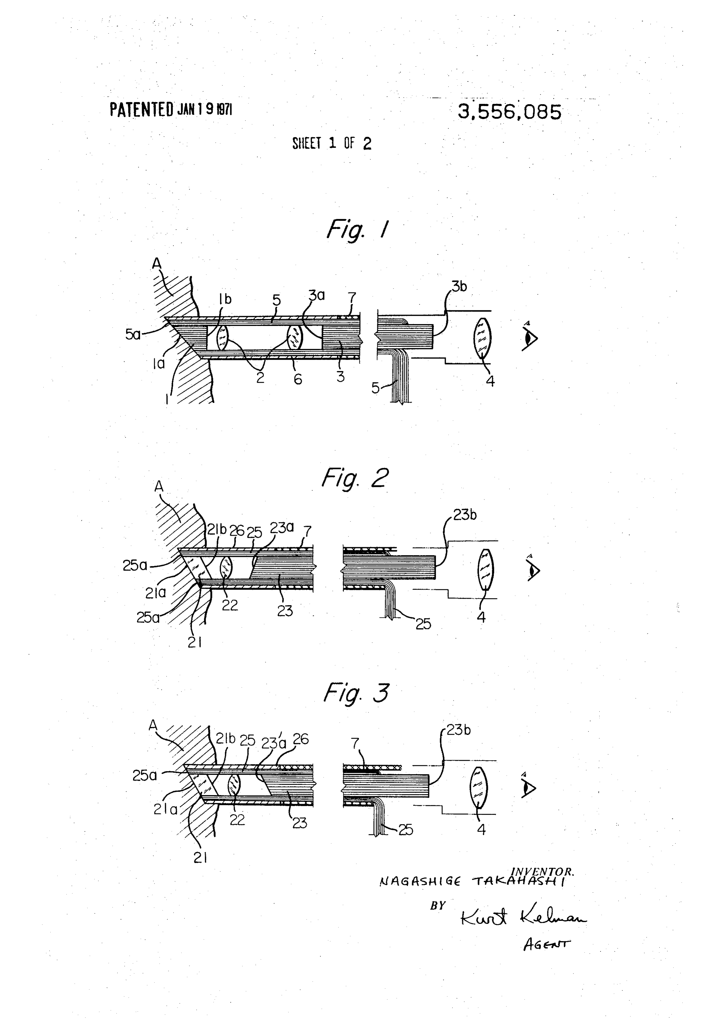
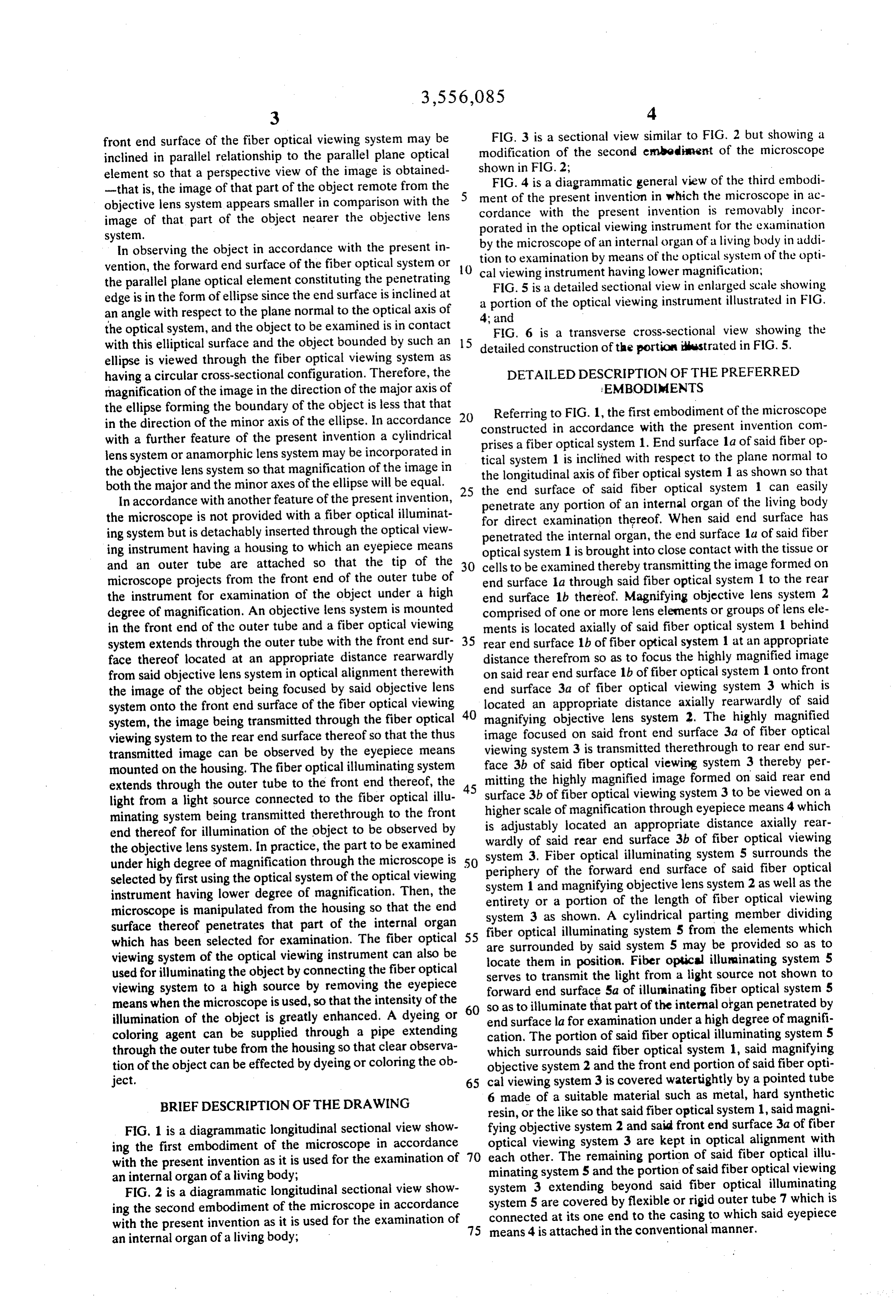
front end surface of the fiber optical viewing system may be FIG. 3 is a sectional view similar to FIG. 2 but showing a inclined in parallel relationship to the parallel plane optical modification of the second embodinent of the microscope element so that a perspective view of the image is obtained shown in FIG. 2;
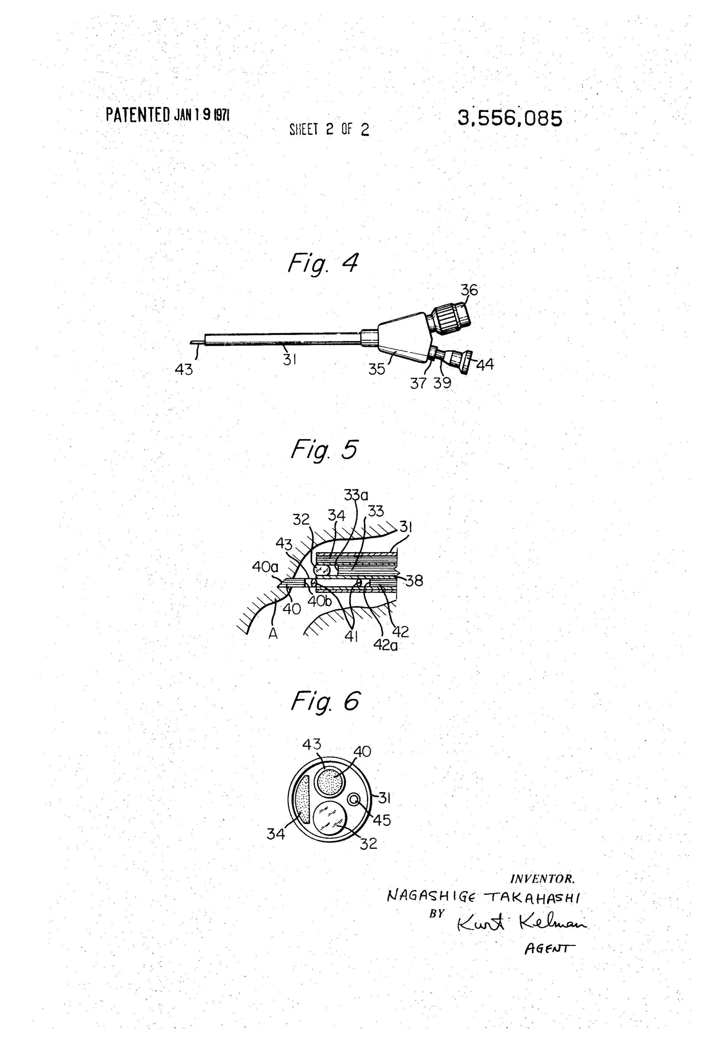
-that is, the image of that part of the object remote from the FIG. 4 is a diagrammatic general view of the third embodi objective lens system appears smaller in comparison with the ment of the present invention in which the microscope in ac image of that part of the object nearer the objective lens cordance with the present invention is removably incor
porated in the optical viewing instrument for the examination
In observing the object in accordance with the present in by the microscope of an internal organ of a living body in addi vention, the forward end surface of the fiber optical system or tion to examination by means of the optical system of the opti O cal viewing instrument having lower magnification;
the parallel plane optical element constituting the penetrating FIG. 5 is a detailed sectional view in enlarged scale showing edge is in the form of ellipse since the end surface is inclined at a portion of the optical viewing instrument illustrated in FIG. an angle with respect to the plane normal to the optical axis of the optical system, and the object to be examined is in contact 4; and FIG. 6 is a transverse cross-sectional view showing the with this elliptical surface and the object bounded by such an 15 detailed construction of the portion illustrated in FIG. 5. ellipse is viewed through the fiber optical viewing system as having a circular cross-sectional configuration. Therefore, the DETAILED DESCRIPTION OF THE PREFERRED magnification of the image in the direction of the major axis of EMBODIENTS the ellipse forming the boundary of the object is less that that Referring to FIG. 1, the first embodiment of the microscope in the direction of the minor axis of the ellipse. In accordance constructed in accordance with the present invention com with a further feature of the present invention a cylindrical prises a fiber optical system 1. End surface 1a of said fiber op lens system or anamorphic lens system may be incorporated in the objective lens system so that magnification of the image in tical system 1 is inclined with respect to the plane normal to the longitudinal axis of fiber optical system 1 as shown so that both the major and the minor axes of the ellipse will be equal. 25 the end surface of said fiber optical system 1 can easily In accordance with another feature of the present invention, penetrate any portion of an internal organ of the living body the microscope is not provided with a fiber optical illuminat for direct examination thereof. When said end surface has ing system but is detachably inserted through the optical view penetrated the internal organ, the end surface 1a of said fiber ing instrument having a housing to which an eyepiece means optical system 1 is brought into close contact with the tissue or and an outer tube are attached so that the tip of the 30 cells to be examined thereby transmitting the image formed on microscope projects from the front end of the outer tube of end surface la through said fiber optical system 1 to the rear the instrument for examination of the object under a high end surface 1b thereof. Magnifying objective lens system 2 degree of magnification. An objective lens system is mounted comprised of one or more lens elements or groups of lens ele in the front end of the outer tube and a fiber optical viewing ments is located axially of said fiber optical system 1 behind system extends through the outer tube with the front end sur 35 rear end surface 1b of fiber optical system 1 at an appropriate face thereof located at an appropriate distance rearwardly distance therefrom so as to focus the highly magnified image from said objective lens system in optical alignment therewith on said rear end surface 1b of fiber optical system 1 onto front the image of the object being focused by said objective lens end surface 3a of fiber optical viewing system 3 which is system onto the front end surface of the fiber optical viewing located an appropriate distance axially rearwardly of said system, the image being transmitted through the fiber optical 40 magnifying objective lens system 2. The highly magnified viewing system to the rear end surface thereof so that the thus image focused on said front end surface 3a of fiber optical transmitted image can be observed by the eyepiece means face viewing system 3 is transmitted therethrough to rear end sur mounted on the housing. The fiber optical illuminating system 3b of said fiber optical viewing system 3 thereby per extends through the outer tube to the front end thereof, the 45 mitting the highly magnified image formed on said rear end light from a light source connected to the fiber optical illu higher scaleofoffiber surface 3b optical viewing system 3 to be viewed on a magnification through eyepiece means 4 which minating system being transmitted therethrough to the front is adjustably located end thereof for illumination of the object to be observed by wardly of said rear endan surface appropriate distance axially rear 3b of fiber optical viewing the objective lens system. In practice, the part to be examined system 3. Fiber optical illuminating under high degree of magnification through the microscope is 50 periphery of the forward end surfacesystem 5 surrounds the selected by first using the optical system of the optical viewing system 1 and magnifying objective lens system 2 asfiber of said optical instrument having lower degree of magnification. Then, the entirety or a portion of the length of fiber opticalwellviewing as the microscope is manipulated from the housing so that the end system 3 as shown. A cylindrical parting member dividing surface thereof penetrates that part of the internal organ fiber optical illuminating system 5 from the elements which
which has been selected for examination. The fiber optical are surrounded by said system 5 may be provided so as to viewing system of the optical viewing instrument can also be locate them in position. Fiber optical illuminating system 5 used for illuminating the object by connecting the fiber optical serves to transmit the light from a light source not shown to viewing system to a high source by removing the eyepiece forward end surface 5a of illuminating fiber optical system 5 means when the microscope is used, so that the intensity of the 60 so as to illuminate that part of the internal organ penetrated by illumination of the object is greatly enhanced. A dyeing or end surface la for examination under a high degree of magnifi coloring agent can be supplied through a pipe extending cation. The portion of said fiber optical illuminating system 5 through the outer tube from the housing so that clear observa which surrounds said fiber optical system 1, said magnifying tion of the object can be effected by dyeing or coloring the ob objective system 2 and the front end portion of said fiber opti ject. 65 cal viewing system 3 is covered watertightly by a pointed tube BRIEF DESCRIPTION OF THE DRAWING 6 made of a suitable material such as metal, hard synthetic resin, or the like so that said fiber optical system 1, said magni
FIG. 1 is a diagrammatic longitudinal sectional view show fying objective system 2 and said front end surface 3a of fiber ing the first embodiment of the microscope in accordance 70 optical viewing system 3 are kept in optical alignment with with the present invention as it is used for the examination of each other. The remaining portion of said fiber optical illu minating system 5 and the portion of said fiber optical viewing an internal organ of a living body;
FIG. 2 is a diagrammatic longitudinal sectional view show system 3 extending beyond said fiber optical illuminating ing the second embodiment of the microscope in accordance system 5 are covered by flexible or rigid outer tube 7 which is with the present invention as it is used for the examination of 75 connected means 4 is at its one end to the casing to which said eyepiece attached in the conventional manner.
an internal organ of a living body;
Page 6
S 6
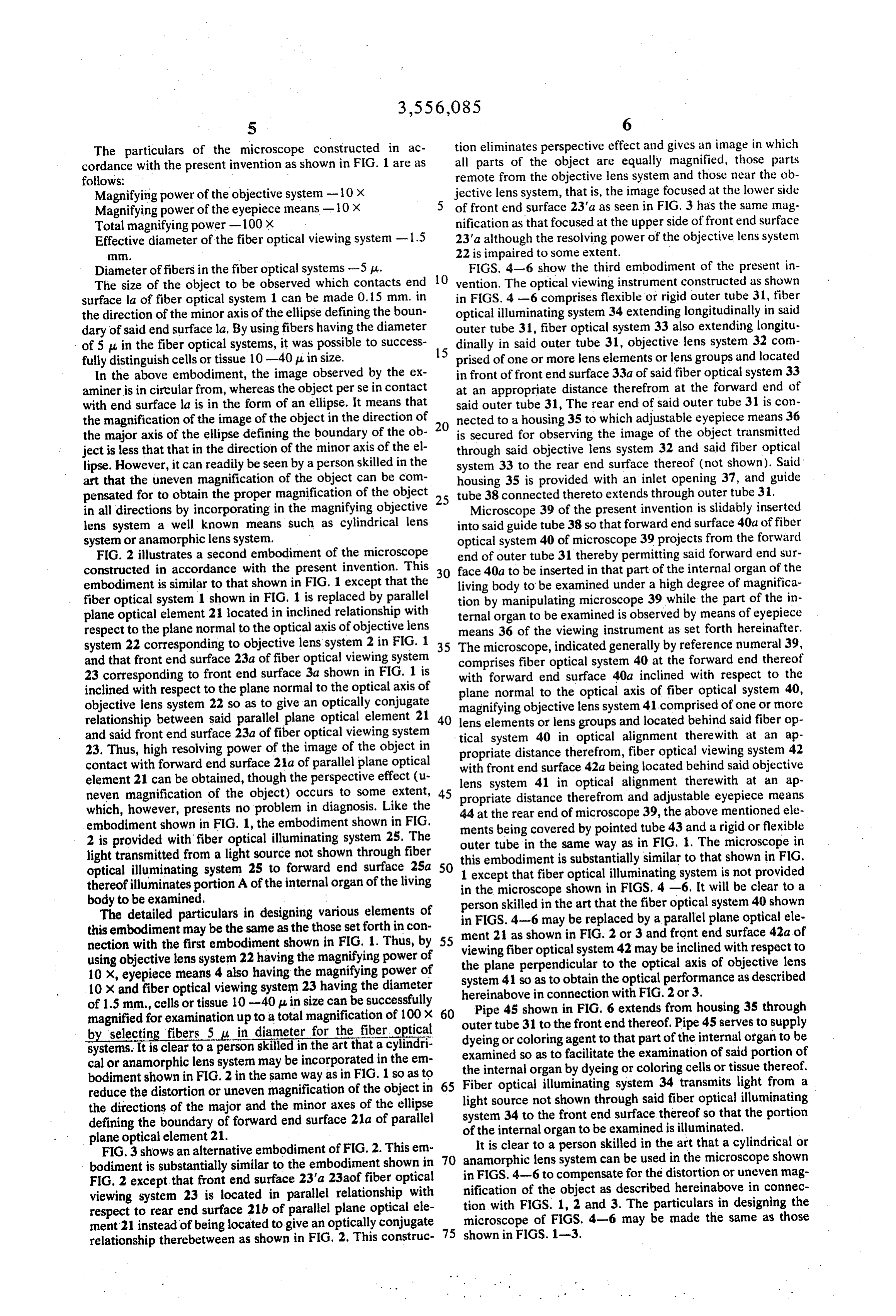
The particulars of the microscope constructed in ac tion eliminates perspective effect and gives an image in which all parts of the object are equally magnified, those parts cordance with the present invention as shown in FIG. 1 are as follows: remote from the objective lens system and those near the ob Magnifying power of the objective system-10 x jective lens system, that is, the image focused at the lower side Magnifying power of the eyepiece means - 10 x of front end surface 23'a as seen in FIG. 3 has the same mag Total magnifying power -100X nification as that focused at the upper side of front end surface Effective diameter of the fiber optical viewing system - 1.5 23'a although the resolving power of the objective lens system . 22 is impaired to some extent.
Diameter of fibers in the fiber optical systems -5 u. FIGS. 4-6 show the third embodiment of the present in The size of the object to be observed which contacts end 10 vention. The optical viewing instrument constructed as shown surface la of fiber optical system 1 can be made 0.15 mm. in in FIGS. 4 -6 comprises flexible or rigid outer tube 31, fiber the direction of the minor axis of the ellipse defining the boun optical illuminating system 34 extending longitudinally in said dary of said end surface la. By using fibers having the diameter outer tube 31, fiber optical system 33 also extending longitu of 5 . . in the fiber optical systems, it was possible to success 15 dinally in said outer tube 31, objective lens system 32 com fully distinguish cells or tissue 10-40 u in size. prised of one or more lens elements or lens groups and located In the above embodiment, the image observed by the ex in front of front end surface 33a of said fiber optical system 33 aminer is in circular from, whereas the object perse in contact at an appropriate distance therefrom at the forward end of with end surface la is in the form of an ellipse. It means that said outer tube 31, The rear end of said outer tube 31 is con the magnification of the image of the object in the direction of nected to a housing 35 to which adjustable eyepiece means 36 the major axis of the ellipse defining the boundary of the ob is secured for observing the image of the object transmitted ject is less that that in the direction of the minor axis of the el through said objective lens system 32 and said fiber optical lipse. However, it can readily be seen by a person skilled in the system 33 to the rear end surface thereof (not shown). Said art that the uneven magnification of the object can be com housing 35 is provided with an inlet opening 37, and guide pensated for to obtain the proper magnification of the object 25 tube 38 connected thereto extends through outer tube 31. in all directions by incorporating in the magnifying objective Microscope 39 of the present invention is slidably inserted lens system a well known means such as cylindrical lens into said guide tube 38 so that forward end surface 4.0a of fiber system or anamorphic lens system. optical system 40 of microscope 39 projects from the forward FIG. 2 illustrates a second embodiment of the microscope end of outer tube 31 thereby permitting said forward end sur constructed in accordance with the present invention. This 30 face 4.0a to be inserted in that part of the internal organ of the embodiment is similar to that shown in FIG. 1 except that the living body to be examined under a high degree of magnifica fiber optical system 1 shown in FIG. 1 is replaced by parallel tion by manipulating microscope 39 while the part of the in plane optical element 21 located in inclined relationship with ternal organ to be examined is observed by means of eyepiece respect to the plane normal to the optical axis of objective lens means 36 of the viewing instrument as set forth hereinafter. system 22 corresponding to objective lens system 2 in FIG. 1 35 The microscope, indicated generally by reference numeral 39, and that front end surface 23a of fiber optical viewing system comprises fiber optical system 40 at the forward end thereof 23 corresponding to front end surface 3a shown in FIG. 1 is with forward end surface 4.0a inclined with respect to the inclined with respect to the plane normal to the optical axis of plane normal to the optical axis of fiber optical system 40, objective lens system 22 so as to give an optically conjugate magnifying objective lens system 41 comprised of one or more relationship between said parallel plane optical element 21 40 lens elements or lens groups and located behind said fiber op and said front end surface 23a of fiber optical viewing system tical system 40 in optical alignment there with at an ap 23. Thus, high resolving power of the image of the object in propriate distance therefrom, fiber optical viewing system 42 contact with forward end surface 21a of parallel plane optical with front end surface 42a being located behind said objective element 21 can be obtained, though the perspective effect (u- lens system 41 in optical alignment therewith at an ap neven magnification of the object) occurs to some extent, 45 propriate distance therefrom and adjustable eyepiece means which, however, presents no problem in diagnosis. Like the 44 at the rear end of microscope 39, the above mentioned ele embodiment shown in FIG, 1, the embodiment shown in FIG.
2 is provided with fiber optical illuminating system 25. The mentsouter being covered by pointed tube 43 and a rigid or flexible tube in the same way as in FIG. 1. The microscope in light transmitted from a light source not shown through fiber this embodiment is substantially similar to that shown in FIG. optical illuminating system 25 to forward end surface 25a 50 1 except that fiber optical illuminating system is not provided thereof illuminates portion A of the internal organ of the living in the microscope shown in FIGS. 4-6. It will be clear to a body to be examined.
The detailed particulars in designing various elements of person skilled in the art that the fiber optical system 40 shown in FIGS. 4-6 may be replaced by a parallel plane optical ele this embodiment may be the same as the those set forth in con ment 2 as shown in FIG. 2 or 3 and front end surface 42a of nection with the first embodiment shown in FIG. 1. Thus, by 55 viewing fiber optical system 42 may be inclined with respect to using objective lens system 22 having the magnifying power of the plane perpendicular to the optical axis of objective lens 10 X, eyepiece means 4 also having the magnifying power of system 41 so as to obtain the optical performance as described 10 X and fiber optical viewing system 23 having the diameter of 1.5 mm., cells or tissue 10-40 pu, in size can be successfully hereinabove in connection with FIG. 2 or 3. magnified for examination up to a total magnification of 100X outer tube 31 to theinfrontend 60 Pipe 45 shown FIG. 6 extends from housing 35 through thereof. Pipe 45 serves to supply by selecting fibers 5 u in diameter for the fiber optical systems. It is clear to a person skilled in the art that a cylindri dyeing or coloring agent to that part of the internal organ to be cal or anamorphic lens system may be incorporated in the em examined so as to facilitate the examination of said portion of bodiment shown in FIG. 2 in the same way as in FIG. 1 so as to 65 Fiber opticalorgan the internal by dyeing or coloring cells or tissue thereof.
illuminating system 34 transmits light from a reduce the distortion or uneven magnification of the object in light source not shown through said fiber optical illuminating the directions of the major and the minor axes of the ellipse system defining the boundary of forward end surface 21a of parallel of the internal organ to be examinedthereof 34 to the front end surface so that the portion is illuminated, plane optical element 21. It is clear to a person skilled in the art that a cylindrical or FIG. 3 shows an alternative embodiment of FIG. 2. This em bodiment is substantially similar to the embodiment shown in 70 anamorphic lens system can be used in the microscope shown in FIGS. 4-6 to compensate for the distortion or uneven mag
FIG. 2 except that front end surface 23'a 23aof fiber optical nification of the object as described hereinabove in connec viewing system 23 is located in parallel relationship with tion with FIGS. 1, 2 and 3. The particulars in designing the respect to rear end surface 21b of parallel plane optical ele microscope of FIGS. 4-6 may be made the same as those ment 21 instead of being located to give an optically conjugate relationship therebetween as shown in FIG, 2. This construc- 75 shown in FIGS. 1-3.
Page 7
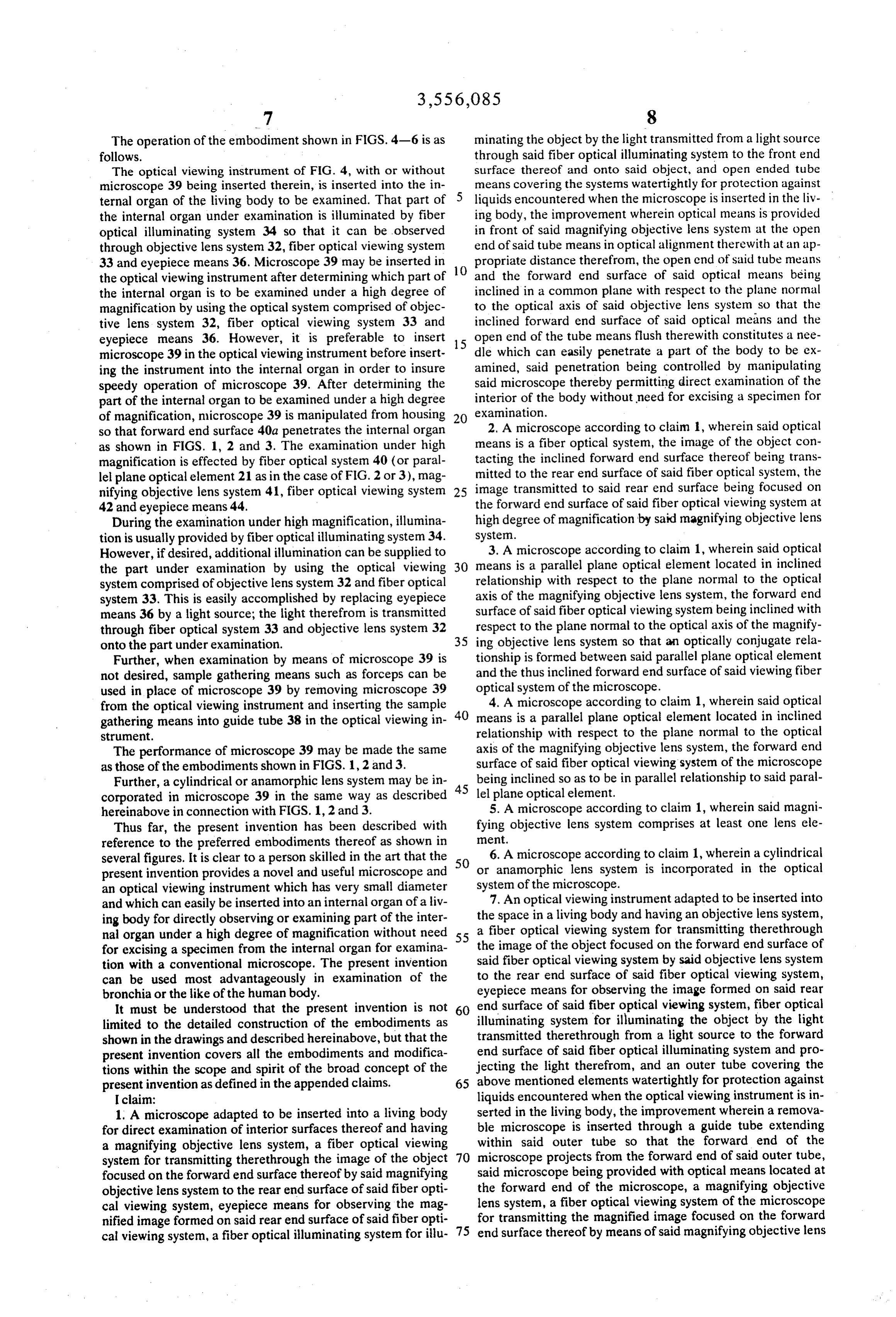
The operation of the embodiment shown in FIGS. 4-6 is as minating the object by the light transmitted from a light source follows. through said fiber optical illuminating system to the front end The optical viewing instrument of FIG. 4, with or without surface thereof and onto said object, and open ended tube microscope 39 being inserted therein, is inserted into the in means covering the systems watertightly for protection against ternal organ of the living body to be examined. That part of liquids encountered when the microscope is inserted in the liv the internal organ under examination is illuminated by fiber ing body, the improvement wherein optical means is provided optical illuminating system 34 so that it can be observed in front of said magnifying objective lens system at the open through objective lens system 32, fiber optical viewing system end of said tube means in optical alignment therewith at an ap 33 and eyepiece means 36. Microscope 39 may be inserted in 10 propriate distance therefrom, the open end of said tube means the optical viewing instrument after determining which part of and the forward end surface of said optical means being the internal organ is to be examined under a high degree of inclined in a common plane with respect to the plane normal magnification by using the optical system comprised of objec to the optical axis of said objective lens system so that the tive lens system 32, fiber optical viewing system 33 and inclined forward end surface of said optical means and the eyepiece means 36. However, it is preferable to insert 15 open end of the tube means flush therewith constitutes a nee microscope 39 in the optical viewing instrument before insert dle which can easily penetrate a part of the body to be ex ing the instrument into the internal organ in order to insure amined, said penetration being controlled by manipulating speedy operation of microscope 39. After determining the said microscope thereby permitting direct examination of the part of the internal organ to be examined under a high degree interior of the body without need for excising a specimen for of magnification, microscope 39 is manipulated from housing 20 examination.
so that forward end surface 4.0a penetrates the internal organ 2. A microscope according to claim 1, wherein said optical as shown in FIGS. 1, 2 and 3. The examination under high means is a fiber optical system, the image of the object con magnification is effected by fiber optical system 40 (or paral tacting the inclined forward end surface thereof being trans lel plane optical element 21 as in the case of FIG. 2 or 3), mag mitted to the rear end surface of said fiber optical system, the nifying objective lens system 41, fiber optical viewing system 25 image transmitted to said rear end surface being focused on 42 and eyepiece means 44. the forward end surface of said fiber optical viewing system at During the examination under high magnification, illumina high degree of magnification by said magnifying objective lens tion is usually provided by fiber optical illuminating system 34. system.
However, if desired, additional illumination can be supplied to 3. A microscope according to claim 1, wherein said optical the part under examination by using the optical viewing 30 means is a parallel plane optical element located in inclined system comprised of objective lens system 32 and fiber optical relationship with respect to the plane normal to the optical system 33. This is easily accomplished by replacing eyepiece axis of the magnifying objective lens system, the forward end means 36 by a light source; the light therefrom is transmitted surface of said fiber optical viewing system being inclined with through fiber optical system 33 and objective lens system 32 respect to the plane normal to the optical axis of the magnify onto the part under examination. 35 ing objective lens system so that an optically conjugate rela Further, when examination by means of microscope 39 is tionship is formed between said parallel plane optical element not desired, sample gathering means such as forceps can be and the thus inclined forward end surface of said viewing fiber used in place of microscope 39 by removing microscope 39 optical system of the microscope.
from the optical viewing instrument and inserting the sample 40 4. A microscope according to claim 1, wherein said optical gathering means into guide tube 38 in the optical viewing in means is a parallel plane optical element located in inclined Strument. relationship with respect to the plane normal to the optical The performance of microscope 39 may be made the same axis of the magnifying objective lens system, the forward end as those of the embodiments shown in FIGS. 1, 2 and 3. surface of said fiber optical viewing system of the microscope Further, a cylindrical or anamorphic lens system may be in 45 being inclined so as to be in parallel relationship to said paral corporated in microscope 39 in the same way as described lel plane optical element.
hereinabove in connection with FIGS. 1, 2 and 3. 5. A microscope according to claim 1, wherein said magni Thus far, the present invention has been described with fying objective lens system comprises at least one lens ele reference to the preferred embodiments thereof as shown in ment.
several figures. It is clear to a person skilled in the art that the 50 6. A microscope according to claim 1, wherein a cylindrical present invention provides a novel and useful microscope and or anamorphic lens system is incorporated in the optical an optical viewing instrument which has very small diameter system of the microscope.
and which can easily be inserted into an internal organ of a liv 7. An optical viewing instrument adapted to be inserted into ing body for directly observing or examining part of the inter the space in a living body and having an objective lens system, nal organ under a high degree of magnification without need 55 a fiber optical viewing system for transmitting therethrough for excising a specimen from the internal organ for examina said the image of the object focused on the forward end surface of tion with a conventional microscope. The present invention fiber optical viewing system by said objective lens system can be used most advantageously in examination of the to the rear end surface of said fiber optical viewing system, bronchia or the like of the human body. eyepiece means for observing the image formed on said rear It must be understood that the present invention is not 60 end surface of said fiber optical viewing system, fiber optical illuminating system for illuminating the object by the light limited to the detailed construction of the embodiments as transmitted therethrough from a light source to the forward shown in the drawings and described hereinabove, but that the present invention covers all the embodiments and modifica end surface of said fiber optical illuminating system and pro tions within the scope and spirit of the broad concept of the jecting the light therefrom, and an outer tube covering the present invention as defined in the appended claims. 65 above mentioned elements watertightly for protection against I claim: liquids encountered when the optical viewing instrument is in 1. A microscope adapted to be inserted into a living body serted in the living body, the improvement wherein a remova for direct examination of interior surfaces thereof and having ble microscope is inserted through a guide tube extending a magnifying objective lens system, a fiber optical viewing within said outer tube so that the forward end of the system for transmitting therethrough the image of the object 70 microscope projects from the forward end of said outer tube, focused on the forward end surface thereof by said magnifying said microscope being provided with optical means located at objective lens system to the rear end surface of said fiber opti the forward end of the microscope, a magnifying objective cal viewing system, eyepiece means for observing the mag lens system, a fiber optical viewing system of the microscope nified image formed on said rear end surface of said fiber opti for transmitting the magnified image focused on the forward cal viewing system, a fiber optical illuminating system for illu 75 end surface thereof by means of said magnifying objective lens
Page 8
system through said fiber optical viewing system of the respect to the plane normal to the optical axis of the magnify microscope to the rear end surface thereof, eyepiece means of ing objective lens system so that an optically conjugate rela the microscope for observing the magnified image on said rear tionship is given between said parallel plane optical element end surface of said fiber optical viewing system of the and the thus inclined forward end surface of said fiber optical microscope, the forward end surface of said optical means viewing system of the microscope. .
being inclined with respect to the plane normal to the optical 10. An optical viewing instrument according to claim 7, axis of said magnifying objective lens system so that said opti wherein said optical means in the microscope is a parallel cal means can easily penetrate that part of the body into which plane optical element located in inclined relationship with said optical viewing instrument is to be inserted, the image of respect to the plane normal to the optical axis of the magnify the object contacting the inclined forward end surface of said O ing objective lens system, the forward end surface of said fiber optical means being focused onto the forward end surface of optical viewing system of the microscope being inclined so as said fiber optical viewing system by means of said magnifying to be in parallel relationship to said parallel plane optical ele objective lens system, the positioning any penetration of said ent.
forward end surface being controlled by manipulating said 11. An optical viewing instrument according to claim 7, microscope while the object is being observed through the op 5 wherein means is provided in said outer tube for supplying tical system of the optical viewing instrument. dyeing or coloring agent to that part of the body to be ex 8. An optical viewing instrument according to claim 7, amined.
wherein said optical means in the microscope is a fiber optical 12. An optical viewing instrument according to claim 7 system, the image of the object contacting the inclined for wherein sample gathering means such as forceps can be used ward end surface of said fiber optical system being transmitted 20 in place of said microscope.
therethrough to the rear end surface thereof, the image thus 13. An optical viewing instrument according to claim 7, transmitted to said rear end surface of said fiber optical system wherein means is provided to connect the near end surface of being focused on the front end surface of said fiber optical viewing system of the microscope at high degree of magnifica the fiber optical viewing system of the viewing instrument to a tion. 25 light source in place of the eyepiece means thereby permitting 9. An optical viewing instrument according to claim 7; additional illumination to be given to the object through said wherein said optical means in the microscope is a parallel tion fiber optical viewing system of the viewing instrument in addi plane optical element located in inclined relationship with to the illumination by means of said fiber optical illu minating respect to the plane normal to the optical axis of the magnify of the object system when the microscope is used for examination ing objective lens system, the forward end surface of said fiber under a high degree of magnification. optical viewing system of the microscope being inclined with
Provenance
- Collection
- Cited prior art
- Original PDF
- patentimages.storage.googleapis.com →
- Filed
- 1968-02-26
- Pages
- 8
- Method
- pdftotext (the PDF's own text layer) + pdftoppm 300dpi page scans
- Source
- Google Patents bibliographic record
- Granted
- 1971-01-19
- Inventors
- Nagashige Takahashi; Olympus Optical Co Ltd
- Transcribed from
- patentimages.storage.googleapis.com →