patent · US3464330
Optical writing device
2 September 1969
Page 1
Drawing sheet — no readable text.
Page 2
Drawing sheet — no readable text.
Page 3
Drawing sheet — no readable text.
Page 4
Drawing sheet — no readable text.
Page 5
United States Patent Office arrationnaimanowan
Patented Sept. 2, 1969 site:
3,464,330 in combination with electroluminescent panels having sev OPTICAL WRITING DEVICE eral separately energizable segments, a multitude of spot Edward V. Lewis,
California Computer
Newport Beach,Inc.,Calif.,
Products, assignor
Anaheim, to sizes
Calif., and shapes can be achieved without making manual changes.
a corporation of California 5 The cartridge may be attached to standard plotting de
vices to record graphical information on photosensitive
U.S. C. 95-1 13 Claims recording medium. By synchronizing the light source with external commands, uniform exposures may be achieved irrespective of the motion of the cartridge relative to the
ABSTRACT OF THE DISCLOSURE, O recording medium.
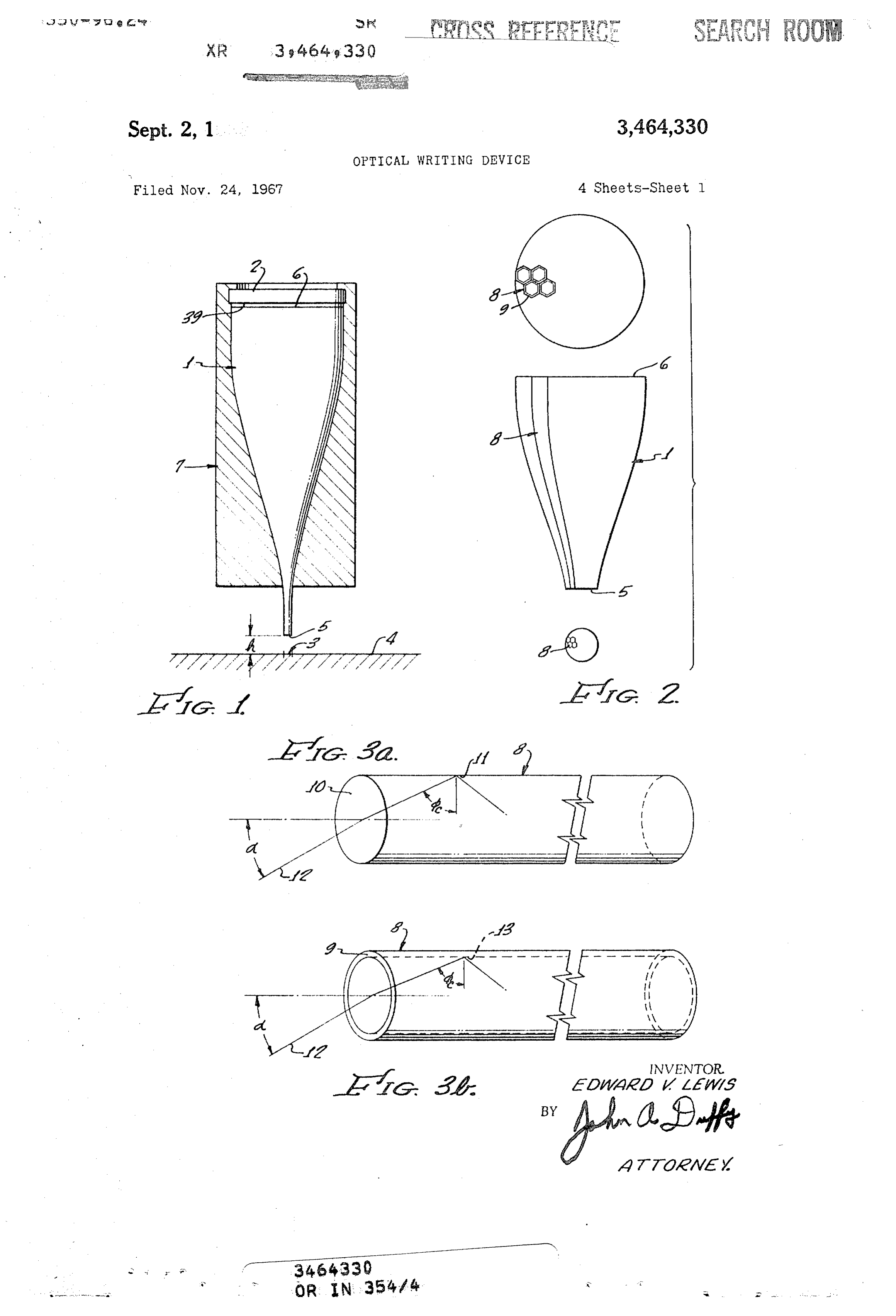
A tapered bundle of coated transparent fibers may be DESCRIPTION OF THE DRAWINGS utilized to collimate monochromatic light from a dis FIGURE 1 shows the structural relationship between tributed source into a narrow beam. The light source and the operative elements of a single station writing head. bundle may be mounted on a recording apparatus for FIGURE 2 shows the details of construction of a taper movement relative to a photosensitive medium in order ed fiber optic bundle.
to plot graphical information. By employing a plurality of FIGURE 3a shows the geometry of the reflective path bundles having different tapers in combination with light of a ray entering a single uncoated fiber at an angle equal Sources having separately energizable segments, a wide to the numerical aperture.
range able.
of line widths and intensities may be made avail FIGURE 3b shows the geometry for a ray entering a coated fiber,
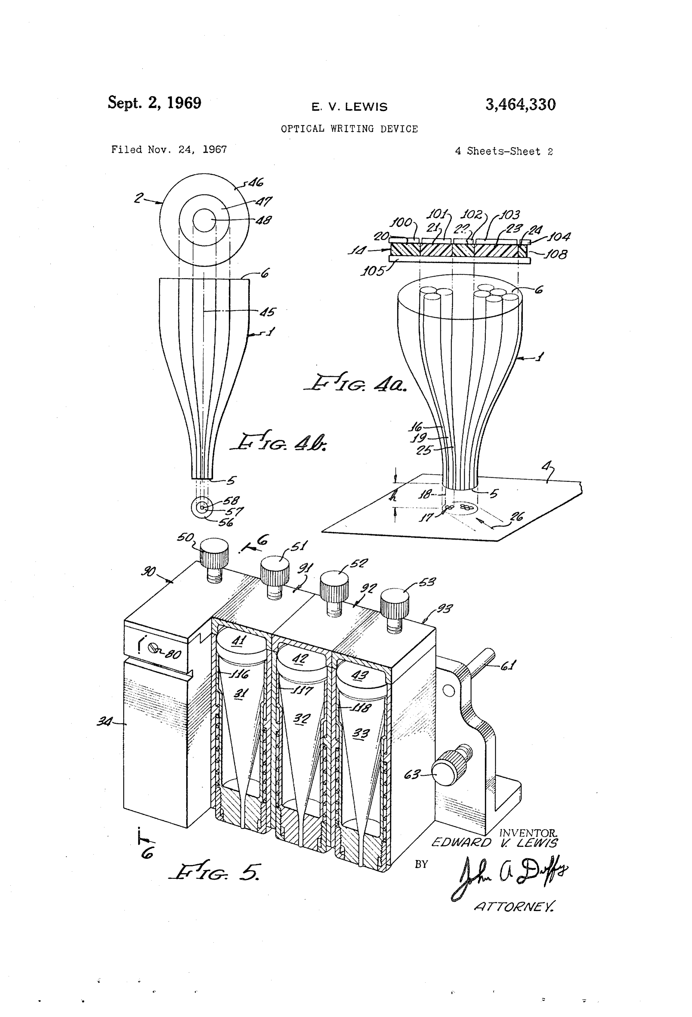
FIGURE 4a illustrates how beam characteristics may
BACKGROUND OF THE INVENTION be altered by energizing panels within the numerical aper ture of different fibers.
Information may be reduced to graphical form using 25 FIGURE 4b illustrates how the beam size may be al various drawing devices such as cathode ray tubes and tered without shifting its center.
drawing pen plotters. Where photographic regenerations FIGURE 5 illustrates an assembles for station car are required it is often desirable to lay out information tridge.
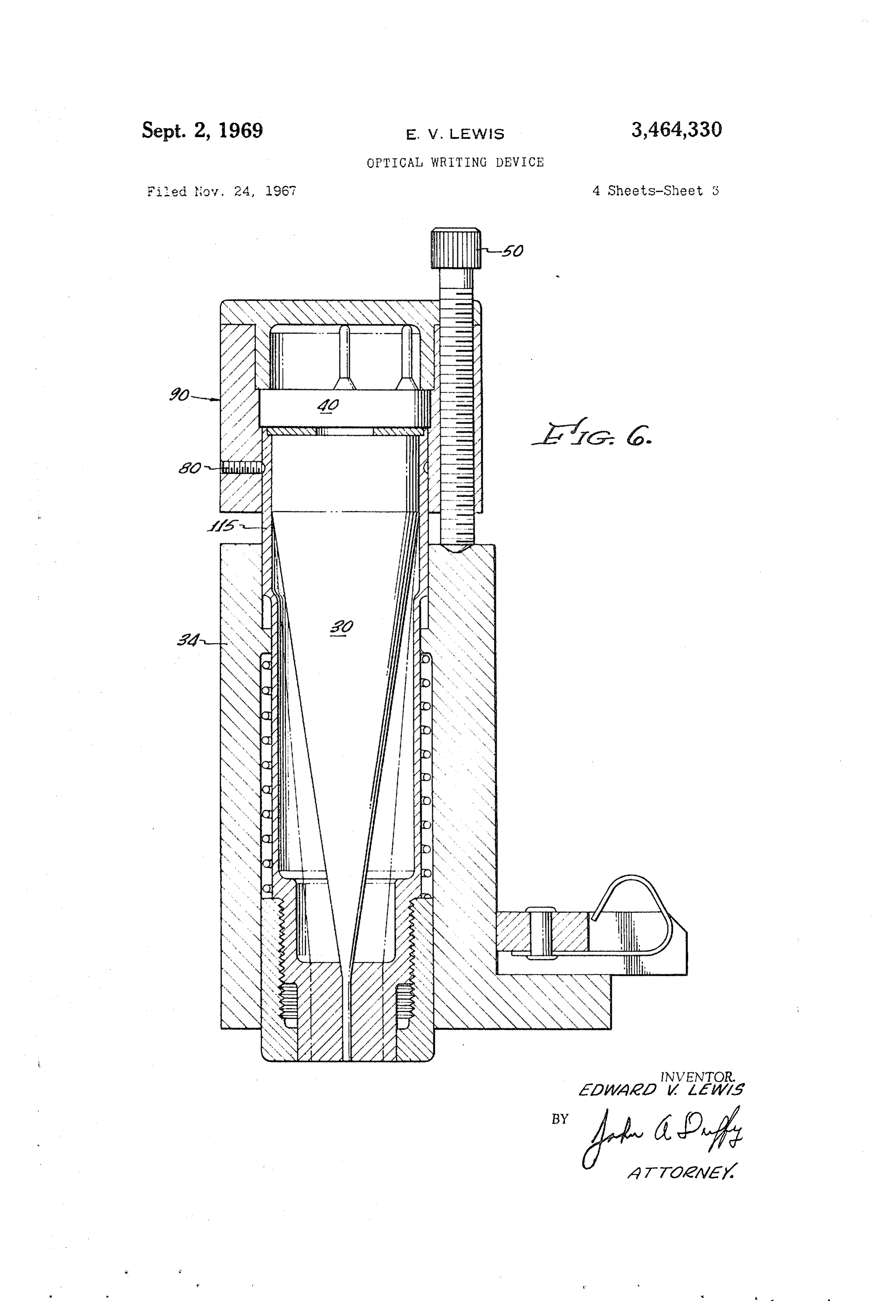
directly on photosensitive materials. Typical examples in FIGURE 6 is a cross sectional view illustrating the clude the manufacturing of printed circuit board masters, 30 fabrication details of a four station cartridge. integrated circuit board masters, and the art work for etched tooling and vacuum deposition tooling. Most of be attached to7 the
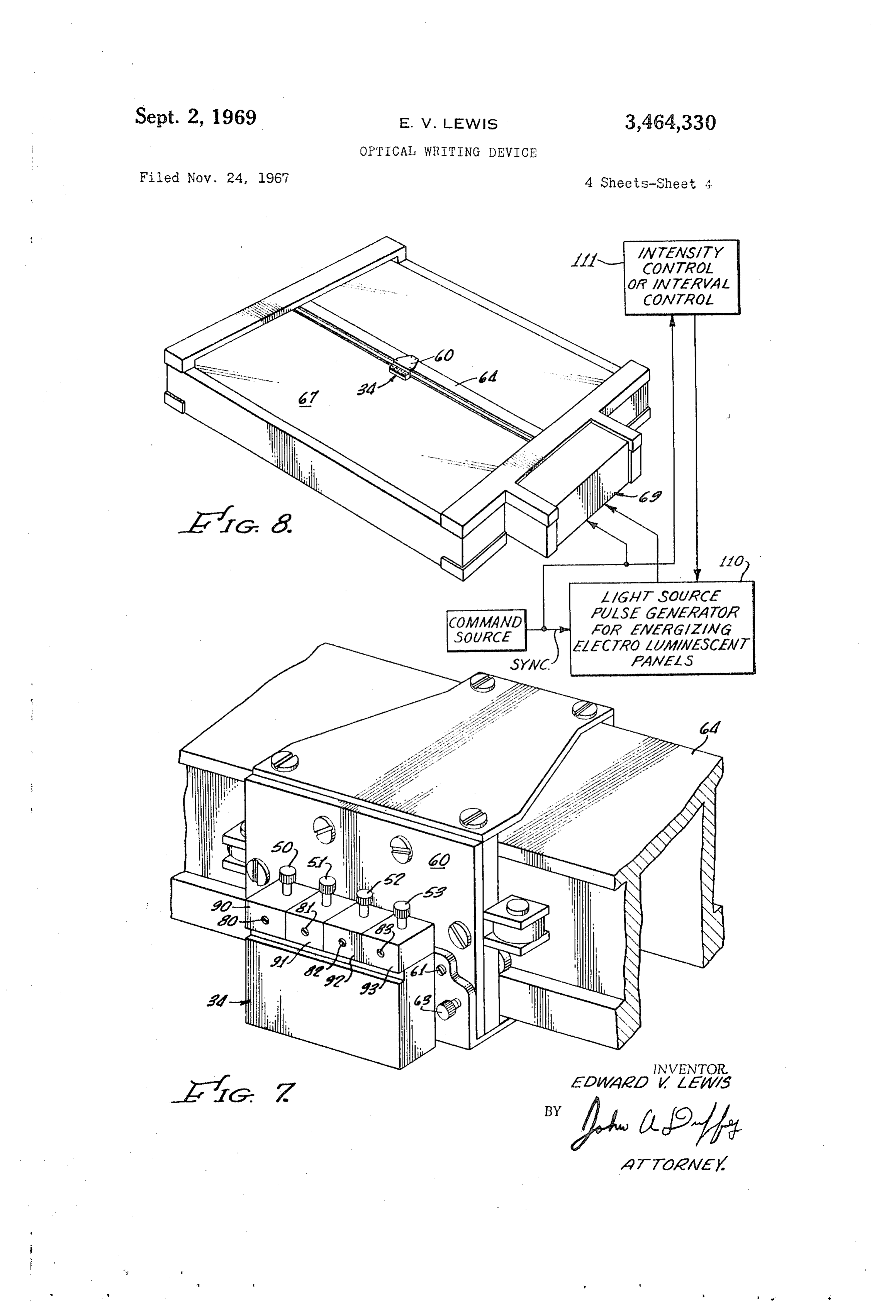
FIGURE shows how the four station cartridge may carriage of a graphical plotter.
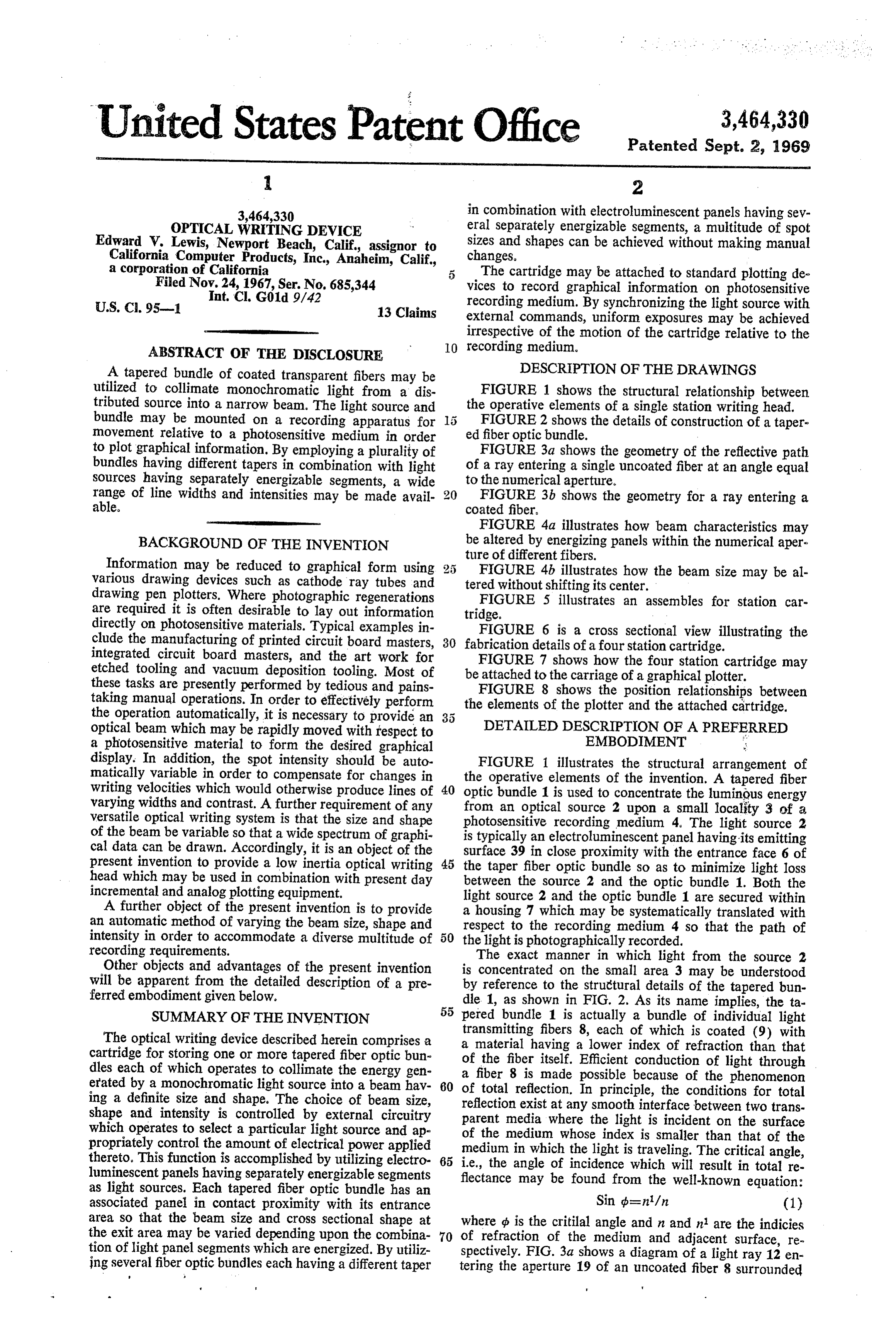
these tasks are presently performed by tedious and pains FIGURE 8 shows the position relationships between taking manual operations. In order to effectively perform the elements of the plotter and the attached cartridge. the operation automatically, it is necessary to provide an optical beam which may be rapidly moved with respect to DETAILED DESCRIPTION OF A PREFERRED a photosensitive material to form the desired graphical EMBODIMENT display. In addition, the spot intensity should be auto FIGURE 1 illustrates the structural arrangement of matically variable in order to compensate for changes in the operative elements of the invention. A tapered fiber writing velocities which would otherwise produce lines of 40 optic bundle 1 is used to concentrate the luminous energy varying widths and contrast. A further requirement of any from an optical source 2 upon a small locality 3 of a versatile optical writing system is that the size and shape photosensitive recording medium 4. The light source 2 of the beam be variable so that a wide spectrum of graphi is typically an electroluminescent panel having its emitting cal data can be drawn. Accordingly, it is an object of the surface 39 in close proximity with the entrance face 6 of present invention to provide a low inertia optical writing 45 the taper fiber optic bundle so as to minimize light loss head which may be used in combination with present day between the source 2 and the optic bundle 1. Both the incremental and analog plotting equipment.
A further object of the present invention is to provide a housing 7 2which light source and the optic bundle 1 are secured within may be systematically translated with an automatic method of varying the beam size, shape and respect to the recording medium 4 so that the path of intensity in order to accommodate a diverse multitude of 50 the light is photographically recorded. recording requirements. The exact manner in which light from the source 2 Other objects and advantages of the present invention will be apparent from the detailed description of a pre by concentrated
reference to on the small area 3 may be understood the structural details of the tapered bun ferred embodiment given below. dle 1, as shown in FIG. 2. As its name implies, the ta 55 pered bundle 1 is actually a bundle of individual light
SUMMARY OF THE INVENTION
The optical writing device described herein comprises a atransmitting fibers 8, each of which is coated (9) with cartridge for storing one or more tapered fiber optic bun ofmaterial having a lower index of refraction than that the fiber itself. Efficient conduction of light through dles each of which operates to collimate the energy gen a fiber erated by a monochromatic light source into a beam hav 60 of total 8reflection.
is made possible because of the phenomenon ing a definite size and shape. The choice of beam size, reflection exist at anyInsmooth principle, the conditions for total shape and intensity is controlled by external circuitry parent media where the lightinterface is between two trans incident on the surface which operates to select a particular light source and ap propriately control the amount of electrical power applied of the medium whose index is smaller than that of the medium in which the light is traveling. The critical angle, thereto. This function is accomplished by utilizing electro 65 i.e., the angle of incidence which will result in total re luminescent panels having separately energizable segments flectance may be found from the well-known equation: as light sources. Each tapered fiber optic bundle has an associated panel in contact proximity with its entrance Sin (p=n/n (1) area, so that the beam size and cross sectional shape at where p is the critilal angle and n and n are the indicies the exit area may be varied depending upon the combina 70 of refraction of the medium and adjacent surface, re tion of light panel segments which are energized. By utiliz spectively. FIG. 3a shows a diagram of a light ray 12 en ing several fiber optic bundles each having a different taper tering the aperture 19 of an uncoated fiber 8 surrounded
Page 6
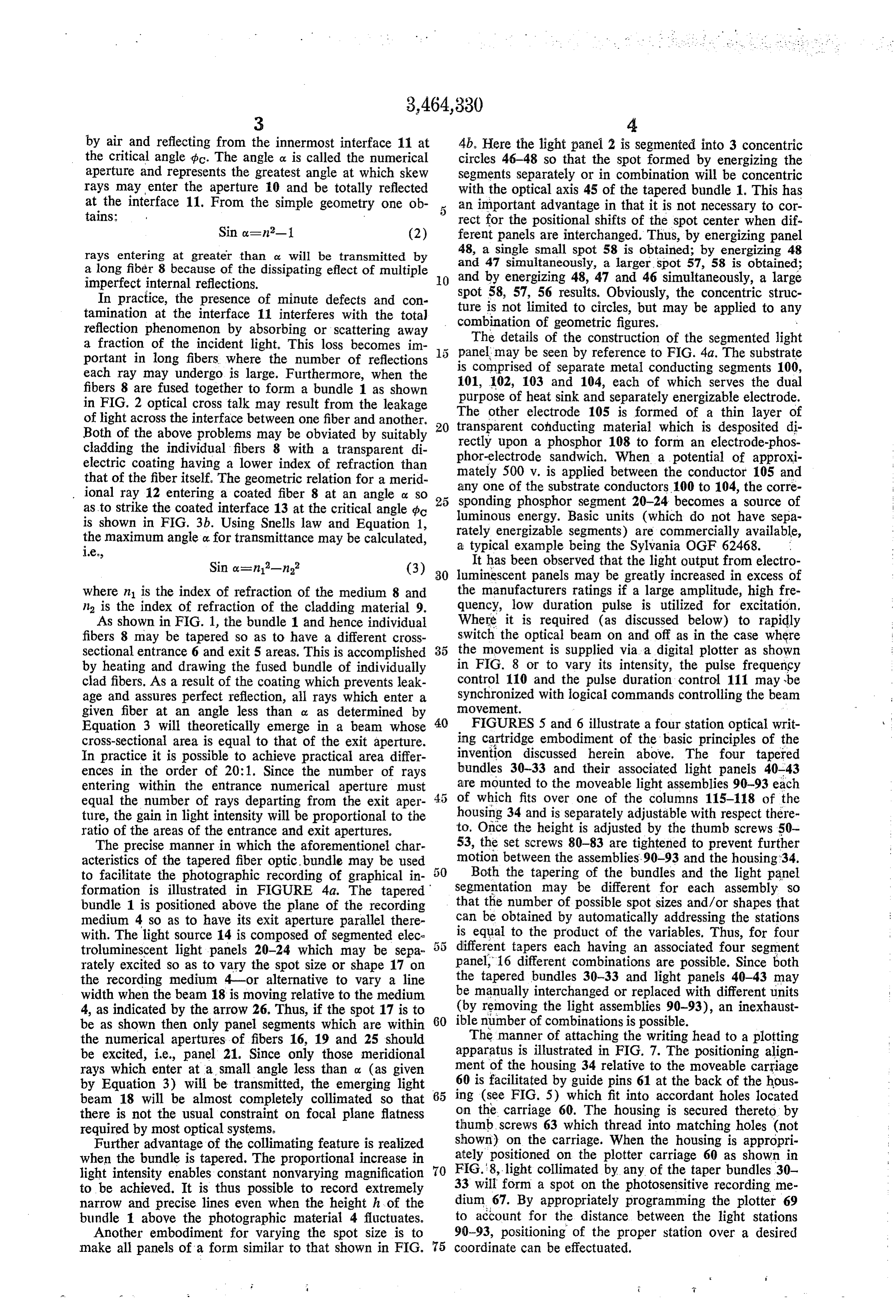
by air and reflecting from the innermost interface 11 at 4b. Here the light panel 2 is segmented into 3 concentric the critical angle pc. The angle a is called the numerical circles 46-48 so that the spot formed by energizing the aperture and represents the greatest angle at which skew segments separately or in combination will be concentric rays may enter the aperture 10 and be totally reflected with the optical axis 45 of the tapered bundle 1. This has at the interface 11. From the simple geometry one ob an important advantage in that it is not necessary to cor tains: rect for the positional shifts of the spot center when dif Sin ox=n-1 (2) ferent panels are interchanged. Thus, by energizing panel rays entering at greater than cz will be transmitted by 48, a single small spot 58 is obtained; by energizing 48 a long fiber 8 because of the dissipating effect of multiple and 47 simultaneously, a larger, spot 57, 58 is obtained; imperfect internal reflections. O and by energizing 48, 47 and 46 simultaneously, a large In practice, the presence of minute defects and con ture spot 58, 57, 56 results. Obviously, the concentric struc tamination at the interface 11 interferes with the total is not limited to circles, but may be applied to any reflection phenomenon by absorbing or scattering away combination The details of geometric figures.
of the construction of the segmented ligh a fraction of the incident light. This loss becomes im portant in long fibers where the number of reflections ispanel may be seen by reference to FIG.4a. The substrate comprised of separate metal conducting segments 100, each ray may undergo is large. Furthermore, when the fibers 8 are fused together to form a bundle 1 as shown 101, 102, 103 and 104, each of which serves the dual in FIG. 2 optical cross talk may result from the leakage purpose of heat sink and separately energizable electrode. of light across the interface between one fiber and another. 20 The other electrode 105 is formed of a thin layer of Both of the above problems may be obviated by suitably transparent cohducting material which is desposited di rectly upon a phosphor 108 to form an electrode-phos cladding the individual fibers 8 with a transparent di phor-electrode sandwich. When a potential of approxi electric coating having a lower index of refraction than mately 500 v. is applied between the conductor 105 and that of the fiber itself. The geometric relation for a merid ional ray 12 entering a coated fiber 8 at an angle ox so 25 any one of the substrate conductors 100 to 104, the corre sponding phosphor segment 20-24 becomes a source of as to strike the coated interface 13 at the critical angle po luminous energy. Basic units (which do not have sepa is shown in FIG. 3b. Using Snells law and Equation 1, rately energizable segments) are commercially available, the maximum angle o. for transmittance may be calculated, a typical example being the Sylvania OGF 62468.
Sin ox=nl-n It has been observed that the light output from electro (3) 30 luminescent panels may be greatly increased in excess of where n is the index of refraction of the medium 8 and the manufacturers ratings if a large amplitude, high fre n is the index of refraction of the cladding material 9. quency, low duration pulse is utilized for excitation, As shown in FIG. 1, the bundle 1 and hence individual Where it is required (as discussed below) to rapidly fibers 8 may be tapered so as to have a different cross switch the optical beam on and off as in the case where sectional entrance 6 and exit 5 areas. This is accomplished 35 the movement is supplied via a digital plotter as shown by heating and drawing the fused bundle of individually in FIG. 8 or to vary its intensity, the pulse frequency clad fibers. As a result of the coating which prevents leak control 110 and the pulse duration control 111 may be age and assures perfect reflection, all rays which enter a Insynchronized
Ovement.
with logical commands controlling the beam given fiber at an angle less than or as determined by
Equation 3 will theoretically emerge in a beam whose 40 FIGURES5 and 6 illustrate a four station optical writ cross-sectional area is equal to that of the exit aperture. ing cartridge embodiment of the basic principles of the In practice it is possible to achieve practical area differ invention discussed herein above. The four tapered ences in the order of 20:1. Since the number of rays bundles 30-33 and their associated light panels 40-43 entering within the entrance numerical aperture must are mounted to the moveable light assemblies 90-93 each equal the number of rays departing from the exit aper of which fits over one of the columns 115-118 of the ture, the gain in light intensity will be proportional to the housing 34 and is separately adjustable with respect there ratio of the areas of the entrance and exit apertures. to. Once the height is adjusted by the thumb screws 50 The precise manner in which the aforementionel char 53, the set screws 80-83 are tightened to prevent further acteristics of the tapered fiber optic. bundle may be used motion between the assemblies.90-93 and the housing 34. to facilitate the photographic recording of graphical in Both the tapering of the bundles and the light panel formation is illustrated in FIGURE 4a. The tapered segmentation may be different for each assembly so bundle 1 is positioned above the plane of the recording that the number of possible spot sizes and/or shapes that medium 4 so as to have its exit aperture parallel there can be obtained by automatically addressing the stations with. The light source 14 is composed of segmented elec 5 5 is equal to the product of the variables. Thus, for four troluminescent light panels 20-24 which may be sepa panel, different tapers each having an associated four segment rately excited so as to vary the spot size or shape 17 on the tapered16 different combinations are possible. Since both the recording medium 4-or alternative to vary a line be manually bundles 30-33 and light panels 40-43 may interchanged or replaced with different units width when the beam 18 is moving relative to the medium 4, as indicated by the arrow 26. Thus, if the spot 17 is to (by removing the light assemblies 90-93), an inexhaust be as shown then only panel segments which are within 60 ibleThe number of combinations is possible. manner of attaching the writing head to a plotting the numerical apertures of fibers 16, 19 and 25 should apparatus is illustrated in FIG. 7. The positioning align be excited, i.e., panel 21. Since only those meridional rays which enter at a small angle less than 0 (as given ment of the housing 34 relative to the moveable carriage by Equation 3) will be transmitted, the emerging light 65 60 is facilitated by guide pins 61 at the back of the hous beam 18 will be almost completely collimated so that ing (see FIG. 5) which fit into accordant holes located there is not the usual constraint on focal plane flatness on the carriage 60. The housing is secured thereto by required by most optical systems. thumb, screws 63 which thread into matching holes (not Further advantage of the collimating feature is realized shown) on the carriage. When the housing is appropri when the bundle is tapered. The proportional increase in ately positioned on the plotter carriage 60 as shown in FIG. 8, light collimated by any of the taper bundles 30 light intensity enables constant nonvarying magnification 70 33 to be achieved. It is thus possible to record extremely will form a spot on the photosensitive recording me narrow and precise lines even when the height h of the dium 67. By appropriately programming the plotter 69 bundle 1 above the photographic material 4 fluctuates. to account for the distance between the light stations Another embodiment for varying the spot size is to 90-93, positioning of the proper station over a desired make all panels of a form similar to that shown in FIG. 75 coordinate can be effectuated.
Page 7
When the present invention is utilized in combination 4. The combination comprising: an incremental plot with an existing plotting device 69 as shown in FIG. 8, it ting machine adapted to use photosensitive recording me is desirable to have available a means of regulating the dium; an optical writing cartridge having at least one star beam intensity so that uniform exposure is realized ir tion for recording on said photosensitive medium, and respective of the speed of travel of the light beam with 5 means for attaching said writing cartridge to said plotter, respect to the recording medium. Thus, assuming the said cartridge comprising a plurality of stations each hav beam 64 and carriage 60 of the plotter 69 are normally ing a source for generating optical energy; means for con moved in digital increments, it is necessary to Synchro centrating the energy generated by each source into a col nize the pulsing of the light beam with such incremental limated beam, each of said sources for generating optical movements in order to achieve uniform line widths. Fur energy comprising an electroluminescent light panel have thermore, if the beam and carriage are capable of simul 0 ing a plurality of separately energizable segments. taneous movement then the beam intensity must be in 5. The combination comprising: an incremental plot creased to account for the extra distance traveled per ting machine adapted to use photosensitive recording me increment. As previously explained of these functions can dium; an optical writing cartridge having at least one sta be accomplished by synchronizing the light panel excita tion for recording on said photosensitive medium; means tion with the electronic commands in the plotter so as to for attaching said writing cartridge to said plotter, said appropriately vary the luminous intensity. An important optical writing cartridge comprising a plurality of sta advantage of the electroluminescent light panel over other tions each having a source for generating optical energy; high intensity sources of monochromatic light is that they and a fiber optic bundle for concentrating the energy gen may be rapidly switched to achieve this result. The inten sity may also be made manually or automatically adjust 20 erated beam.
by each of said optical sources into a collimated
able in order to account for different recording medium 6. An apparatus for photographically recording graphi sensitivities.
The light source pulse generation 110 is typically a cal information comprising: a bed for holding a photo sensitive recording medium; a cartridge having a source one-shot multivibrator, which may be triggered by the for generating at least one beam of optical energy; means command source to generate a coincident voltage pulse 25 for moving said cartridge relative to said photosensitive for energizing an electroluminescent panel. The intensity medium whereby the motion of said optical energy beam control. 111 may employ a frequency to voltage converter may be graphically recorded; said cartridge comprising: for producing an excitation potential which is propor a housing having a hole extended therethrough to form a tional to the step command rate. Thus, when the com cylindrical column; a light assembly having an aperture mand rate is high, the amplitude of the excitation voltage 30 adapted to fit over said cylindrical column whereby said will be proportionally increased in order to maintain a light assembly may be moved in sliding contact with said uniform line width independent of plotting speed. The cylindrical column; and electroluminescent light panel design details of both the light source pulse generator 110 having at least one separately energizable segment, said and the intensity control 111 have been omitted as they panel to be attached to said light assembly and moveable form no part of the present invention.
The present invention may be utilized in conjunction therewith, said light panel to be oriented to have its op tical axis parallel with said cylinder column; a tapered with either analog or incremental plotters having flat, fiber optic bundle attached to said light assembly and drum or other bed configurations; it may be utilized in moveable therewith, said bundle to be positioned to have facsimile reproduction devices or in combination with 40 its entrance aperture adjacent to said panel, and aligned general purpose recorders and oscillographs. The optical to collimate the energy from said panel in a beam p?rallel intensity may be modulated to record audio or video in with said cylindrical column whereby said bundle may be formation. Other applications include generating masters for printing plates and accurate scale drafting and gen moved within said cylinder hole as said light assembly is moved so as to vary the distance between the exit apera eral use in combination with any apparatus utilized to 45 ture of said bundle and said photosensitive mediurn. draft drawings, charts and layouts. 7. An apparatus for photographically recording graphi Although a four station device has been illustrated in cal information comprising: a bed for holding a photo combination with an incremental plotter, it will be under sensitive recording medium; a cartridge having a source stood that the basic concept is equally applicable to al for generating at least one beam of optical energy; means ternative embodiments having a greater or lesser number 50 for moving said cartridge relative to said photosensitive of stations, and that the principles of the invention are not medium whereby the motion of said optical energy beam limited in application to utilization in combination with may be graphically recorded, said cartridge comprising: a specific apparatus, such description being made only by a housing having a plurality of parallel columns, each of way of example and not as a limitation on the scope of said columns having a cylindrical hole concentric there the invention. 55 with and extending through said housing; a plurality of I claim:
1. In a graphical recording system having a photosen light assemblies each having an aperture adapted to fit over said cylindrical columns whereby said light assem sitive recording medium, a recording head comprising: blies may be moved in sliding contact therewith; an elec at least one electroluminescent panel having a plurality troluminescent light panel having at least one separately of separately energizable segments; means for collimating energizable segment attached to each of said light assem said optical energy in a narrow beam; means for separate 60 blies and moveable therewith, each of said light panels ly energizing said electroluminescent panels whereby the to be oriented to have its optical axis parallel with said cross sectional characteristics of said beam may be varied. cylinder columns; a tapered fiber optic bundle attached to 2. The apparatus recited in claim 1 wherein said means each of said light assemblies and moveable therewith, for collimating said optical energy in a narrow beam com 65 each of said bundles to be positioned to have their en prises at least one tapered fiber optic bundle. trance apertures adjacent to one of said panels and 3. In combination with a graphical recorder adapted aligned to collimate the energy from said panel in a to use photosensitive recording medium, an optical writ beam parallel with said cylindrical columns whereby each ing cartridge comprising a housing having at least one of said bundles may be moved within their associated cyl station for writing, each of said writing stations compris inder holes as said associated light assembly is moved, so ing: a segmented electroluminescent panel for generating as to vary the distance between the exit apertures of said optical energy; a tapered fiber optic bundle adjacent to bundles and said photosensitive medium. said panel for collimating the optical energy emitted by 8. An apparatus for recording graphical information said segmented electroluminescent panel into a narrow on photosensitive recording medium comprising: a cart beam. 75 ridge having a plurality of sources for generating optical
Page 8
beams of different sizes and shapes; means for moving through to form a cylindrical column; a light assembly said cartridge relative to said photosensitive medium for having an aperature adapted to fit over said cylindrical recording thereon; means for varying said optical beams column whereby said light assembly may be moved in to accommodate for the speed of movement of said beam sliding contact with said cylindrical column; said plurality relative to said photosensitive medium; said cartridge of sources comprising an electroluminescent light panel comprising: a housing having a plurality of parallel col having a plurality of separately energizable segments, said umns, each of said colums having a cylindrical hole con panel to be attached to said light assembly and moveable centric therewith and extending through said housing: therewith, said light panel to be oriented to have its optical a plurality of light assemblies each having an aperture axis parallel with said cylinder column; a tapered fiber adapted to fit over said cylindrical columns whereby said O optic bundle attached to said light assembly and move light assemblies may be moved in sliding contact there able therewith, said bundle to be positioned to have its with; each of said plurality of sources comprising: an entrance aperture adjacent to said panel, and aligned to electroluminescent light panel having at least one sep collimate the energy from said panel in a beam parallel arately energizable segment attached to each of said with said cylindrical column whereby said bundle may light assemblies and moveable therewith, each of said be moved within said cylinder hole as said light assembly light panels to be oriented to have its optical axis parallel is moved so as to vary the distance between the exit with said cylinder columns; a tapered fiber optic bundle aperture of said bundle and said photosensitive medium. attached to each of said light assemblies and moveable 12. The apparatus claimed in claim 11 wherein said therewith, each of said bundles to be positioned to have means for moving said cartridge comprises an incre their entrance apertures adjacent to one of Said panels 20 mental recorder.
and aligned to collimate the energy from said panel in a 13. The apparatus claimed in claim 12 wherein said beam parallel with said cylindrical columns whereby means for varying said optical beams comprises: a pulse each of said bundles may be moved within their associated generator responsively coupled to external plotter com cylinder holes as said associated light assembly is moved, mands to synchronize and control the durations of energy so as to vary the distance between the exit apertures of 25 applied to said panels whereby the exposure of said photo said bundles and said photosensitive medium. sensitive medium is not dependent upon step magnitude 9. The apparatus claimed in claim 8 wherein said and frequency.
means for moving said cartridge comprises an incremental References Cited recorder, UNITED STATES PATENTS 10. The apparatus claimed in claim 9 wherein said 30 1,597,487 8/1926 St. Clair ------------ 346-108 means for varying said optical beams comprises: a pulse 2,368,839 2/1945 Jansen --------------- 95-1.1 generator responsively coupled to external plotter com 2,992,587 7/1961 Hicks et al. --------- 350-96 mands to synchronize and control the duration of energy 3,019,344 1/1962. Seidman et al. 250 213 X applied to said panels whereby the exposure of said photo 3,027,219 3/1962 Bradley ----------- 350-96 X sensitive medium is not dependent upon step magnitude and frequency. 3,235,672 2/1966 Beguin ---------- 250-227 X 11. An apparatus for recording graphical information 3,245,083 4/1966 Wilson et al. 346-109 on photosensitive recording medium comprising: a car 3,258,776 6/1966 Boyle et al. --------- 346-29 tridge having a plurality of sources for generating optical 3,303,374 2/1967 Fyler ------------- 350-96 X beams of different sizes and shapes; means for moving 40 3,330,182 7/1967 Gerber et al. -------- 95-1 said cartridge relative to said photosensitive medium for recording thereon; means for varying said optical beams JOSEPH. W. HARTARY, Primary Examiner to accommodate for the speed of movement of said beam relative to said photosensitive medium, said cartridge U.S. C. X.R. comprising: a housing having a hole extended there 4. 346-108, 29; 350-96
Provenance
- Collection
- Cited prior art
- Original PDF
- patentimages.storage.googleapis.com →
- Filed
- 1967-11-24
- Pages
- 8
- Method
- pdftotext (the PDF's own text layer) + pdftoppm 300dpi page scans
- Source
- Google Patents bibliographic record
- Granted
- 1969-09-02
- Inventors
- Edward V Lewis; California Computer Products Inc
- Transcribed from
- patentimages.storage.googleapis.com →